2009 INFINITI QX56 washer fluid
[x] Cancel search: washer fluidPage 3652 of 4171

TM-4
Precaution for Supplemental Restraint System
(SRS) "AIR BAG" and "SEAT BELT PRE-TEN-
SIONER" ................................................................
174
Precaution Necessary for Steering Wheel Rota-
tion After Battery Disconnect .................................
174
Precaution for On Board Diagnosis (OBD) System
of A/T and Engine ..................................................
175
Precaution .............................................................175
Service Notice or Precaution .................................176
PREPARATION ..........................................177
PREPARATION .............................................. .177
Special Service Tool ............................................ ..177
Commercial Service Tool ......................................178
ON-VEHICLE MAINTENANCE ..................179
A/T FLUID ....................................................... .179
Checking the A/T Fluid (ATF) .............................. ..179
Changing the A/T Fluid (ATF) ................................181
A/T FLUID COOLER ........................................183
A/T Fluid Cooler Cleaning ................................... ..183
Inspection ..............................................................185
STALL TEST ....................................................186
Inspection and Judgment .................................... ..186
LINE PRESSURE TEST ..................................188
Inspection and Judgment .................................... ..188
ROAD TEST .....................................................190
Description ........................................................... ..190
Check Before Engine Is Started ............................190
Check At Idle .........................................................190
Cruise Test - Part 1 ...............................................191
Cruise Test - Part 2 ...............................................193
Cruise Test - Part 3 ...............................................194
Vehicle Speed When Shifting Gears .....................194
Vehicle Speed When Performing and Releasing
Complete Lock-up .................................................
194
A/T POSITION .................................................195
Adjustment of A/T Position .................................. ..195
Checking of A/T Position .......................................195
ON-VEHICLE REPAIR ............................. ..196
SHIFT CONTROL SYSTEM ........................... .196
A/T Shift Selector Removal and Installation ........ ..196
AIR BREATHER HOSE ...................................197
2WD ........................................................................ ..197
2WD : Removal and Installation ............................197
4WD ........................................................................ ..197
4WD : Removal and Installation ............................197
OIL PAN ...........................................................201
Oil Pan ................................................................. .201
CONTROL VALVE WITH TCM ........................203
Control Valve with TCM and A/T Fluid Tempera-
ture Sensor 2 ....................................................... .
203
REAR OIL SEAL ..............................................212
Rear Oil Seal ........................................................ .212
FLUID COOLER SYSTEM ...............................213
Exploded View ..................................................... .213
Removal and Installation .......................................213
REMOVAL AND INSTALLATION .............214
TRANSMISSION ASSEMBLY ........................ ..214
Removal and Installation (2WD) .......................... .214
Removal and Installation (4WD) ...........................216
DISASSEMBLY AND ASSEMBLY ...........220
OVERHAUL .................................................... ..220
Component .......................................................... .220
Oil Channel ...........................................................227
Location of Adjusting Shims, Needle Bearings,
Thrust Washers and Snap Rings ......................... .
229
DISASSEMBLY .............................................. ..232
Disassembly ......................................................... .232
REPAIR FOR COMPONENT PARTS ..............249
Oil Pump .............................................................. .249
Front Sun Gear, 3rd One-Way Clutch ...................251
Front Carrier, Input Clutch, Rear Internal Gear .....253
Mid Sun Gear, Rear Sun Gear, High and Low Re-
verse Clutch Hub ..................................................
258
High and Low Reverse Clutch ..............................263
Direct Clutch .........................................................265
ASSEMBLY .................................................... ..268
Assembly (1) ........................................................ .268
Adjustment ............................................................281
Assembly (2) .........................................................283
SERVICE DATA AND SPECIFICATIONS
(SDS) ............... ..........................................
290
SERVICE DATA AND SPECIFICATIONS
(SDS) .............................................................. ..
290
General Specification ........................................... .290
Vehicle Speed at Which Gear Shifting Occurs .....290
Vehicle Speed at Which Lock-up Occurs/Releas-
es ..........................................................................
291
Stall Speed ............................................................291
Line Pressure ........................................................291
Input Speed Sensor ..............................................291
Output Speed Sensor ...........................................291
Reverse Brake ......................................................291
Total End Play .......................................................292
Torque Converter .................................................
Revision: December 20092009 QX56
Page 3824 of 4171
TM-176
< PRECAUTION >
PRECAUTIONS
All parts should be carefully cleaned with a general purpose, non-flammable solvent before inspection orreassembly.
Gaskets, seals and O-rings should be replaced any time the transmission is disassembled.
It is very important to perform functional tests whenever they are indicated.
The valve body contains precision parts and requires extreme care when parts are removed and serviced. Place disassembled valve body parts in order for easier and proper assembly. Care will also prevent springs
and small parts from becoming scattered or lost.
Properly installed valves, sleeves, plugs, etc. will s lide along bores in valve body under their own weight.
Before assembly, apply a coat of recommended ATF to all parts. Apply petroleum jelly to protect O-rings and
seals, or hold bearings and washers in place during assembly. Do not use grease.
Extreme care should be taken to avoid damage to O-rings, seals and gaskets when assembling.
Clean or replace ATF cooler if excessive foreign material is found in oil pan or clogging strainer. Refer to TM-
183, "A/T Fluid Cooler Cleaning".
After overhaul, refill the transmission with new ATF.
When the A/T drain plug is removed, only some of the fluid is drained. Old A/T fluid will remain in torque con- verter and ATF cooling system.
Always follow the procedures under “Changing A/T Fluid” in the AT section when changing A/T fluid. Refer to
TM-181, "Changing the A/T Fluid (ATF)"
.
Service Notice or PrecautionINFOID:0000000003772016
ATF COOLER SERVICE
If A/T fluid contains fictional material (clutches, bands, etc.), or if an A/T is repaired, overhauled, or replaced,
inspect and clean the A/T fluid cooler mounted in the radiat or or replace the radiator. Flush cooler lines with
cleaning solvent and compressed air after repair. For A/T fluid cooler cleaning procedure, refer to TM-183,
"A/T Fluid Cooler Cleaning". For radiator replacement, refer to CO-15, "Removal and Installation".
CHECKING AND CHANGING A/T FLUID
Increase ATF oil temperature to 80 °C (176 °F) first, then check and adjust oil level at 65 °C (149 °F).
NOTE:
The A/T has both water cooling and air cooling systems . The air cooling system has a bypass valve. When
ATF oil temperature is at or below 50 °C (122 °F), it does not flow through the air cooled system. If A/T oil
level is adjusted without flow throughout the entir e system, the level will be 10mm lower than required.
Therefore, all piping should be filled with oil when adjusting level.
OBD-II SELF-DIAGNOSIS
A/T self-diagnosis is performed by the TCM in combination with the ECM. Refer to the table on TM-32,
"CONSULT-III Function (TRANSMISSION)" for the indicator used to display each self-diagnostic result.
The self-diagnostic results indicated by the MIL ar e automatically stored in both the ECM and TCM memo-
ries.
Always perform the procedure on TM-30, "OBD-II Diagnostic Trouble Code (DTC)"
to complete the
repair and avoid unnecessary blinking of the MIL.
For details of OBD-II, refer to TM-30
.
Certain systems and components, especially those related to OBD, may use the new style slide-
locking type harness connector. For descrip tion and how to disconnect, refer to PG-68
.
Revision: December 20092009 QX56
Page 3862 of 4171
TM-214
< REMOVAL AND INSTALLATION >
TRANSMISSION ASSEMBLY
REMOVAL AND INSTALLATION
TRANSMISSION ASSEMBLY
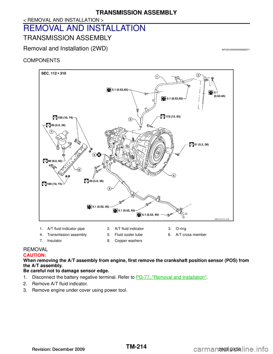
Removal and Installation (2WD)INFOID:0000000005892371
COMPONENTS
REMOVAL
CAUTION:
When removing the A/T assembly from engine, first remove the crankshaft position sensor (POS) from
the A/T assembly.
Be careful not to damage sensor edge.
1. Disconnect the battery negative terminal. Refer to PG-77, "Removal and Installation"
.
2. Remove A/T fluid indicator.
3. Remove engine under cover using power tool.
1. A/T fluid indicator pipe 2. A/T fluid indicator 3. O-ring
4. Transmission assembly 5. Fluid cooler tube 6. A/T cross member
7. Insulator 8. Copper washers
AWDIA0553GB
Revision: December 20092009 QX56
Page 3865 of 4171
TRANSMISSION ASSEMBLYTM-217
< REMOVAL AND INSTALLATION >
CEF
G H
I
J
K L
M A
B
TM
N
O P
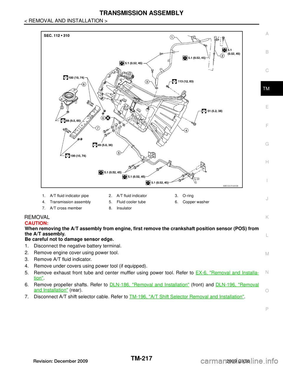
REMOVAL
CAUTION:
When removing the A/T assembly from engine, firs t remove the crankshaft position sensor (POS) from
the A/T assembly.
Be careful not to damage sensor edge.
1. Disconnect the negative battery terminal.
2. Remove engine cover using power tool.
3. Remove A/T fluid indicator.
4. Remove under covers using power tool (if equipped).
5. Remove exhaust front tube and center muffler using power tool. Refer to EX-6, "Removal and Installa-
tion".
6. Remove propeller shafts. Refer to DLN-186, "Removal and Installation"
(front) and DLN-196, "Removal
and Installation" (rear).
7. Disconnect A/T shift selector cable. Refer to TM-196, "A/T Shift Selector Removal and Installation"
.
1. A/T fluid indicator pipe 2. A/T fluid indicator 3. O-ring
4. Transmission assembly 5. Fluid cooler tube 6. Copper washer
7. A/T cross member 8. Insulator
AWDIA0548GB
Revision: December 20092009 QX56
Page 4005 of 4171
WCS-28
< ECU DIAGNOSIS >
COMBINATION METER
ECU DIAGNOSIS
COMBINATION METER
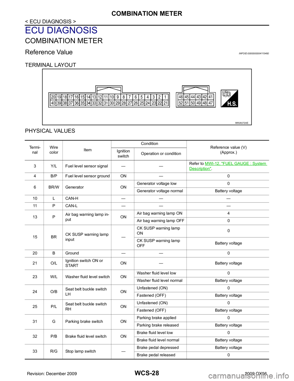
Reference ValueINFOID:0000000004115460
TERMINAL LAYOUT
PHYSICAL VALUES
WKIA5724E
Te r m i -nal Wire
color Item Condition
Reference value (V)
(Approx.)
Ignition
switch Operation or condition
3 Y/L Fuel level sensor signal — —Refer to MWI-12, "
FUEL GAUGE : System
Description".
4 B/P Fuel level sensor ground ON —0
6 BR/W Generator ONGenerator voltage low
0
Generator voltage normal Battery voltage
10 L CAN-H —— —
11 P C A N - L —— —
13 P Air bag warning lamp in-
put ONAir bag warning lamp ON
4
Air bag warning lamp OFF 0
15 BR CK SUSP warning lamp
input —CK SUSP warning lamp
ON
0
CK SUSP warning lamp
OFF Battery voltage
20 B Ground —— 0
21 O/L Ignition switch ON or
START ON
— Battery voltage
23 W/L Washer fluid level switch ON Washer fluid level low
0
Washer fluid level normal Battery voltage
24 O/B Seat belt buckle switch
LH ONUnfastened (ON)
0
Fastened (OFF) Battery voltage
25 P/L Seat belt buckle switch
RH ONUnfastened (ON)
0
Fastened (OFF) Battery voltage
31 G Parking brake switch ON Parking brake applied
0
Parking brake released Battery voltage
32 P/B Brake fluid level switch ON Brake fluid level low
0
Brake fluid level normal Battery voltage
33 R/G Stop lamp switch —Brake pedal depressed
Battery voltage
Brake pedal released 0
Revision: December 20092009 QX56
Page 4089 of 4171

WW-2
Wiring Diagram .......................................................61
Fail Safe .................................................................64
SYMPTOM DIAGNOSIS .............................66
WIPER AND WASHER SYSTEM SYMPTOMS
...
66
Symptom Table ................................................... ...66
NORMAL OPERATING CONDITION ................69
Description ........................................................... ...69
FRONT WIPER DOES NOT OPERATE ............70
Description ........................................................... ...70
Diagnosis Procedure ..............................................70
PRECAUTION .............................................72
PRECAUTION ... .............................................. ...72
Precaution for Supplemental Restraint System
(SRS) "AIR BAG" and "SEAT BELT PRE-TEN-
SIONER" .............................................................. ...
72
Precaution Necessary for Steering Wheel Rota-
tion After Battery Disconnect ..................................
72
ON-VEHICLE REPAIR ................................74
FRONT WIPER ARM ...................................... ...74
Front Wiper Arms ................................................ ...74
FRONT WIPER DRIVE ASSEMBLY .................75
Wiper Motor and Linkage ..................................... ...75
FRONT WASHER TUBE ...................................76
Washer Tube Layout ............................................ ...76
FRONT WASHER NOZZLE ..............................77
Washer Nozzle Adjustment .................................. ...77
WASHER TANK ................................................78
Washer Fluid Reservoir ..........................................78
FRONT WASHER PUMP ..................................79
Washer Motor ...................................................... ...79
FRONT WIPER AND WASHER SWITCH .........80
Wiper and Washer Switch .................................... ...80
REAR WIPER AND WASHER SYSTEM ...........81
Rear Wiper Arm ................................................... ...81
Rear Wiper Motor ....................................................81
Rear Washer Nozzle Adjustment ............................82
Rear Washer Tube Layout ......................................83
Rear Washer Nozzle ...............................................83
Rear Wiper and Washer Switch ..............................83
Washer Fluid Reservoir ....................................... ...84
Washer Motor .........................................................84
Revision: December 20092009 QX56
Page 4094 of 4171
FRONT WIPER AND WASHER SYSTEMWW-7
< FUNCTION DIAGNOSIS >
C
DE
F
G H
I
J
K
M A
B
WW
N
O P
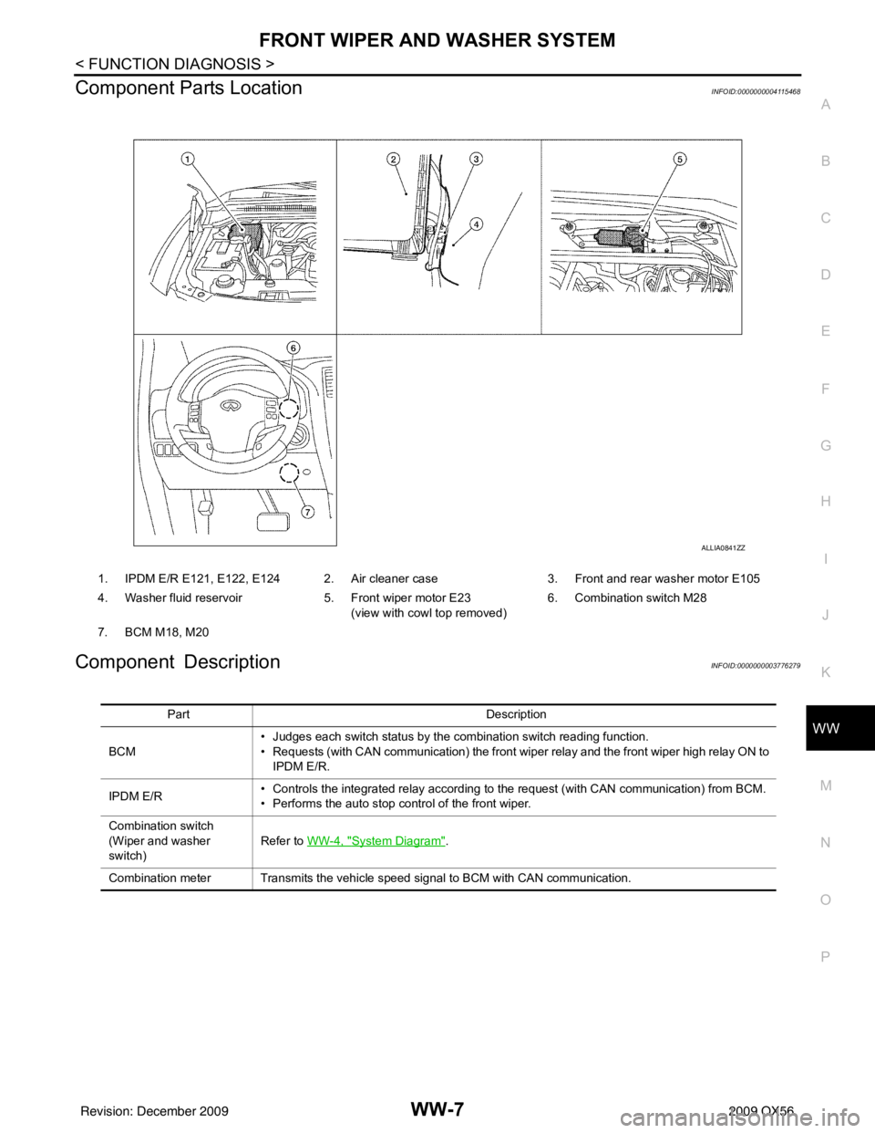
Component Parts LocationINFOID:0000000004115468
Component DescriptionINFOID:0000000003776279
1. IPDM E/R E121, E122, E124 2. Air cleaner case 3. Front and rear washer motor E105
4. Washer fluid reservoir 5. Front wiper motor E23
(view with cowl top removed) 6. Combination switch M28
7. BCM M18, M20
ALLIA0841ZZ
Part Description
BCM • Judges each switch status by the combination switch reading function.
• Requests (with CAN communication) the front wiper relay and the front wiper high relay ON to
IPDM E/R.
IPDM E/R • Controls the integrated relay according to the request (with CAN communication) from BCM.
• Performs the auto stop control of the front wiper.
Combination switch
(Wiper and washer
switch) Refer to WW-4, "
System Diagram".
Combination meter Transmits the vehicle speed signal to BCM with CAN communication.
Revision: December 20092009 QX56
Page 4097 of 4171
WW-10
< FUNCTION DIAGNOSIS >
REAR WIPER AND WASHER SYSTEM
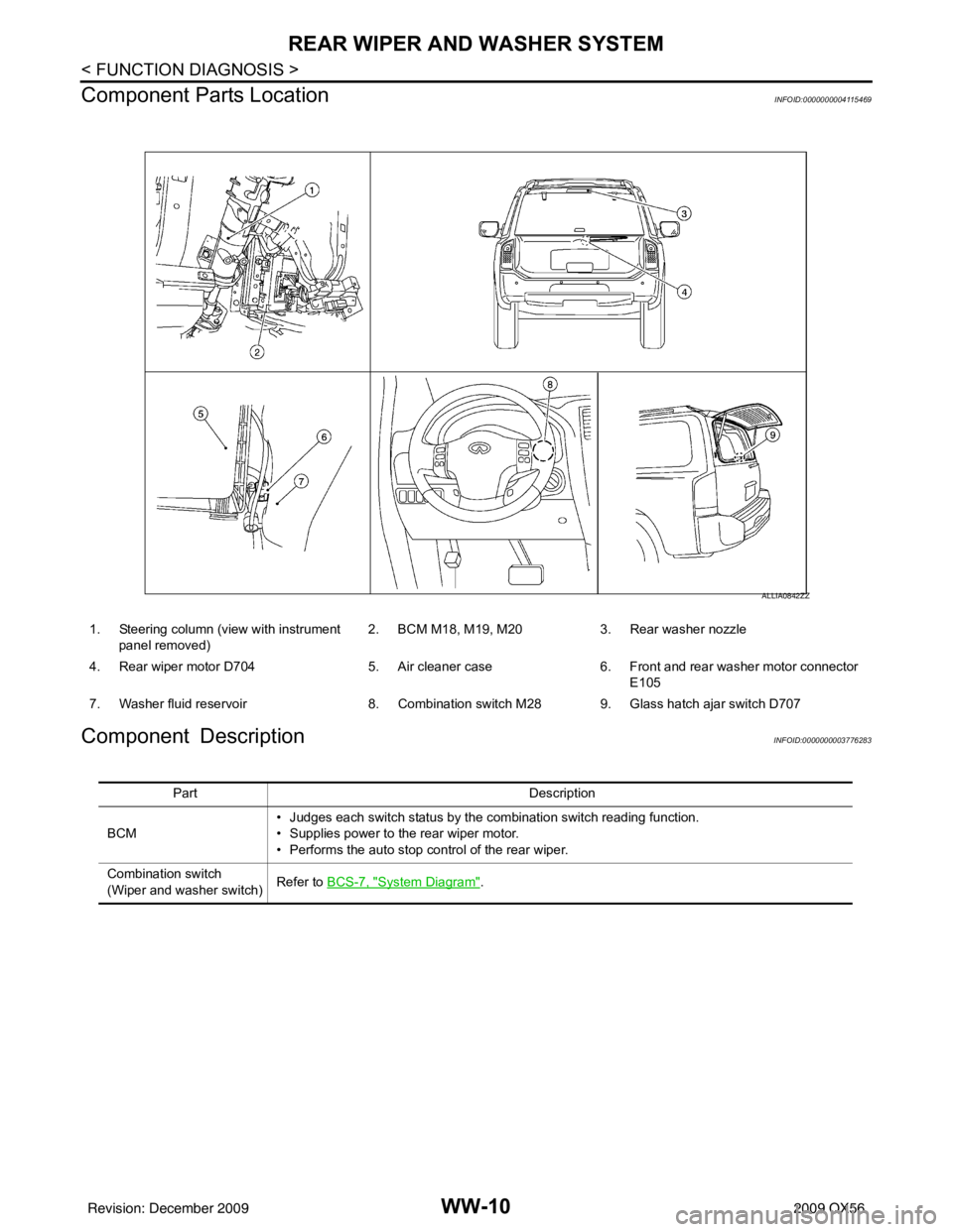
Component Parts Location
INFOID:0000000004115469
Component DescriptionINFOID:0000000003776283
1. Steering column (v iew with instrument
panel removed) 2. BCM M18, M19, M20
3. Rear washer nozzle
4. Rear wiper motor D704 5. Air cleaner case6. Front and rear washer motor connector
E105
7. Washer fluid reservoir 8. Combination switch M28 9. Glass hatch ajar switch D707
ALLIA0842ZZ
Part Description
BCM • Judges each switch status by the combination switch reading function.
• Supplies power to the rear wiper motor.
• Performs the auto stop control of the rear wiper.
Combination switch
(Wiper and washer switch) Refer to BCS-7, "
System Diagram".
Revision: December 20092009 QX56