2009 INFINITI QX56 charging
[x] Cancel search: chargingPage 2278 of 4171
HA-14
< PREPARATION >
PREPARATION
Tool number
(Kent-Moore No.)
Tool nameDescription
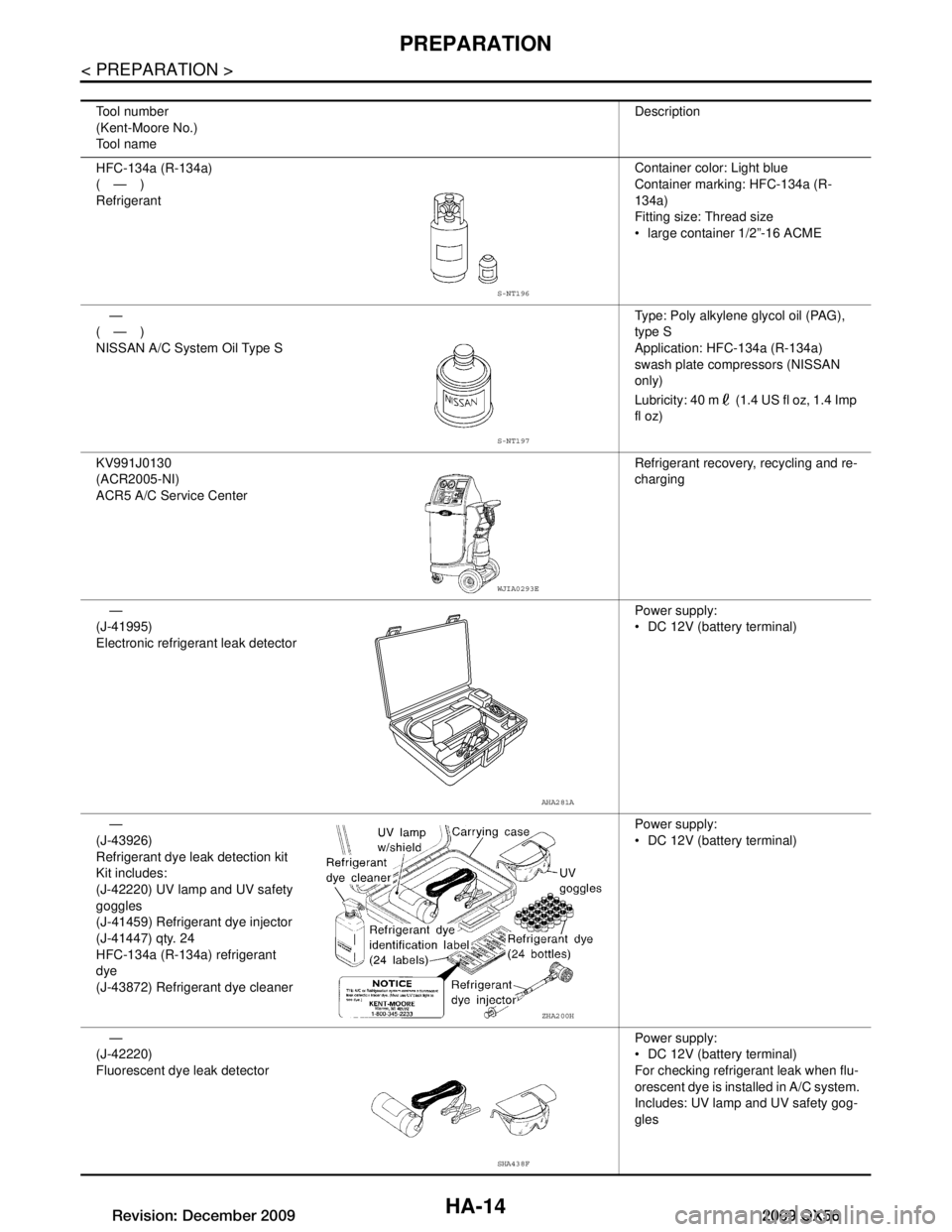
HFC-134a (R-134a)
(—)
Refrigerant Container color: Light blue
Container marking: HFC-134a (R-
134a)
Fitting size: Thread size
large container 1/2”-16 ACME
—
(—)
NISSAN A/C System Oil Type S Type: Poly alkylene glycol oil (PAG),
type S
Application: HFC-134a (R-134a)
swash plate compressors (NISSAN
only)
Lubricity: 40 m (1.4 US fl oz, 1.4 Imp
fl oz)
KV991J0130
(ACR2005-NI)
ACR5 A/C Service Center Refrigerant recovery, recycling and re-
charging
—
(J-41995)
Electronic refrigerant leak detector Power supply:
DC 12V (batte
ry terminal)
—
(J-43926)
Refrigerant dye leak detection kit
Kit includes:
(J-42220) UV lamp and UV safety
goggles
(J-41459) Refrigerant dye injector
(J-41447) qty. 24
HFC-134a (R-134a) refrigerant
dye
(J-43872) Refrigerant dye cleaner Power supply:
DC 12V (batte
ry terminal)
—
(J-42220)
Fluorescent dye leak detector Power supply:
DC 12V (batte
ry terminal)
For checking refrigerant leak when flu-
orescent dye is installed in A/C system.
Includes: UV lamp and UV safety gog-
gles
S-NT196
S-NT197
WJIA0293E
AHA281A
ZHA200H
SHA438F
Revision: December 20092009 QX56
Page 2279 of 4171
PREPARATIONHA-15
< PREPARATION >
C
DE
F
G H
J
K L
M A
B
HA
N
O P
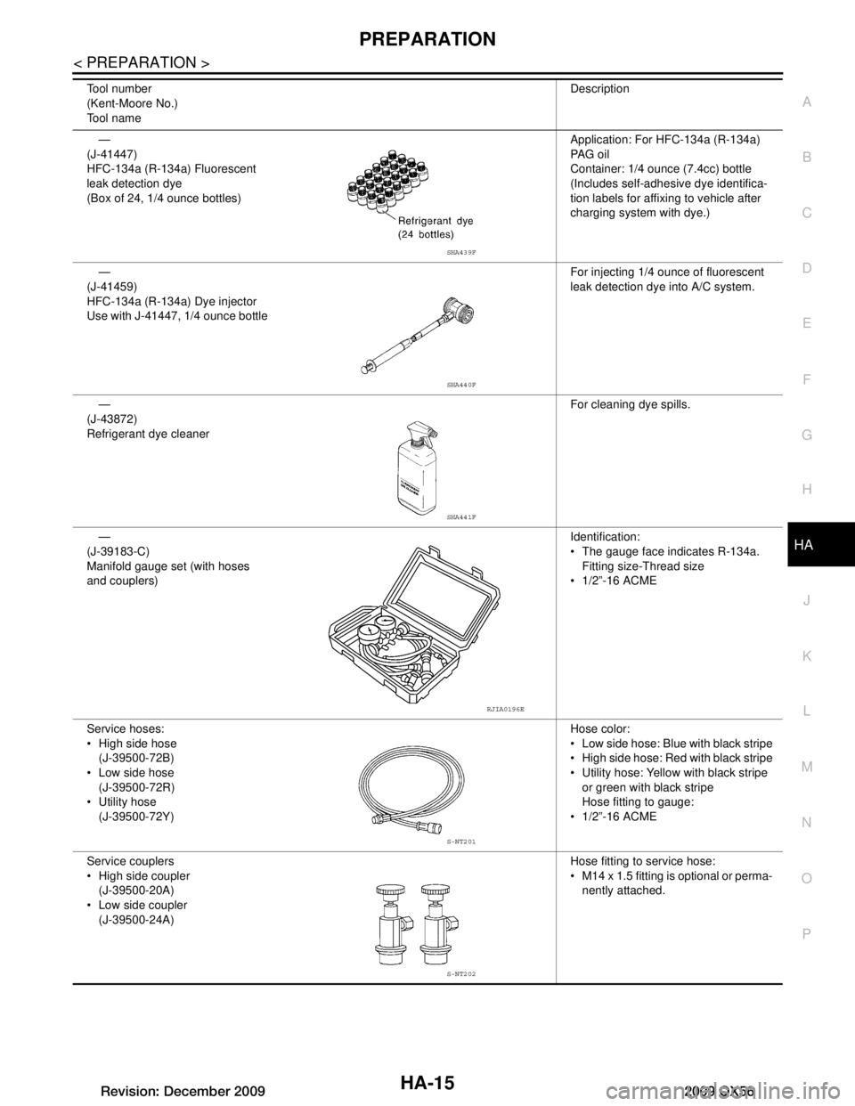
—
(J-41447)
HFC-134a (R-134a) Fluorescent
leak detection dye
(Box of 24, 1/4 ounce bottles) Application: For HFC-134a (R-134a)
PA G o i l
Container: 1/4 ounce (7.4cc) bottle
(Includes self-adhesive dye identifica-
tion labels for affixing to vehicle after
charging system with dye.)
—
(J-41459)
HFC-134a (R-134a) Dye injector
Use with J-41447, 1/4 ounce bottle For injecting 1/4 ounce of fluorescent
leak detection dye into A/C system.
—
(J-43872)
Refrigerant dye cleaner For cleaning dye spills.
—
(J-39183-C)
Manifold gauge set (with hoses
and couplers) Identification:
The gauge face indicates R-134a.
Fitting size-Thread size
1/2”-16 ACME
Service hoses:
High side hose (J-39500-72B)
Low side hose
(J-39500-72R)
Utility hose (J-39500-72Y) Hose color:
Low side hose: Blue with black stripe
High side hose: Red with black stripe
Utility hose: Yellow with black stripe
or green with black stripe
Hose fitting to gauge:
1/2”-16 ACME
Service couplers
High side coupler (J-39500-20A)
Low side coupler (J-39500-24A) Hose fitting to service hose:
M14 x 1.5 fitting is optional or perma-
nently attached.
Tool number
(Kent-Moore No.)
Tool name
Description
SHA439F
SHA440F
SHA441F
RJIA0196E
S-NT201
S-NT202
Revision: December 20092009 QX56
Page 2284 of 4171
HA-20
< ON-VEHICLE MAINTENANCE >
REFRIGERATION SYSTEM
ON-VEHICLE MAINTENANCE
REFRIGERATION SYSTEM
HFC-134a (R-134a) Service ProcedureINFOID:0000000003775301
SETTING OF SERVICE TOOLS AND EQUIPMENT
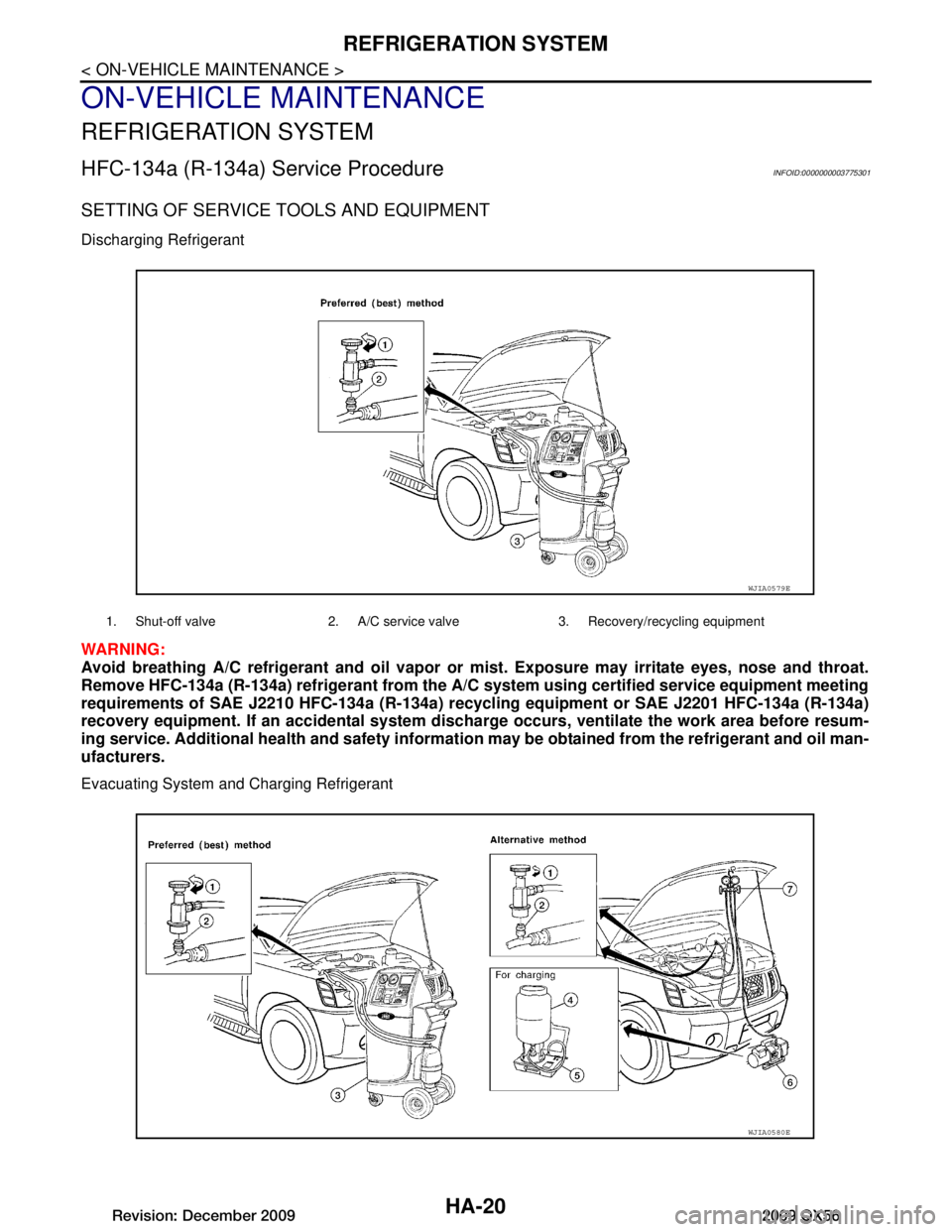
Discharging Refrigerant
WARNING:
Avoid breathing A/C refrigerant and oil vapor or mist. Exposure may irritate eyes, nose and throat.
Remove HFC-134a (R-134a) refrigerant from the A/C system using certified service equipment meeting
requirements of SAE J2210 HFC-134a (R-134a) r ecycling equipment or SAE J2201 HFC-134a (R-134a)
recovery equipment. If an accidental system dischar ge occurs, ventilate the work area before resum-
ing service. Additi onal health and safety information may be ob tained from the refrigerant and oil man-
ufacturers.
Evacuating System and Charging Refrigerant
1. Shut-off valve 2. A/C service valve 3. Recovery/recycling equipment
WJIA0579E
WJIA0580E
Revision: December 20092009 QX56
Page 2287 of 4171
OIL
HA-23
< ON-VEHICLE MAINTENANCE >
C
D E
F
G H
J
K L
M A
B
HA
N
O P
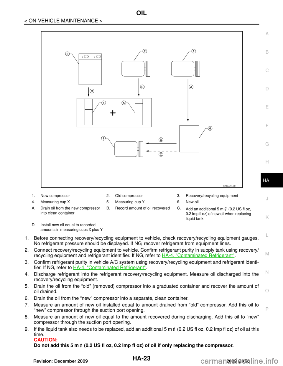
1. Before connecting recovery/recycling equipment to vehicle, check recovery/recycling equipment gauges.
No refrigerant pressure should be displayed. If NG, recover refrigerant from equipment lines.
2. Connect recovery/recycling equipment to vehicle. Confir m refrigerant purity in supply tank using recovery/
recycling equipment and refrigerant identifier. If NG, refer to HA-4, "Contaminated Refrigerant"
.
3. Confirm refrigerant purity in vehicle A/C system using recovery/recycling equipment and refrigerant identi-
fier. If NG, refer to HA-4, "Contaminated Refrigerant"
.
4. Discharge refrigerant into the refrigerant recove ry/recycling equipment. Measure oil discharged into the
recovery/recycling equipment.
5. Drain the oil from the “old” (removed) compress or into a graduated container and recover the amount of
oil drained.
6. Drain the oil from the “new” compressor into a separate, clean container.
7. Measure an amount of new oil installed equal to am ount drained from “old” compressor. Add this oil to
“new” compressor through the suction port opening.
8. Measure an amount of new oil equal to the amount recovered during discharging. Add this oil to “new” compressor through the suction port opening.
9. If the liquid tank also needs to be replaced, add an additional 5 m (0.2 US fl oz, 0.2 Imp fl oz) of oil at this
time.
CAUTION:
Do not add this 5 m (0.2 US fl oz, 0.2 Imp fl oz) of oil if only replacing the compressor.
1. New compressor 2. Old compressor 3. Recovery/recycling equipment
4. Measuring cup X 5. Measuring cup Y 6. New oil
A. Drain oil from the new compressor
into clean container B. Record amount of oil recovered C.
Add an additional 5 m (0.2 US fl oz,
0.2 Imp fl oz) of new oil when replacing
liquid tank
D. Install new oil equal to recorded amounts in measuring cups X plus Y
WJIA1716E
Revision: December 20092009 QX56
Page 2288 of 4171

HA-24
< ON-VEHICLE MAINTENANCE >
FLUORESCENT LEAK DETECTOR
FLUORESCENT LEAK DETECTOR
Checking of Refrigerant LeaksINFOID:0000000003775303
PRELIMINARY CHECK
Perform a visual inspection of all refrigeration parts, fittings, hoses and components for signs of A/C oil leak-
age, damage, and corrosion. Any A/C oil leakage may indicate an area of refrigerant leakage. Allow extra
inspection time in these areas when using either an el ectronic refrigerant leak detector (J-41995) or fluores-
cent dye leak detector (J-42220).
If any dye is observed using a fluor escent dye leak detector (J-42220), c onfirm the leak using a electronic
refrigerant leak detector (J-41995). It is possible that the dye is from a prior leak that was repaired and not
properly cleaned.
When searching for leaks, do not stop when one leak is found but continue to check for additional leaks at all
system components and connections.
When searching for refrigerant leaks using an electroni c refrigerant leak detector (J-41995), move the probe
along the suspected leak area at 25 - 50 mm (1 - 2 in) per second and no further than 6 mm (1/4 in) from the
component.
CAUTION:
Moving the electronic refrigerant l eak detector probe slower and clo ser to the suspected leak area will
improve the chances of finding a leak.
Checking System for L eaks Using the Fluorescent Dye Leak DetectorINFOID:0000000003775304
1. Check the A/C system for leaks using the fluorescent dye leak detector and safety goggles (J-42220) in a
low sunlight area (area without windows preferable). Il luminate all components, fittings and lines. The dye
will appear as a bright green/yellow area at the point of leakage. Fluorescent dye observed at the evapo-
rator drain opening indicates an evaporator core asse mbly leak (tubes, core or expansion valve).
2. If the suspected area is difficult to see, use an adjustable mirror or wipe the area with a clean shop rag or
cloth, then inspect the shop rag or cloth with the fl uorescent dye leak detector (J-42220) for dye residue.
3. After the leak is repaired, remove any residual dye using refrigerant dye cleaner (J-43872) to prevent
future misdiagnosis.
4. Perform a system performance check and then verify t he leak repair using a electronic refrigerant leak
detector (J-41995).
NOTE:
Other gases in the work area or substances on the A/C components, for example, anti-freeze, wind-
shield washer fluid, solvents and oils, may falsely tri gger the leak detector. Make sure the surfaces to be
checked are clean.
Clean with a dry cloth or blow off with shop air.
Do not allow the sensor tip of the electronic refri gerant leak detector (J-41995) to contact with any sub-
stance. This can also cause false readings and may damage the detector.
Dye InjectionINFOID:0000000003775305
NOTE:
This procedure is only necessary when recharging t he system or when the compressor has seized and must
be replaced.
1. Check the A/C system static (at rest) pressure . Pressure must be at least 345 kPa (3.52 kg/cm
2 , 50 psi).
2. Pour one bottle 7.4 cc (1/4 ounce) of the HFC-134a (R -134a) fluorescent leak detection dye (J-41447) into
the HFC-134a (R-134a) dye injector (J-41459).
CAUTION:
If repairing the A/C system or replacing a co mponent, pour the HFC-134a (R-134a) fluorescent leak
detection dye (J-41447) directly into the open system connection and proceed with the service
procedures.
3. Connect the refrigerant dye injector (J- 41459) to the low-pressure service valve.
4. Start the engine and switch the A/C system ON.
5. When the A/C system is operating (compressor runni ng), inject one bottle 7.4 cc (1/4 ounce) of HFC-134a
(R-134a) fluorescent leak detection dye (J-41447) th rough the low-pressure service valve using HFC-
134a (R-134a) dye injector (J-41459). Refer to the manufacturer's operating instructions.
Revision: December 20092009 QX56
Page 2296 of 4171
HA-32
< ON-VEHICLE REPAIR >
COMPRESSOR
Replace the O-rings of the low-pressure flexible hose and high-pressure flexible hose with new
ones, apply compressor oil to the O-rings when installing them.
After recharging the A/C system with refrigerant, check for leaks.
Removal and Installation for Compressor ClutchINFOID:0000000003775310
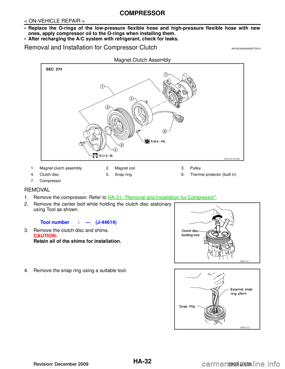
Magnet Clutch Assembly
REMOVAL
1. Remove the compressor. Refer to HA-31, "Removal and Installation for Compressor".
2. Remove the center bolt while holding the clutch disc stationary using Tool as shown.
3. Remove the clutch disc and shims. CAUTION:
Retain all of the shims for installation.
4. Remove the snap ring using a suitable tool.
AWIIA1286GB
1. Magnet clutch assembly 2. Magnet coil 3. Pulley
4. Clutch disc 5. Snap ring 6. Thermal protector (built in)
7. Compressor
Tool number : — (J-44614)
WHA228
RHA072C
Revision: December 20092009 QX56
Page 2300 of 4171
HA-36
< ON-VEHICLE REPAIR >
LOW-PRESSURE FLEXIBLE HOSE
LOW-PRESSURE FLEXIBLE HOSE
Removal and Installation for Low-Pressure Flexible HoseINFOID:0000000003775311
REMOVAL
1. Remove the engine air cleaner and air ducts. Refer to EM-25, "Removal and Installation".
2. Discharge the refrigerant. Refer to HA-20, "HFC-134a (R-134a) Service Procedure"
.
3. Remove the low-pressure flexible hose. CAUTION:
Cap or wrap the joint of the pipe with suitable mate rial such as vinyl tape to avoid the entry of air.
INSTALLATION
Installation is in the reverse order of removal.
Refer to HA-29, "Component"
.
CAUTION:
Replace the O-ring of the low-pr essure flexible hose with a new one, then apply compressor oil to it
when installing it.
After charging refrigerant, check for leaks.
Revision: December 20092009 QX56
Page 2301 of 4171
LOW-PRESSURE PIPEHA-37
< ON-VEHICLE REPAIR >
C
DE
F
G H
J
K L
M A
B
HA
N
O P
LOW-PRESSURE PIPE
Removal and Installation for Low-Pressure PipeINFOID:0000000003775312
REMOVAL
1. Discharge the refrigerant. Refer to HA-20, "HFC-134a (R-134a) Service Procedure".
2. Remove the cowl top and the cowl top extension. Refer to EXT-18, "Removal and Installation"
.
3. Remove the low-pressure pipe. CAUTION:
Cap or wrap the joint of the pipes with suitable material such as viny l tape to avoid the entry of air.
INSTALLATION
Installation is in the reverse order of removal.
Refer to HA-29, "Component"
.
CAUTION:
Replace the O-ring of the high/low-pressure pipe with a new one, then apply compressor oil to it
when installing it.
After charging refrigerant, check for leaks.
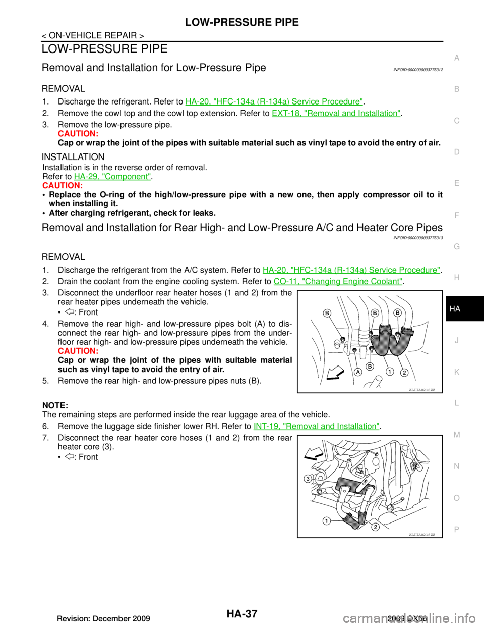
Removal and Installation for Rear High- and Low-Pressure A/C and Heater Core Pipes
INFOID:0000000003775313
REMOVAL
1. Discharge the refrigerant from the A/C system. Refer to HA-20, "HFC-134a (R-134a) Service Procedure".
2. Drain the coolant from the engine cooling system. Refer to CO-11, "Changing Engine Coolant"
.
3. Disconnect the underfloor rear heater hoses (1 and 2) from the rear heater pipes underneath the vehicle.
: Front
4. Remove the rear high- and low-pressure pipes bolt (A) to dis- connect the rear high- and low-pressure pipes from the under-
floor rear high- and low-pressu re pipes underneath the vehicle.
CAUTION:
Cap or wrap the joint of the pipes with suitable material
such as vinyl tape to avoid the entry of air.
5. Remove the rear high- and low-pressure pipes nuts (B).
NOTE:
The remaining steps are performed inside the rear luggage area of the vehicle.
6. Remove the luggage side finisher lower RH. Refer to INT-19, "Removal and Installation"
.
7. Disconnect the rear heater core hoses (1 and 2) from the rear heater core (3).
: Front
ALIIA0216ZZ
ALIIA0218ZZ
Revision: December 20092009 QX56