2009 INFINITI QX56 warning
[x] Cancel search: warningPage 3195 of 4171

SCS-2
EXHAUST VALVE SOLENOID CIRCUIT ..........23
Description ........................................................... ...23
Component Function Check ...................................23
Diagnosis Procedure ..............................................23
CK SUSP WARNING INDICATOR CONTROL
CIRCUIT .............................................................
25
Description ........................................................... ...25
Component Function Check ...................................25
Diagnosis Procedure ..............................................25
ECU DIAGNOSIS ..................................... ...27
SUSPENSION CONTROL UNIT ........................27
Reference Value .................................................. ...27
Wiring Diagram .......................................................28
DTC Index ..............................................................33
SYMPTOM DIAGNOSIS .............................35
SUSPENSION CONTROL SYSTEM .............. ...35
Symptom Table ................................................... ...35
SUSPENSION CONTROL SYSTEM INOPER-
ATIVE .................................................................
36
Description ........................................................... ...36
Diagnosis Procedure ...............................................36
SUSPENSION CONTROL SYSTEM DOES
NOT RAISE ........................................................
37
Description ........................................................... ...37
Diagnosis Procedure ...............................................37
SUSPENSION CONTROL SYSTEM DOES
NOT LOWER .....................................................
38
Description ........................................................... ...38
Diagnosis Procedure ...............................................38
PRECAUTION ............................................39
PRECAUTIONS .............................................. ...39
Precaution for Supplemental Restraint System
(SRS) "AIR BAG" and "SEAT BELT PRE-TEN-
SIONER" .............................................................. ...
39
Precaution for Rear Suspension .............................39
Revision: December 20092009 QX56
Page 3201 of 4171

SCS-8
< FUNCTION DIAGNOSIS >
DIAGNOSIS SYSTEM (SUSPENSION CONTROL UNIT)
CAUTION:
The "COMPRESSOR active test will remain ON until it is turned off using CONSULT-III. Allowing the
compressor to run for an extended period of time may cause damage to the suspension control sys-
tem components due to excessive pressure.
NOTE:
• "TEST IS STOPPED" is displayed approximately 10 seconds after operation starts for all active test items except "COMPRESSOR".
• After "TEST IS STOPPED" is display ed, to perform test again, repeat step 6.
EXHAUST SOLENOID ON/OFF
WARNING LAMP ON/OFF
Revision: December 20092009 QX56
Page 3218 of 4171
CK SUSP WARNING INDICATOR CONTROL CIRCUITSCS-25
< COMPONENT DIAGNOSIS >
C
DF
G H
I
J
K L
M A
B
SCS
N
O P
CK SUSP WARNING INDICATOR CONTROL CIRCUIT
DescriptionINFOID:0000000003772348
The CK SUSP warning lamp is controlled by a ground signal provided to the combination meter by the sus-
pension control unit.
Component Function CheckINFOID:0000000003772349
1.CHECK WARNING LAMP OPERATION
CONSULT-III
1. Turn ignition ON.
2. Select "WARNING LAMP" of AI R LEVELIZER active test items.
3. While operating test item, check that the warning lamp activates.
Does the warning lamp operate properly?
YES >> Warning lamp is operating normally.
NO >> Refer to SCS-25, "
Diagnosis Procedure".
Diagnosis ProcedureINFOID:0000000003772350
1.PERFORM SUSPENSION CONTROL SYSTEM SELF-DIAGNOSIS
CONSULT-III
1. Turn ignition ON.
2. Perform SELF DIAGNOSIS function of AIR LEVELIZER system.
Are any DTC's present?
YES >> Refer to SCS-33, "DTC Index".
NO >> • If warning lamp is always ON, GO TO 2. • If warning lamp is always OFF, GO TO 3
2.CHECK SUSPENSION CONTROL UNIT WARNING LAMP CONTROL
1. Turn ignition OFF.
2. Disconnect the suspension control unit connector B3.
3. Turn ignition ON.
Does the CK SUSP warning lamp turn ON?
YES >> GO TO 3.
NO >> Replace the suspension control unit. Refer to RSU-26, "
Removal and Installation".
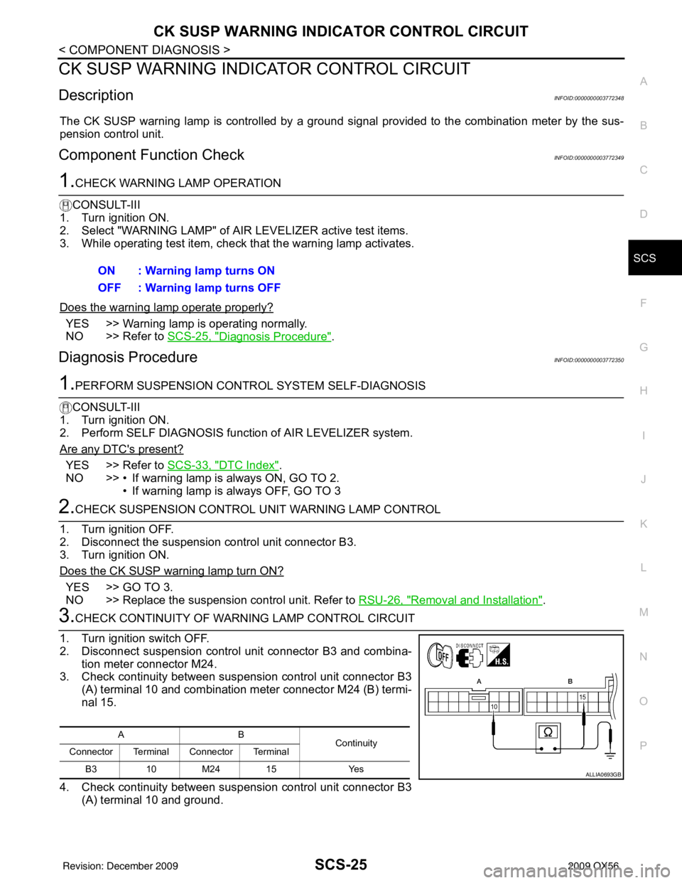
3.CHECK CONTINUITY OF WARNING LAMP CONTROL CIRCUIT
1. Turn ignition switch OFF.
2. Disconnect suspension control unit connector B3 and combina- tion meter connector M24.
3. Check continuity between suspension control unit connector B3 (A) terminal 10 and combination meter connector M24 (B) termi-
nal 15.
4. Check continuity between suspension control unit connector B3 (A) terminal 10 and ground.ON : Warning lamp turns ON
OFF : Warning lamp turns OFF
AB
Continuity
Connector Terminal Connector Terminal
B3 10 M24 15 Yes
ALLIA0693GB
Revision: December 20092009 QX56
Page 3219 of 4171

SCS-26
< COMPONENT DIAGNOSIS >
CK SUSP WARNING INDICATOR CONTROL CIRCUIT
Are the continuity test results as specified?
YES >> Replace the combination meter. Refer to MWI-102, "Removal and Installation".
NO >> Repair harness or connector.
A —Continuity
Connector Terminal
B3 10Ground No
Revision: December 20092009 QX56
Page 3220 of 4171
SUSPENSION CONTROL UNITSCS-27
< ECU DIAGNOSIS >
C
DF
G H
I
J
K L
M A
B
SCS
N
O P
ECU DIAGNOSIS
SUSPENSION CONTROL UNIT
Reference ValueINFOID:0000000003772351
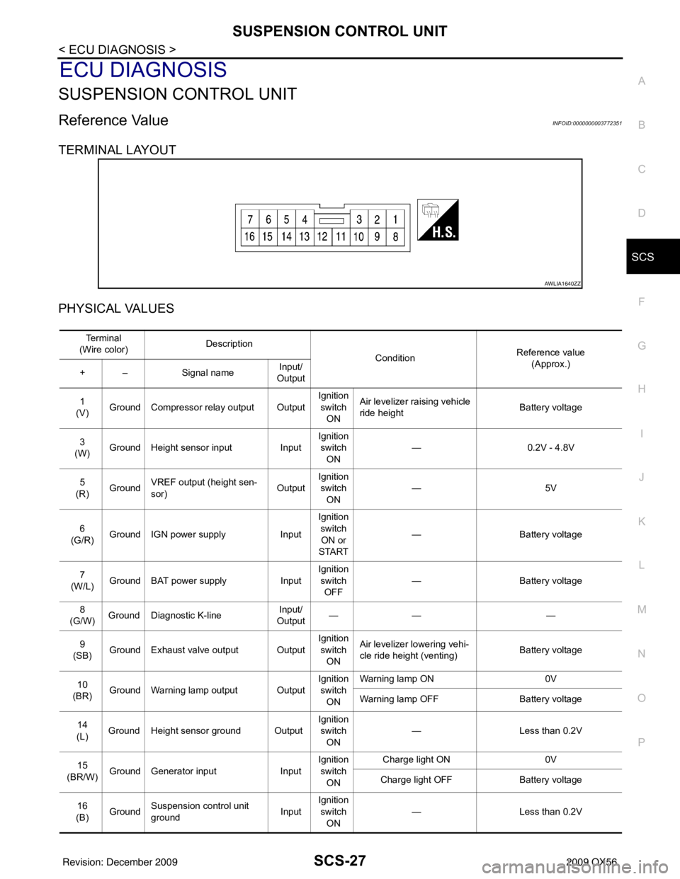
TERMINAL LAYOUT
PHYSICAL VALUES
AWLIA1640ZZ
Te r m i n a l
(Wire color) Description
ConditionReference value
(Approx.)
+ – Signal nameInput/
Output
1
(V) Ground Compressor relay output Output Ignition
switch ON Air levelizer ra
ising vehicle
ride height Battery voltage
3
(W) Ground Height sensor input
InputIgnition
switch
ON —
0.2V - 4.8V
5
(R) Ground VREF output (height sen-
sor)
OutputIgnition
switch ON —5
V
6
(G/R) Ground IGN power supply
InputIgnition
switch ON or
START —
Battery voltage
7
(W/L) Ground BAT power supply
InputIgnition
switch OFF —
Battery voltage
8
(G/W) Ground Diagnostic K-line Input/
Output ——
—
9
(SB) Ground Exhaust valve output Output Ignition
switch ON Air levelizer lo
wering vehi-
cle ride height (venting) Battery voltage
10
(BR) Ground Warning lamp output Output Ignition
switch
ON Warning lamp ON
0V
Warning lamp OFF Battery voltage
14
(L) Ground Height sensor ground Output Ignition
switch ON —
Less than 0.2V
15
(BR/W) Ground Generator input
InputIgnition
switch ON Charge light ON
0V
Charge light OFF Battery voltage
16
(B) Ground
Suspension control unit
ground InputIgnition
switch
ON —
Less than 0.2V
Revision: December 20092009 QX56
Page 3232 of 4171
PRECAUTIONSSCS-39
< PRECAUTION >
C
DF
G H
I
J
K L
M A
B
SCS
N
O P
PRECAUTION
PRECAUTIONS
Precaution for Supplemental Restraint System (SRS) "AIR BAG" and "SEAT BELT
PRE-TENSIONER"
INFOID:0000000005867805
The Supplemental Restraint System such as “AIR BAG” and “SEAT BELT PRE-TENSIONER”, used along
with a front seat belt, helps to reduce the risk or severi ty of injury to the driver and front passenger for certain
types of collision. This system includes seat belt switch inputs and dual stage front air bag modules. The SRS
system uses the seat belt switches to determine the front air bag deployment, and may only deploy one front
air bag, depending on the severity of a collision and w hether the front occupants are belted or unbelted.
Information necessary to service the system safely is included in the SR and SB section of this Service Man-
ual.
WARNING:
• To avoid rendering the SRS inoper ative, which could increase the risk of personal injury or death in
the event of a collision which would result in air bag inflation, all maintenance must be performed by
an authorized NISSAN/INFINITI dealer.
• Improper maintenance, including in correct removal and installation of the SRS, can lead to personal
injury caused by unintentional act ivation of the system. For removal of Spiral Cable and Air Bag
Module, see the SR section.
• Do not use electrical test equipm ent on any circuit related to the SRS unless instructed to in this
Service Manual. SRS wiring harnesses can be identi fied by yellow and/or orange harnesses or har-
ness connectors.
PRECAUTIONS WHEN USING POWER TOOLS (AIR OR ELECTRIC) AND HAMMERS
WARNING:
• When working near the Airbag Diagnosis Sensor Un it or other Airbag System sensors with the Igni-
tion ON or engine running, DO NOT use air or el ectric power tools or strike near the sensor(s) with a
hammer. Heavy vibration could activate the sensor( s) and deploy the air bag(s), possibly causing
serious injury.
• When using air or electric power tools or hammers, always switch the Ignition OFF, disconnect the battery, and wait at least 3 minutes before performing any service.
Precaution for Rear SuspensionINFOID:0000000003772362
• When installing the rubber bushings, the final tightening must be done under unladen condition and with thetires on level ground. Oil will shorten the life of the rubber bushings, so wipe off any spilled oil immediately.
• Unladen condition means the fuel tank, engine coolant and lubricants are at the full specification. The spare tire, jack, hand tools, and mats are in their designated positions.
• After installing suspension components, check the wheel alignment.
• Caulking nuts are not reusable. Always use new caulking nuts for installation. New caulking nuts are pre-
oiled, do not apply any additional lubrication.
Revision: December 20092009 QX56
Page 3276 of 4171
SE-44
< PRECAUTION >
PRECAUTIONS
PRECAUTION
PRECAUTIONS
Precaution for Supplemental Restraint System (SRS) "AIR BAG" and "SEAT BELT
PRE-TENSIONER"
INFOID:0000000005880168
The Supplemental Restraint System such as “A IR BAG” and “SEAT BELT PRE-TENSIONER”, used along
with a front seat belt, helps to reduce the risk or severity of injury to the driver and front passenger for certain
types of collision. This system includes seat belt switch inputs and dual stage front air bag modules. The SRS
system uses the seat belt switches to determine the front air bag deployment, and may only deploy one front
air bag, depending on the severity of a collision and w hether the front occupants are belted or unbelted.
Information necessary to service the system safely is included in the SR and SB section of this Service Man-
ual.
WARNING:
• To avoid rendering the SRS inopera tive, which could increase the risk of personal injury or death in
the event of a collision which would result in air bag inflation, all maintenance must be performed by
an authorized NISSAN/INFINITI dealer.
• Improper maintenance, including in correct removal and installation of the SRS, can lead to personal
injury caused by unintent ional activation of the system. For re moval of Spiral Cable and Air Bag
Module, see the SR section.
• Do not use electrical test equipmen t on any circuit related to the SRS unless instructed to in this
Service Manual. SRS wiring harn esses can be identified by yellow and/or orange harnesses or har-
ness connectors.
PRECAUTIONS WHEN USING POWER TOOLS (AIR OR ELECTRIC) AND HAMMERS
WARNING:
• When working near the Airbag Diagnosis Sensor Unit or other Airbag System sensors with the Igni-
tion ON or engine running, DO NOT use air or electri c power tools or strike near the sensor(s) with a
hammer. Heavy vibration could activate the sensor( s) and deploy the air bag(s), possibly causing
serious injury.
• When using air or electric power tools or hammers , always switch the Ignition OFF, disconnect the
battery, and wait at least 3 minu tes before performing any service.
Precaution Necessary for Steering W heel Rotation After Battery Disconnect
INFOID:0000000005889885
NOTE:
• This Procedure is applied only to models with Intelligent Key system and NATS (NISSAN ANTI-THEFT SYS-
TEM).
• Remove and install all control units after disconnecting both battery cables with the ignition knob in the
″LOCK ″ position.
• Always use CONSULT-III to perform self-diagnosis as a part of each function inspection after finishing work.
If DTC is detected, perform trouble diagnosis according to self-diagnostic results.
For models equipped with the Intelligent Key system and NATS, an electrically controlled steering lock mech-
anism is adopted on the key cylinder.
For this reason, if the battery is disconnected or if the battery is discharged, the steering wheel will lock and
steering wheel rotation will become impossible.
If steering wheel rotation is required when battery pow er is interrupted, follow the procedure below before
starting the repair operation.
OPERATION PROCEDURE
1. Connect both battery cables. NOTE:
Supply power using jumper cables if battery is discharged.
2. Use the Intelligent Key or mechanical key to turn the ignition switch to the ″ACC ″ position. At this time, the
steering lock will be released.
3. Disconnect both battery cables. The steering lock will remain released and the steering wheel can be rotated.
4. Perform the necessary repair operation.
Revision: December 20092009 QX56
Page 3300 of 4171
SE-68
< DISASSEMBLY AND ASSEMBLY >
FRONT SEAT
Disassembly and Assembly
INFOID:0000000003775483
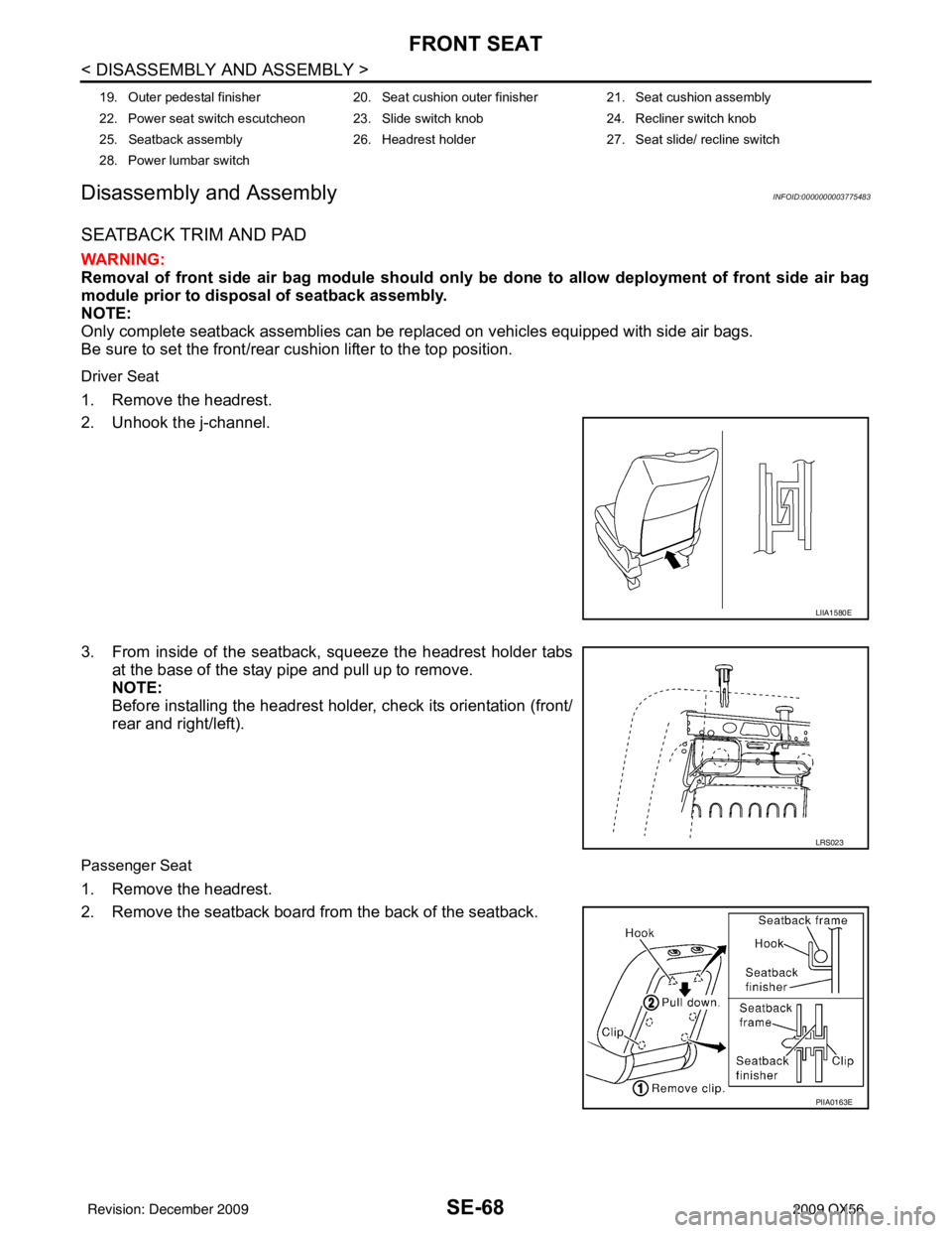
SEATBACK TRIM AND PAD
WARNING:
Removal of front side air bag module should only be done to allow deployment of front side air bag
module prior to disposal of seatback assembly.
NOTE:
Only complete seatback assemblies can be replaced on vehicles equipped with side air bags.
Be sure to set the front/rear cushion lifter to the top position.
Driver Seat
1. Remove the headrest.
2. Unhook the j-channel.
3. From inside of the seatback, squeeze the headrest holder tabs at the base of the stay pipe and pull up to remove.
NOTE:
Before installing the headrest holder, check its orientation (front/
rear and right/left).
Passenger Seat
1. Remove the headrest.
2. Remove the seatback board from the back of the seatback.
19. Outer pedestal finisher 20. Seat cushion outer finisher21. Seat cushion assembly
22. Power seat switch escutcheon 23. Slide switch knob 24. Recliner switch knob
25. Seatback assembly 26. Headrest holder27. Seat slide/ recline switch
28. Power lumbar switch
LIIA1580E
LRS023
PIIA0163E
Revision: December 20092009 QX56