2009 INFINITI QX56 electric
[x] Cancel search: electricPage 2560 of 4171
IP-16
< ON-VEHICLE REPAIR >
CLUSTER LID C
CLUSTER LID C
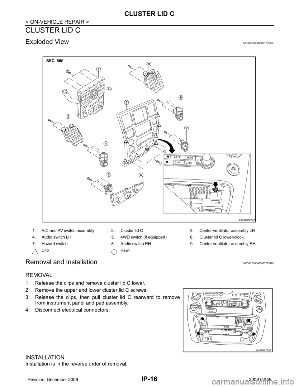
Exploded ViewINFOID:0000000003775425
Removal and InstallationINFOID:0000000003775426
REMOVAL
1. Release the clips and remove cluster lid C lower.
2. Remove the upper and lower cluster lid C screws.
3. Release the clips, then pull cluster lid C rearward to removefrom instrument panel and pad assembly.
4. Disconnect electrical connectors.
INSTALLATION
Installation is in the reverse order of removal.
1. A/C and AV switch assembly 2. Cluster lid C 3. Center ventilator assembly LH
4. Audio switch LH 5. 4WD switch (if equipped)6. Cluster lid C lower/clock
7. Hazard switch 8. Audio switch RH9. Center ventilator assembly RH
Clip Pawl
AWJIA0237ZZ
ALJIA0078ZZ
Revision: December 20092009 QX56
Page 2563 of 4171
A/T FINISHERIP-19
< ON-VEHICLE REPAIR >
C
DE
F
G H
I
K L
M A
B
IP
N
O P
A/T FINISHER
Removal and InstallationINFOID:0000000003775431
REMOVAL
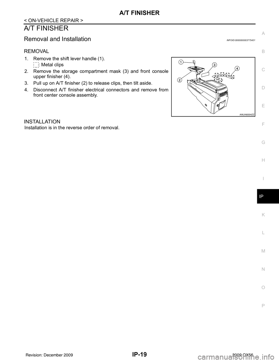
1. Remove the shift lever handle (1). : Metal clips
2. Remove the storage compartment mask (3) and front console upper finisher (4).
3. Pull up on A/T finisher (2) to release clips, then tilt aside.
4. Disconnect A/T finisher electrical connectors and remove from front center console assembly.
INSTALLATION
Installation is in the reverse order of removal.
AWJIA0004ZZ
Revision: December 20092009 QX56
Page 2564 of 4171
IP-20
< ON-VEHICLE REPAIR >
FRONT CENTER CONSOLE
FRONT CENTER CONSOLE
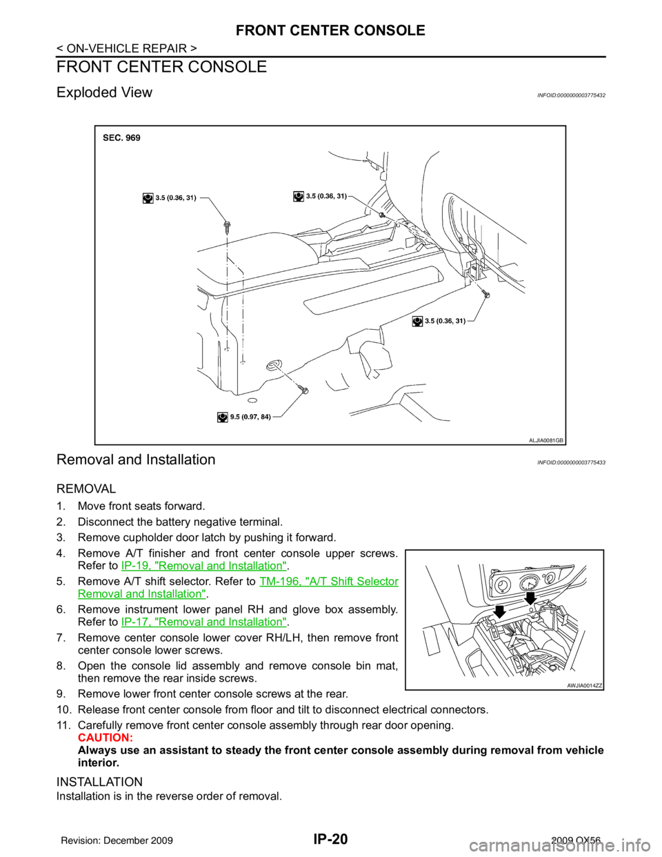
Exploded ViewINFOID:0000000003775432
Removal and InstallationINFOID:0000000003775433
REMOVAL
1. Move front seats forward.
2. Disconnect the battery negative terminal.
3. Remove cupholder door latch by pushing it forward.
4. Remove A/T finisher and front center console upper screws.Refer to IP-19, "
Removal and Installation".
5. Remove A/T shift selector. Refer to TM-196, "
A/T Shift Selector
Removal and Installation".
6. Remove instrument lower panel RH and glove box assembly. Refer to IP-17, "
Removal and Installation".
7. Remove center console lower cover RH/LH, then remove front center console lower screws.
8. Open the console lid assembly and remove console bin mat, then remove the rear inside screws.
9. Remove lower front center console screws at the rear.
10. Release front center console from floor and tilt to disconnect electrical connectors.
11. Carefully remove front center console assembly through rear door opening. CAUTION:
Always use an assistant to steady the front cen ter console assembly during removal from vehicle
interior.
INSTALLATION
Installation is in the reverse order of removal.
ALJIA0081GB
AWJIA0014ZZ
Revision: December 20092009 QX56
Page 2567 of 4171
FRONT CENTER CONSOLEIP-23
< DISASSEMBLY AND ASSEMBLY >
C
DE
F
G H
I
K L
M A
B
IP
N
O P
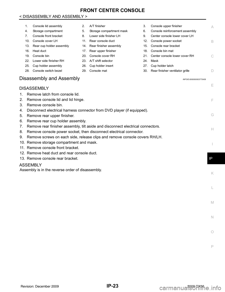
Disassembly and AssemblyINFOID:0000000003775436
DISASSEMBLY
1. Remove latch from console lid.
2. Remove console lid and lid hinge.
3. Remove console bin.
4. Disconnect electrical harness connec tor from DVD player (if equipped).
5. Remove rear upper finisher.
6. Remove rear cup holder assembly.
7. Remove rear finisher assembly, tilt aside and disconnect electrical connectors.
8. Remove console power socket, then disconnect electrical connector.
9. Remove screws on each side, release clips and remove console covers RH/LH.
10. Remove storage compartment and mask.
11. Remove console front bracket.
12. Remove heat duct and rear console duct.
13. Remove console rear bracket.
ASSEMBLY
Assembly is in the reverse order of disassembly.
1. Console lid assembly 2. A/T finisher 3. Console upper finisher
4. Storage compartment 5. Storage compartment mask 6. Console reinforcement assembly
7. Console front bracket 8. Lower side finisher LH 9. Center console lower cover LH
10. Console cover LH 11. Rear console duct 12. Console power socket
13. Rear cup holder assembly 14. Rear finisher assembly 15. Console rear bracket
16. Heat duct 17. Rear upper finisher 18. Console bin mat
19. Console bin 20. Console cover RH 21. Center console lower cover RH
22. Lower side finisher RH 23. A/T shift selector 24. Mask
25. Cup holder assembly 26. Cup holder insert 27. Cup holder latch
28. Console switch bezel 29. Console mat 30. Rear finisher ventilator grille
Revision: December 20092009 QX56
Page 2570 of 4171
LAN
LAN-1
ELECTRICAL & POWER CONTROL
C
DE
F
G H
I
J
K L
B
SECTION LAN
A
O P
N
CONTENTS
LAN SYSTEM
CAN FUNDAMENTAL
PRECAUTION ....... ........................................
3
PRECAUTIONS .............................................. .....3
Precaution for Trouble Diagnosis ........................ ......3
Precaution for Harness Repair ..................................3
FUNCTION DIAGNOSIS .. .............................4
CAN COMMUNICATION SYSTEM ................ .....4
System Description ............................................. ......4
System Diagram ........................................................4
CAN Communication Control Circuit .........................5
DIAG ON CAN .....................................................6
Description .......................................................... ......6
System Diagram ........................................................6
TROUBLE DIAGNOSIS ......................................7
Condition of Error Detection ................................ ......7
Symptom When Error Occurs in CAN Communi-
cation System ...................................................... ......
7
Self-Diagnosis .........................................................10
CAN Diagnostic Support Monitor ............................10
BASIC INSPECTION ...................................13
DIAGNOSIS AND REPAIR WORKFLOW ..... ....13
Information Needed for Trouble Diagnosis ......... ....13
How to Use CAN Communication Signal Chart ......13
Trouble Diagnosis Flow Chart .................................14
Trouble Diagnosis Procedure ..................................14
CAN
HOW TO USE THIS MANU AL .....................
36
HOW TO USE THIS SECTION ....................... ....36
Caution ................................................................ ....36
Abbreviation List ......................................................36
PRECAUTION ..............................................37
PRECAUTIONS .................................................37
Precaution for Supplemental Restraint System
(SRS) "AIR BAG" and "SEAT BELT PRE-TEN-
SIONER" ............................................................. ....
37
Precautions for Trouble Diagnosis ..........................37
Precautions for Harness Repair ..............................37
BASIC INSPECTION ...................................39
DIAGNOSIS AND REPAIR WORKFLOW ........39
Interview Sheet .................................................... ....39
Diagnosis Sheet (CAN Type 1) ...............................40
Diagnosis Sheet (CAN Type 2) ...............................41
Diagnosis Sheet (CAN Type 3) ...............................42
Diagnosis Sheet (CAN Type 4) ...............................43
FUNCTION DIAGNOSIS ..............................44
CAN COMMUNICATION SYSTEM ...................44
CAN System Specification Chart ......................... ....44
CAN Communication Signal Chart ..........................44
TROUBLE DIAGNOSIS ....................................47
CAN Diagnostic Support Monitor .............................47
DTC Index ...............................................................51
COMPONENT DIAGNOSIS .........................52
CAN COMMUNICATION SYSTEM ...................52
Component Parts Location .................................. ....52
Wiring Diagram - CAN SYSTEM - ...........................53
MALFUNCTION AREA CHART ........................60
Main Line ............................................................. ....60
Branch Line .............................................................60
Short Circuit .............................................................60
MAIN LINE BETWEEN TCM AND ADP CIR-
CUIT ..................................................................
61
Diagnosis Procedure ...............................................61
Revision: December 20092009 QX56
Page 2573 of 4171
![INFINITI QX56 2009 Factory Service Manual LAN-4
< FUNCTION DIAGNOSIS >[CAN FUNDAMENTAL]
CAN COMMUNICATION SYSTEM
FUNCTION DIAGNOSIS
CAN COMMUNICATION SYSTEM
System DescriptionINFOID:0000000003776430
• CAN communication is a multiplex commun INFINITI QX56 2009 Factory Service Manual LAN-4
< FUNCTION DIAGNOSIS >[CAN FUNDAMENTAL]
CAN COMMUNICATION SYSTEM
FUNCTION DIAGNOSIS
CAN COMMUNICATION SYSTEM
System DescriptionINFOID:0000000003776430
• CAN communication is a multiplex commun](/manual-img/42/57031/w960_57031-2572.png)
LAN-4
< FUNCTION DIAGNOSIS >[CAN FUNDAMENTAL]
CAN COMMUNICATION SYSTEM
FUNCTION DIAGNOSIS
CAN COMMUNICATION SYSTEM
System DescriptionINFOID:0000000003776430
• CAN communication is a multiplex communication system. This enables the system to transmit and receive
large quantities of data at high speed by connecting c ontrol units with two communication lines (CAN-H and
CAN-L).
• Control units on the CAN network transmit signals us ing the CAN communication control circuit. They
receive only necessary signals from other c ontrol units to operate various functions.
• CAN communication lines adopt twisted-pair line st yle (two lines twisted) for noise immunity.
System DiagramINFOID:0000000003776431
Each control unit passes an electric current to the termination circuits when transmitting CAN communication
signal. The termination circuits produce an electrical potential difference between CAN-H and CAN-L. CAN
communication system transmits and receives CAN communication signals by the potential difference.
SKIB8887E
Component Description
Main line CAN communication line between splices
Branch line CAN communication line between splice and a control unit
Splice A point connecting a branch line with a main line
Termination circuit Refer to LAN-5, "
CAN Communication Control Circuit".
Revision: December 20092009 QX56
Page 2577 of 4171
![INFINITI QX56 2009 Factory Service Manual LAN-8
< FUNCTION DIAGNOSIS >[CAN FUNDAMENTAL]
TROUBLE DIAGNOSIS
Example: Data link connector branch line open circuit
NOTE:
• When data link connector branch line is open, transmission and reception INFINITI QX56 2009 Factory Service Manual LAN-8
< FUNCTION DIAGNOSIS >[CAN FUNDAMENTAL]
TROUBLE DIAGNOSIS
Example: Data link connector branch line open circuit
NOTE:
• When data link connector branch line is open, transmission and reception](/manual-img/42/57031/w960_57031-2576.png)
LAN-8
< FUNCTION DIAGNOSIS >[CAN FUNDAMENTAL]
TROUBLE DIAGNOSIS
Example: Data link connector branch line open circuit
NOTE:
• When data link connector branch line is open, transmission and reception of CAN communication signals
are not affected. Therefore, no symptoms occur. However, be sure to repair malfunctioning circuit.
• When data link connector branch line is open, “ECU list” displayed on the CONSULT-III “CAN DIAG SUP- PORT MNTR” may be the same as when the CAN communication line has short-circuit. However, symp-
toms differ depending on the case. See below chart for the differences.
EPS control unit Normal operation.
Combination meter • Shift position indicator and OD OFF indicator turn OFF.
• Warning lamps turn ON.
ABS actuator and electric unit (control unit) Normal operation.
TCM No impact on operation.
IPDM E/R Normal operation.
Unit name
Symptom
SKIB8739E
Unit nameSymptom
ECM
Normal operation.
BCM
EPS control unit
Combination meter
ABS actuator and electric unit (control unit)
TCM
IPDM E/R
“ECU list” on the “CAN DIAG SUPPORT MNTR”(CONSULT-III) Difference of symptom
Data link connector branch line open circuit All Diag on CAN units are not
indicated.Normal operation.
CAN-H, CAN-L harness short-circuit Most of the units which are connected to the CAN
communication system enter fail-safe mode or are
deactivated.
Revision: December 20092009 QX56
Page 2578 of 4171
![INFINITI QX56 2009 Factory Service Manual LAN
TROUBLE DIAGNOSISLAN-9
< FUNCTION DIAGNOSIS > [CAN FUNDAMENTAL]
C
D
E
F
G H
I
J
K L
B A
O P
N
Example: Main Line Between Data Link Connector and ABS Actuator and Electr
ic Unit (Control Unit) Open INFINITI QX56 2009 Factory Service Manual LAN
TROUBLE DIAGNOSISLAN-9
< FUNCTION DIAGNOSIS > [CAN FUNDAMENTAL]
C
D
E
F
G H
I
J
K L
B A
O P
N
Example: Main Line Between Data Link Connector and ABS Actuator and Electr
ic Unit (Control Unit) Open](/manual-img/42/57031/w960_57031-2577.png)
LAN
TROUBLE DIAGNOSISLAN-9
< FUNCTION DIAGNOSIS > [CAN FUNDAMENTAL]
C
D
E
F
G H
I
J
K L
B A
O P
N
Example: Main Line Between Data Link Connector and ABS Actuator and Electr
ic Unit (Control Unit) Open Circuit
Example: CAN-H, CAN-L Harness Short Circuit
SKIB8740E
Unit name Symptom
ECM Engine torque limiting is affected, and shift harshness increases.
BCM • Reverse warning chime does not sound.
• The front wiper moves under continuous operation mode even though the front wip-
er switch being in the intermittent position.
EPS control unit The steering effort increases.
Combination meter • The shift position indicator and OD OFF indicator turn OFF.
• The speedometer is inoperative.
• The odo/trip meter stops.
ABS actuator and electric unit (control unit) Normal operation.
TCM No impact on operation.
IPDM E/R When the ignition switch is ON,
• The headlamps (Lo) turn ON.
• The cooling fan continues to rotate.
SKIB8741E
Revision: December 20092009 QX56