2009 INFINITI QX56 lock
[x] Cancel search: lockPage 1917 of 4171
EM-94
< DISASSEMBLY AND ASSEMBLY >
ENGINE UNIT
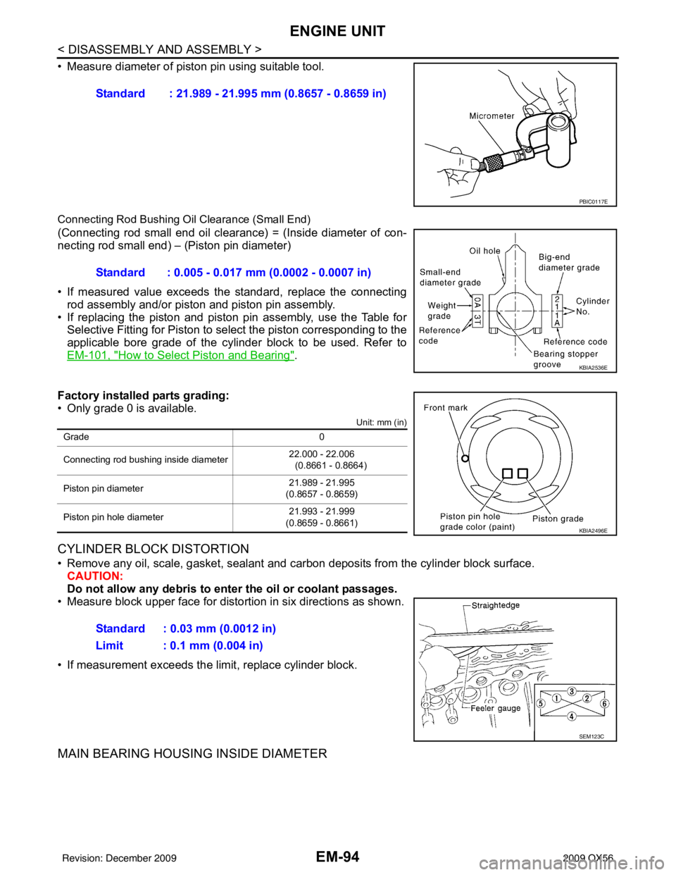
• Measure diameter of piston pin using suitable tool.
Connecting Rod Bushing Oil Clearance (Small End)
(Connecting rod small end oil clearance) = (Inside diameter of con-
necting rod small end) – (Piston pin diameter)
• If measured value exceeds the standard, replace the connectingrod assembly and/or piston and piston pin assembly.
• If replacing the piston and piston pin assembly, use the Table for
Selective Fitting for Piston to select the piston corresponding to the
applicable bore grade of the cylinder block to be used. Refer to
EM-101, "
How to Select Piston and Bearing".
Factory installed parts grading:
• Only grade 0 is available.
Unit: mm (in)
CYLINDER BLOCK DISTORTION
• Remove any oil, scale, gasket, sealant and carbon deposits from the cylinder block surface.
CAUTION:
Do not allow any debris to en ter the oil or coolant passages.
• Measure block upper face for distortion in six directions as shown.
• If measurement exceeds the limit, replace cylinder block.
MAIN BEARING HOUSING INSIDE DIAMETER
Standard : 21.989 - 21.995 mm (0.8657 - 0.8659 in)
PBIC0117E
Standard : 0.005 - 0.017 mm (0.0002 - 0.0007 in)
KBIA2536E
Grade 0
Connecting rod bushing inside diameter 22.000 - 22.006
(0.8661 - 0.8664)
Piston pin diameter 21.989 - 21.995
(0.8657 - 0.8659)
Piston pin hole diameter 21.993 - 21.999
(0.8659 - 0.8661)
KBIA2496E
Standard : 0.03 mm (0.0012 in)
Limit : 0.1 mm (0.004 in)
SEM123C
Revision: December 20092009 QX56
Page 1918 of 4171
ENGINE UNITEM-95
< DISASSEMBLY AND ASSEMBLY >
C
DE
F
G H
I
J
K L
M A
EM
NP
O
• Install the main bearing caps with the main bearings removed, and
tighten the bolts to the specified torque. Refer to EM-83, "
Disas-
sembly and Assembly".
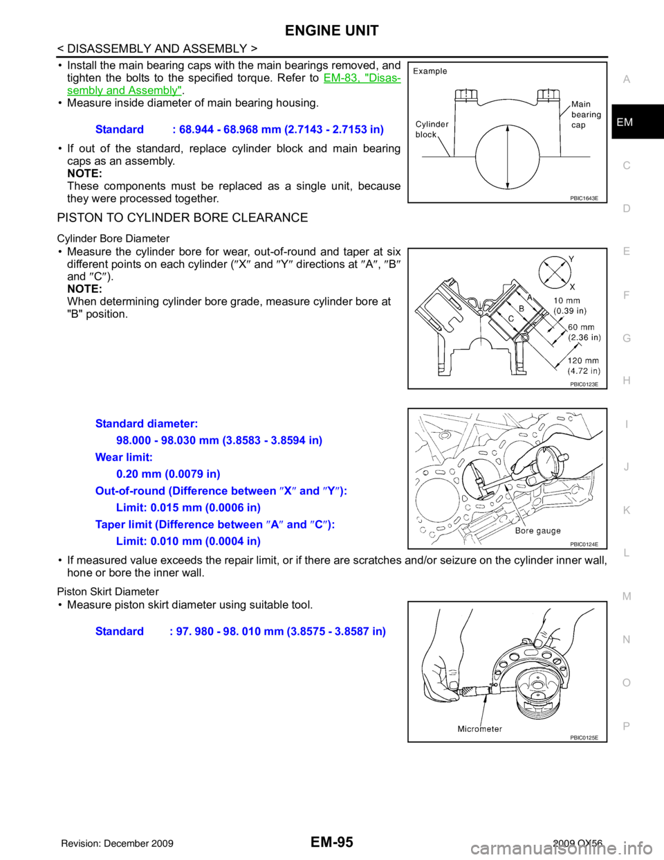
• Measure inside diameter of main bearing housing.
• If out of the standard, replace cylinder block and main bearing caps as an assembly.
NOTE:
These components must be replaced as a single unit, because
they were processed together.
PISTON TO CYLINDER BORE CLEARANCE
Cylinder Bore Diameter
• Measure the cylinder bore for wear, out-of-round and taper at six
different points on each cylinder ( ″X″ and ″Y″ directions at ″A″ , ″B″
and ″C ″).
NOTE:
When determining cylinder bore grade, measure cylinder bore at
"B" position.
• If measured value exceeds the repair limit, or if ther e are scratches and/or seizure on the cylinder inner wall,
hone or bore the inner wall.
Piston Skirt Diameter
• Measure piston skirt diameter using suitable tool. Standard : 68.944 - 68.968 mm (2.7143 - 2.7153 in)
PBIC1643E
PBIC0123E
Standard diameter:
98.000 - 98.030 mm (3.8583 - 3.8594 in)
Wear limit: 0.20 mm (0.0079 in)
Out-of-round (Difference between ″X″ and ″Y″ ):
Limit: 0.015 mm (0.0006 in)
Taper limit (Difference between ″A ″ and ″C ″):
Limit: 0.010 mm (0.0004 in)
PBIC0124E
Standard : 97. 980 - 98. 010 mm (3.8575 - 3.8587 in)
PBIC0125E
Revision: December 20092009 QX56
Page 1920 of 4171
ENGINE UNITEM-97
< DISASSEMBLY AND ASSEMBLY >
C
DE
F
G H
I
J
K L
M A
EM
NP
O
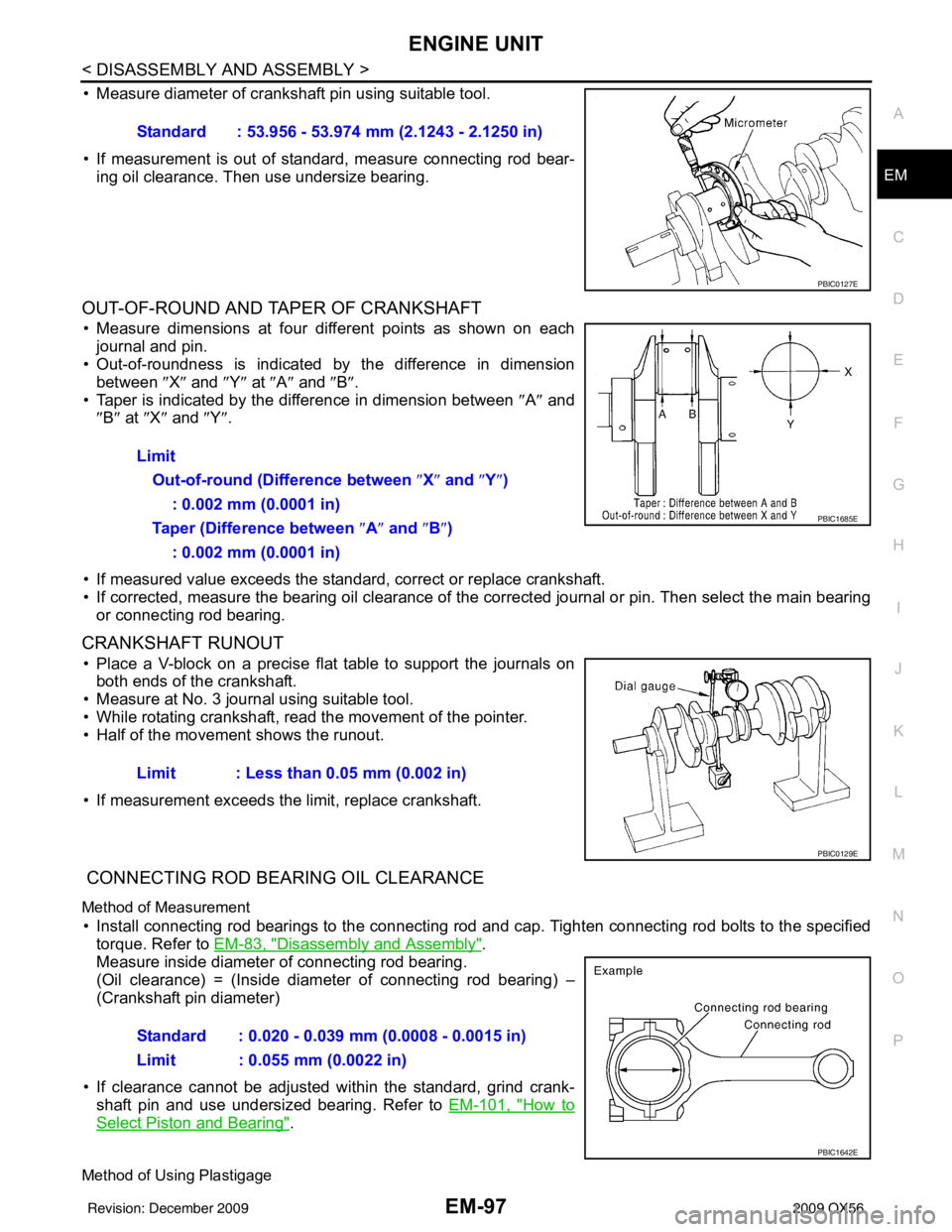
• Measure diameter of crankshaft pin using suitable tool.
• If measurement is out of standard, measure connecting rod bear-
ing oil clearance. Then use undersize bearing.
OUT-OF-ROUND AND TAPER OF CRANKSHAFT
• Measure dimensions at four di fferent points as shown on each
journal and pin.
• Out-of-roundness is indicated by the difference in dimension
between ″X″ and ″Y″ at ″A″ and ″B″ .
• Taper is indicated by the difference in dimension between ″A ″ and
″ B″ at ″X ″ and ″Y″ .
• If measured value exceeds the standard, correct or replace crankshaft.
• If corrected, measure the bearing oil clearance of the corrected journal or pin. Then select the main bearing or connecting rod bearing.
CRANKSHAFT RUNOUT
• Place a V-block on a precise flat table to support the journals onboth ends of the crankshaft.
• Measure at No. 3 journal using suitable tool.
• While rotating crankshaft, read the movement of the pointer.
• Half of the movement shows the runout.
• If measurement exceeds the limit, replace crankshaft.
CONNECTING ROD BEARING OIL CLEARANCE
Method of Measurement
• Install connecting rod bearings to the connecting rod and cap. Tighten connecting rod bolts to the specified
torque. Refer to EM-83, "
Disassembly and Assembly".
Measure inside diameter of connecting rod bearing.
(Oil clearance) = (Inside diameter of connecting rod bearing) –
(Crankshaft pin diameter)
• If clearance cannot be adjusted wit hin the standard, grind crank-
shaft pin and use undersized bearing. Refer to EM-101, "
How to
Select Piston and Bearing".
Method of Using Plastigage
Standard : 53.956 - 53.974 mm (2.1243 - 2.1250 in)
PBIC0127E
Limit
Out-of-round (Difference between ″X ″ and ″ Y″)
: 0.002 mm (0.0001 in)
Taper (Difference between ″ A″ and ″B ″)
: 0.002 mm (0.0001 in)
PBIC1685E
Limit : Less than 0.05 mm (0.002 in)
PBIC0129E
Standard : 0.020 - 0.039 mm (0.0008 - 0.0015 in)
Limit : 0.055 mm (0.0022 in)
PBIC1642E
Revision: December 20092009 QX56
Page 1921 of 4171
EM-98
< DISASSEMBLY AND ASSEMBLY >
ENGINE UNIT
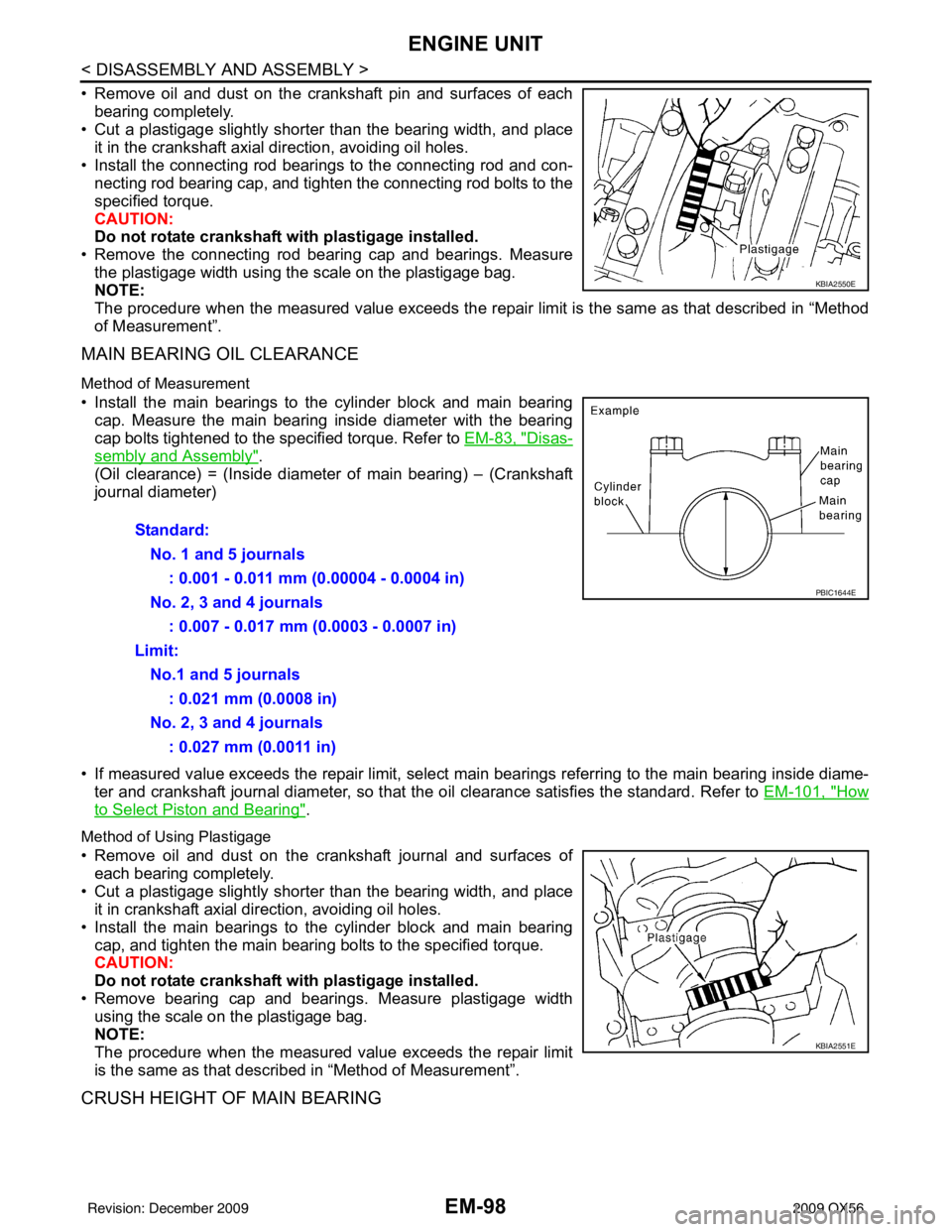
• Remove oil and dust on the crankshaft pin and surfaces of eachbearing completely.
• Cut a plastigage slightly shorter than the bearing width, and place
it in the crankshaft axial direction, avoiding oil holes.
• Install the connecting rod beari ngs to the connecting rod and con-
necting rod bearing cap, and tighten the connecting rod bolts to the
specified torque.
CAUTION:
Do not rotate crankshaft with plastigage installed.
• Remove the connecting rod bear ing cap and bearings. Measure
the plastigage width using the scale on the plastigage bag.
NOTE:
The procedure when the measured value exceeds the repair limit is the same as that described in “Method
of Measurement”.
MAIN BEARING OIL CLEARANCE
Method of Measurement
• Install the main bearings to the cylinder block and main bearing cap. Measure the main bearing inside diameter with the bearing
cap bolts tightened to the specified torque. Refer to EM-83, "
Disas-
sembly and Assembly".
(Oil clearance) = (Inside diameter of main bearing) – (Crankshaft
journal diameter)
• If measured value exceeds the repair limit, select main bearings referring to the main bearing inside diame-
ter and crankshaft journal diameter, so that the oil clearance satisfies the standard. Refer to EM-101, "
How
to Select Piston and Bearing".
Method of Using Plastigage
• Remove oil and dust on the crankshaft journal and surfaces of
each bearing completely.
• Cut a plastigage slightly shorter than the bearing width, and place it in crankshaft axial direction, avoiding oil holes.
• Install the main bearings to the cylinder block and main bearing cap, and tighten the main bearing bolts to the specified torque.
CAUTION:
Do not rotate crankshaft with plastigage installed.
• Remove bearing cap and bearings. Measure plastigage width using the scale on the plastigage bag.
NOTE:
The procedure when the measured value exceeds the repair limit
is the same as that descri bed in “Method of Measurement”.
CRUSH HEIGHT OF MAIN BEARING
KBIA2550E
Standard:
No. 1 and 5 journals : 0.001 - 0.011 mm (0.00004 - 0.0004 in)
No. 2, 3 and 4 journals : 0.007 - 0.017 mm (0.0003 - 0.0007 in)
Limit: No.1 and 5 journals : 0.021 mm (0.0008 in)
No. 2, 3 and 4 journals : 0.027 mm (0.0011 in)
PBIC1644E
KBIA2551E
Revision: December 20092009 QX56
Page 1924 of 4171
HOW TO SELECT PISTON AND BEARINGEM-101
< DISASSEMBLY AND ASSEMBLY >
C
DE
F
G H
I
J
K L
M A
EM
NP
O
HOW TO SELECT PISTON AND BEARING
How to Select Piston and BearingINFOID:0000000005885904
DESCRIPTION
*For the service parts, the grade for fitting cannot be selected between a piston pin and a connecting rod.
(Only 0 grade is available.) The information at the sh
ipment from the plant is described as a reference.
• The identification grade stamped on each part is the grade for the dimension measured in new condition.
This grade cannot apply to reused parts.
• For reused or repaired parts, measure the dimens ion accurately. Determine the grade by comparing the
measurement with the values of each selection table.
• For details of the measurement method of each part , the reuse standards, and the selection method of the
selective fitting parts, follow the applicable procedures.
HOW TO SELECT PISTON
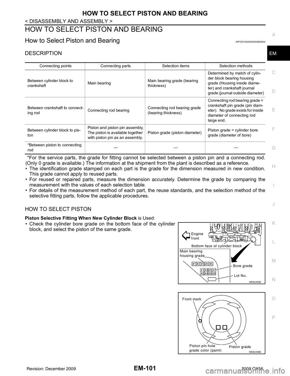
Piston Selective Fitting When New Cylinder Block is Used:
• Check the cylinder bore grade on the bottom face of the cylinder
block, and select the piston of the same grade.
Connecting points Connecting parts Selection itemsSelection methods
Between cylinder block to
crankshaft Main bearing Main bearing grade (bearing
thickness)Determined by match of cylin-
der block bearing housing
grade (Housing inside diame-
ter) and crankshaft journal
grade (journal outside diameter)
Between crankshaft to connect-
ing rod Connecting rod bearing Connecting rod bearing grade
(bearing thickness)Connecting rod bearing grade =
crankshaft pin grade (pin diam-
eter). No grade exists for inside
diameter of connecting rod
large end.
Between cylinder block to pis-
ton Piston and piston pin assembly.
The piston is available together
with piston pin as an assembly.
Piston grade (piston diameter)
Piston grade = cylinder bore
grade (diameter of bore)
*Between piston to connecting
rod ———
KBIA2495E
KBIA2496E
Revision: December 20092009 QX56
Page 1925 of 4171
EM-102
< DISASSEMBLY AND ASSEMBLY >
HOW TO SELECT PISTON AND BEARING
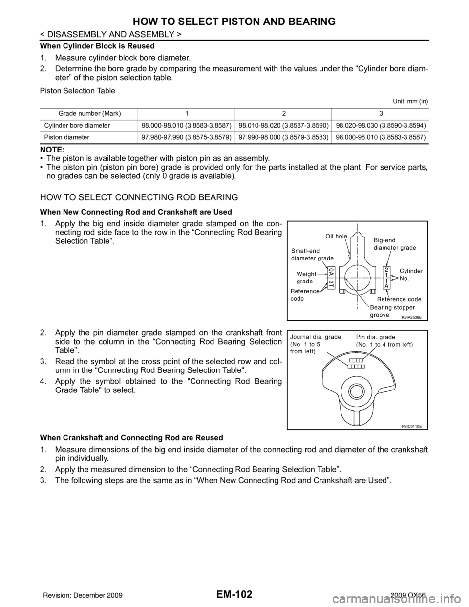
When Cylinder Block is Reused
1. Measure cylinder block bore diameter.
2. Determine the bore grade by comparing the measurement with the values under the “Cylinder bore diam-
eter” of the piston selection table.
Piston Selection Table
Unit: mm (in)
NOTE:
• The piston is available together with piston pin as an assembly.
• The piston pin (piston pin bore) grade is provided only for the parts installed at the plant. For service parts, no grades can be selected (only 0 grade is available).
HOW TO SELECT CONNECTING ROD BEARING
When New Connecting Rod and Crankshaft are Used
1. Apply the big end inside diameter grade stamped on the con-
necting rod side face to the row in the “Connecting Rod Bearing
Selection Table”.
2. Apply the pin diameter grade stamped on the crankshaft front side to the column in the “Connecting Rod Bearing Selection
Table”.
3. Read the symbol at the cross point of the selected row and col-
umn in the “Connecting Rod Bearing Selection Table".
4. Apply the symbol obtained to the "Connecting Rod Bearing Grade Table" to select.
When Crankshaft and Connecting Rod are Reused
1. Measure dimensions of the big end inside diameter of the connecting rod and diameter of the crankshaftpin individually.
2. Apply the measured dimension to the “Connecting Rod Bearing Selection Table”.
3. The following steps are the same as in “When New Connecting Rod and Crankshaft are Used”.
Grade number (Mark) 12 3
Cylinder bore diameter 98.000-98.010 (3.8583-3.8587) 98.010-98.020 (3.8587-3.8590) 98.020-98.030 (3.8590-3.8594)
Piston diameter 97.980-97.990 (3.8575-3.8579) 97.990-98.000 (3.8579-3.8583) 98.000-98.010 (3.8583-3.8587)
KBIA2536E
PBIC0110E
Revision: December 20092009 QX56
Page 1926 of 4171
HOW TO SELECT PISTON AND BEARINGEM-103
< DISASSEMBLY AND ASSEMBLY >
C
DE
F
G H
I
J
K L
M A
EM
NP
O
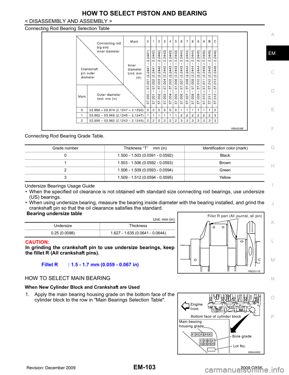
Connecting Rod Bearing Selection Table
Connecting Rod Bearing Grade Table.
Undersize Bearings Usage Guide
• When the specified oil clearance is not obtained with standard size connecting rod bearings, use undersize
(US) bearings.
• When using undersize bearing, measure the bearing inside diameter with the bearing installed, and grind the
crankshaft pin so that the oil clearance satisfies the standard.
Bearing undersize table
Unit: mm (in)
CAUTION:
In grinding the crankshaft pin to use undersize bearings, keep
the fillet R (All crankshaft pins).
HOW TO SELECT MAIN BEARING
When New Cylinder Block and Crankshaft are Used
1. Apply the main bearing housing grade on the bottom face of the cylinder block to the row in "Main Bearings Selection Table".
KBIA2538E
Grade number Thickness “T” mm (in) Identification color (mark)
0 1.500 - 1.503 (0.0591 - 0.0592) Black
1 1.503 - 1.506 (0.0592 - 0.0593) Brown
2 1.506 - 1.509 (0.0593 - 0.0594) Green
3 1.509 - 1.512 (0.0594 - 0.0595) Yellow
UndersizeThickness
0.25 (0.0098) 1.627 - 1.635 (0.0641 - 0.0644)
Fillet R : 1.5 - 1.7 mm (0.059 - 0.067 in)
PBIC0111E
KBIA2495E
Revision: December 20092009 QX56
Page 1927 of 4171
EM-104
< DISASSEMBLY AND ASSEMBLY >
HOW TO SELECT PISTON AND BEARING
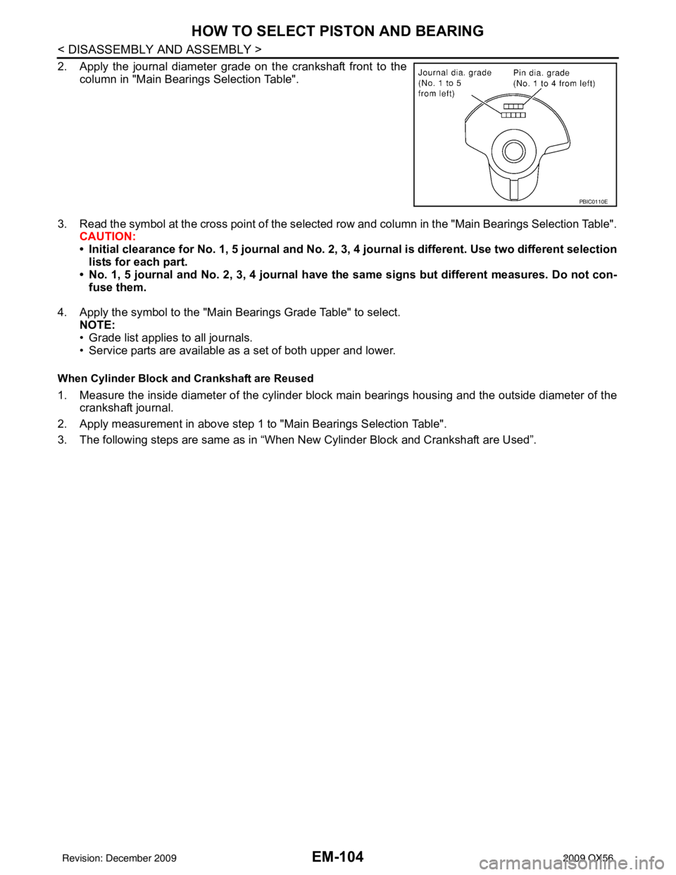
2. Apply the journal diameter grade on the crankshaft front to thecolumn in "Main Bearings Selection Table".
3. Read the symbol at the cross point of the selected row and column in the "Main Bearings Selection Table".
CAUTION:
• Initial clearance for No. 1, 5 journal and No. 2, 3, 4 journal is different. Use two different selection
lists for each part.
• No. 1, 5 journal and No. 2, 3, 4 journal have the same signs but different measures. Do not con-
fuse them.
4. Apply the symbol to the "Main Bearings Grade Table" to select. NOTE:
• Grade list applies to all journals.
• Service parts are available as a set of both upper and lower.
When Cylinder Block and Crankshaft are Reused
1. Measure the inside diameter of the cylinder block main bearings housing and the outside diameter of the
crankshaft journal.
2. Apply measurement in above step 1 to "Main Bearings Selection Table".
3. The following steps are same as in “When New Cylinder Block and Crankshaft are Used”.
PBIC0110E
Revision: December 20092009 QX56