Page 2091 of 4171
ADJUSTMENT AND INSPECTIONEXL-143
< ON-VEHICLE REPAIR >
C
DE
F
G H
I
J
K
M A
B
EXL
N
O P
ON-VEHICLE REPAIR
ADJUSTMENT AND INSPECTION
HEADLAMP
HEADLAMP : Aiming AdjustmentINFOID:0000000003776220
NOTE:
• For details, refer to the regulations in your area.
• If vehicle front body has been repaired and /or the headlamp assembly has been replaced, check headlamp
aiming.
HEADLAMP AIMING
NOTE:
• Before performing aiming adjustment, check the following:
- Ensure all tires are inflated to correct pressure.
- Place vehicle and screen on level surface.
- Ensure there is no load in vehicle other than the driver (or equivalent weight placed in driver's position). Coolant and engine oil filled to correct level, and fuel tank full.
- Confirm spare tire, jack and tools are properly stowed.
- Aim each headlamp individually and ensure other headlamp beam pattern is blocked from screen.
- Use adjusting screw to perform aiming adjustment
WKIA1859E
Revision: December 20092009 QX56
Page 2093 of 4171
ADJUSTMENT AND INSPECTIONEXL-145
< ON-VEHICLE REPAIR >
C
DE
F
G H
I
J
K
M A
B
EXL
N
O P
• See that vehicle is unloaded (except for full levels of coolant, engine oil and fuel, and spare tire, jack, and tools). Have the driver
or equivalent weight placed in driver seat.
Adjust aiming in the vertical direction by turning the adjustment
screw.
NOTE:
Access adjustment screw from underneath front bumper. Turn screw
clockwise to raise pattern and c ounterclockwise to lower pattern.
1. Set the distance between the screen and the center of the fog lamp lens as shown.
2. Turn front fog lamps ON.
3. Adjust front fog lamps using adjusting screw so that the top edge of the high intensity zone is 200 mm (7.9 in) below the height of
the fog lamp centers as shown.
• When performing adjustment, if necessary, cover the head-lamps and opposite fog lamp.
SEL350X
MEL327G
MEL328GA
Revision: December 20092009 QX56
Page 2215 of 4171
IDENTIFICATION INFORMATIONGI-21
< FEATURES OF NEW MODEL >
C
DE
F
G H
I
J
K L
M B
GI
N
O P
Identification NumberINFOID:0000000003771190
VEHICLE IDENTIFICATION NUMBER ARRANGEMENT
1. Emission control information label 2. F.M.V.S.S./C.M.V.S.S. certification label 3. Tire placard
4. Vehicle identification number plate 5. Air conditioning specfication label
AWAIA0026GB
Position Character Qualifier Definition
1 5N1 Manufacturer 5N1: USA produced multi-purpose vehicle
2
3
4 A Engine type A: VK56DE
5 A0 Vehicle line A0: Infiniti QX56
6
7 8 Body type 8: 4 door wagon
8C Gross vehicle
weight ratingC: 4WD, 4-wheel ABS, Class F
D: 2WD, 4-wheel ABS, Class F
9 * Check digit (0 to 9 or X) The code for the check digit is determined by a mathematical com-
putation.
10 9 Model year 2009
11 NManufacturing
plant
N: Canton Mississippi
12
XXXXXX Vehicle serial num-
ber Chassis number
13
14
15
16
17
Revision: December 20092009 QX56
Page 2219 of 4171

PRECAUTIONSGI-25
< PRECAUTION >
C
DE
F
G H
I
J
K L
M B
GI
N
O P
2. Use the Intelligent Key or mechanical key to turn the ignition switch to the ″ACC ″ position. At this time, the
steering lock will be released.
3. Disconnect both battery cables. The steering lock will remain released and the steering wheel can be
rotated.
4. Perform the necessary repair operation.
5. When the repair work is completed, return the ignition switch to the ″LOCK ″ position before connecting
the battery cables. (At this time, the steering lock mechanism will engage.)
6. Perform a self-diagnosis check of al l control units using CONSULT-III.
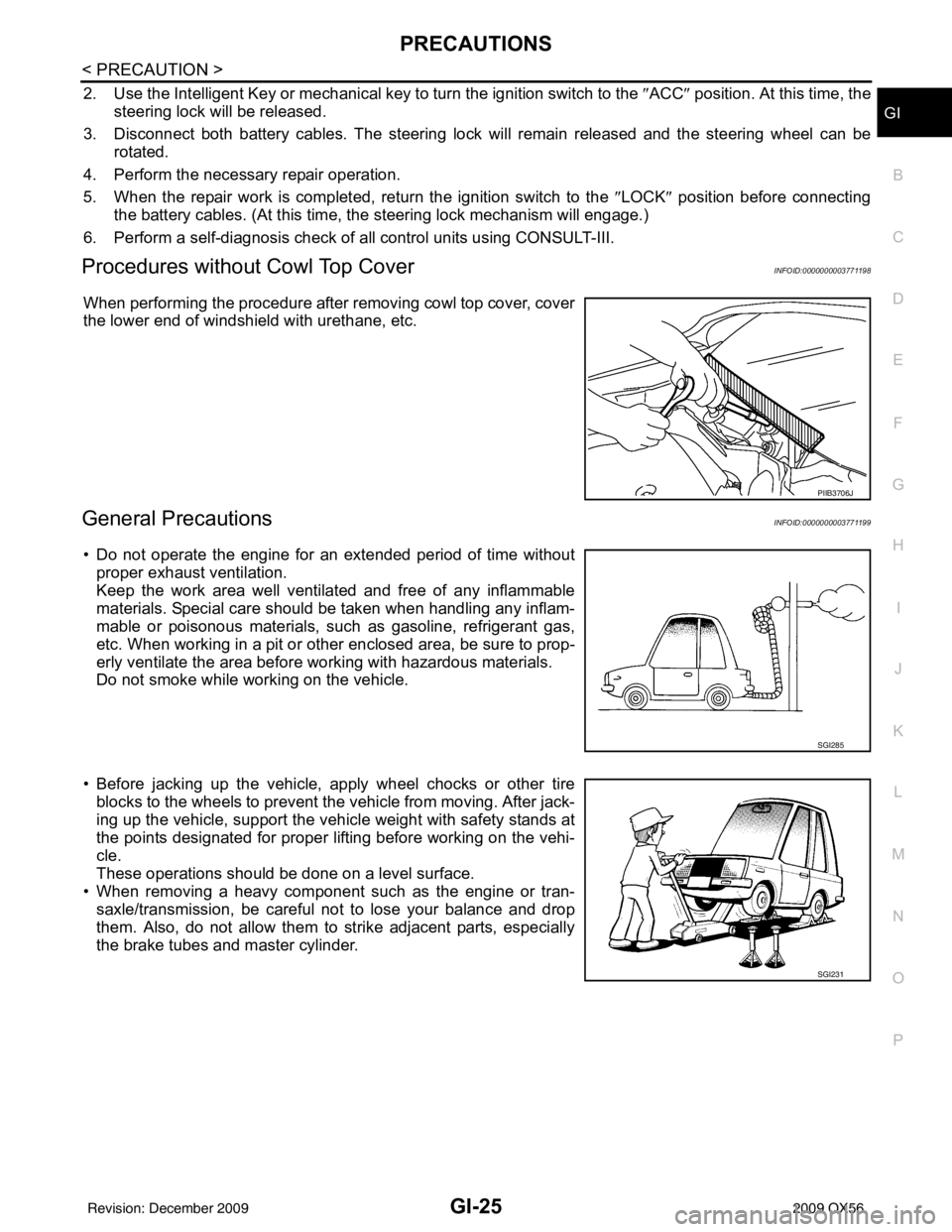
Procedures without Cowl Top CoverINFOID:0000000003771198
When performing the procedure after removing cowl top cover, cover
the lower end of windshield with urethane, etc.
General PrecautionsINFOID:0000000003771199
• Do not operate the engine for an extended period of time without
proper exhaust ventilation.
Keep the work area well ventilated and free of any inflammable
materials. Special care should be taken when handling any inflam-
mable or poisonous materials, such as gasoline, refrigerant gas,
etc. When working in a pit or ot her enclosed area, be sure to prop-
erly ventilate the area before working with hazardous materials.
Do not smoke while working on the vehicle.
• Before jacking up the vehicle, apply wheel chocks or other tire blocks to the wheels to prevent t he vehicle from moving. After jack-
ing up the vehicle, support the vehicle weight with safety stands at
the points designated for proper lifting before working on the vehi-
cle.
These operations should be done on a level surface.
• When removing a heavy component such as the engine or tran-
saxle/transmission, be careful not to lose your balance and drop
them. Also, do not allow them to strike adjacent parts, especially
the brake tubes and master cylinder.
PIIB3706J
SGI285
SGI231
Revision: December 20092009 QX56
Page 2276 of 4171
HA-12
< PRECAUTION >
PRECAUTIONS
Never attempt to connect HFC-134a (R-134a) service couplers to a
CFC-12 (R-12) A/C system. The HFC-134a (R-134a) couplers will
not properly connect to the CFC-12 (R-12) system. If an improper
connection is attempted, discharging and contamination may occur.
REFRIGERANT WEIGHT SCALE
Verify that no refrigerant other than HFC134a (R-134a) and specified
oils have been used with the scale. If the scale controls refrigerant
flow electronically, the hose fitting must be 1/2”-16 ACME.
CHARGING CYLINDER
Using a charging cylinder is not recommended. Refrigerant may be vented into air from cylinder's top valve
when filling the cylinder with refrigerant. Also, the accu racy of the cylinder is generally less than that of an
electronic scale or of quality recycle/recharge equipment.
Shut-off valve rotati on A/C service valve
Clockwise Open
Counterclockwise Close
RHA273D
RHA274D
Revision: December 20092009 QX56
Page 2280 of 4171
HA-16
< PREPARATION >
PREPARATION
Commercial Service Tool
INFOID:0000000003775297
—
(J-39699)
Refrigerant weight scale For measuring of refrigerant
Fitting size-Thread size
1/2”-16 ACME
—
(J-39649)
Vacuum pump
(Including the isolator valve) Capacity:
Air displacement: 4 CFM
Micron rating: 20 microns
Oil capacity: 482 g (17 oz)
Fitting size-Thread size
1/2”-16 ACME
Tool number
(Kent-Moore No.)
Tool name
Description
S-NT200
S-NT203
Tool name
Description
(J-41810-NI)
Refrigerant identifier equipment (R-
134a) For checking refrigerant purity and
system contamination
Power tool Loosening bolts, screws and nuts
RJIA0197E
PIIB1407E
Revision: December 20092009 QX56
Page 2285 of 4171
REFRIGERATION SYSTEMHA-21
< ON-VEHICLE MAINTENANCE >
C
DE
F
G H
J
K L
M A
B
HA
N
O P
1. Shut-off valve 2. A/C service valve 3. Recovery/recycling equipment
4. Refrigerant container (HFC-134a) 5. Weight scale (J-39650) 6. Evacuating vacuum pump (J-39699)
7. Manifold gauge set (J-39183)
*1 HA-22, "Maintenance of Oil Quantity
in Compressor"
*3HAC-113, "Performance Chart"*5 HA-4, "Contaminated Refrigerant"
*2HAC-110, "Component Function
Check"
*4HAC-111, "Diagnostic Work Flow"
WJIA1923E
Revision: December 20092009 QX56
Page 2672 of 4171

OIL PUMPLU-17
< DISASSEMBLY AND ASSEMBLY >
C
DE
F
G H
I
J
K L
M A
LU
NP
O
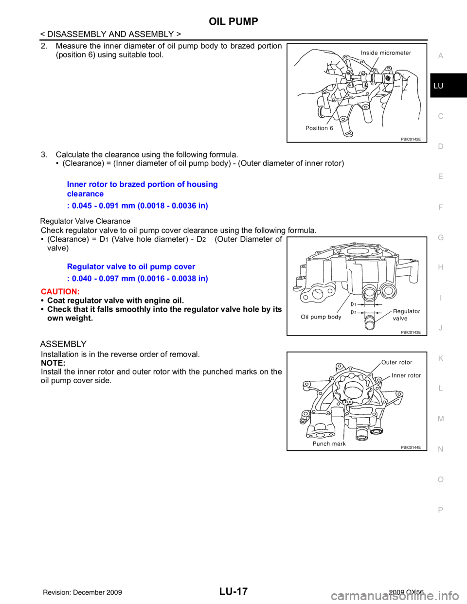
2. Measure the inner diameter of oil pump body to brazed portion
(position 6) using suitable tool.
3. Calculate the clearance using the following formula. • (Clearance) = (Inner diameter of oil pump body) - (Outer diameter of inner rotor)
Regulator Valve Clearance
Check regulator valve to oil pump cover clearance using the following formula.
• (Clearance) = D
1 (Valve hole diameter) - D2 (Outer Diameter of
valve)
CAUTION:
• Coat regulator valve with engine oil.
• Check that it falls smoothly into the regulator valve hole by its
own weight.
ASSEMBLY
Installation is in the reverse order of removal.
NOTE:
Install the inner rotor and outer rotor with the punched marks on the
oil pump cover side.
PBIC0142E
Inner rotor to brazed portion of housing
clearance
: 0.045 - 0.091 mm (0.0018 - 0.0036 in)
Regulator valve to oil pump cover
: 0.040 - 0.097 mm (0.0016 - 0.0038 in)
PBIC0143E
PBIC0144E
Revision: December 20092009 QX56