2009 INFINITI QX56 ECO mode
[x] Cancel search: ECO modePage 2693 of 4171

MA-20
< ON-VEHICLE MAINTENANCE >
ENGINE MAINTENANCE
REMOVAL
1. Disconnect the harness connector from the ignition coil.
2. Remove ignition coil.CAUTION:
Do not shock ig nition coil.
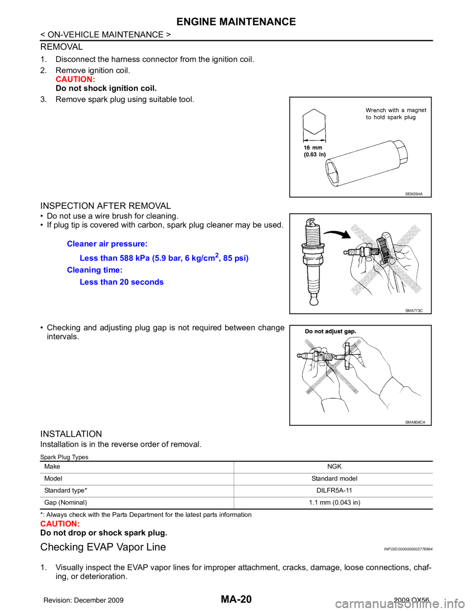
3. Remove spark plug using suitable tool.
INSPECTION AFTER REMOVAL
• Do not use a wire brush for cleaning.
• If plug tip is covered with carbon, spark plug cleaner may be used.
• Checking and adjusting plug gap is not required between change intervals.
INSTALLATION
Installation is in the reverse order of removal.
Spark Plug Types
*: Always check with the Parts Department for the latest parts information
CAUTION:
Do not drop or shock spark plug.
Checking EVAP Vapor LineINFOID:0000000003776994
1. Visually inspect the EVAP vapor lines for improper attachment, cracks, damage, loose connections, chaf-
ing, or deterioration.
SEM294A
Cleaner air pressure:
Less than 588 kPa (5.9 bar, 6 kg/cm
2, 85 psi)
Cleaning time: Less than 20 seconds
SMA773C
SMA806CA
Make NGK
Model Standard model
Standard type* DILFR5A-11
Gap (Nominal) 1.1 mm (0.043 in)
Revision: December 20092009 QX56
Page 2715 of 4171

MIR-8
< PRECAUTION >
PRECAUTIONS
PRECAUTION
PRECAUTIONS
Precaution for Supplemental Restraint System (SRS) "AIR BAG" and "SEAT BELT
PRE-TENSIONER"
INFOID:0000000005867736
The Supplemental Restraint System such as “A IR BAG” and “SEAT BELT PRE-TENSIONER”, used along
with a front seat belt, helps to reduce the risk or severity of injury to the driver and front passenger for certain
types of collision. This system includes seat belt switch inputs and dual stage front air bag modules. The SRS
system uses the seat belt switches to determine the front air bag deployment, and may only deploy one front
air bag, depending on the severity of a collision and w hether the front occupants are belted or unbelted.
Information necessary to service the system safely is included in the SR and SB section of this Service Man-
ual.
WARNING:
• To avoid rendering the SRS inopera tive, which could increase the risk of personal injury or death in
the event of a collision which would result in air bag inflation, all maintenance must be performed by
an authorized NISSAN/INFINITI dealer.
• Improper maintenance, including in correct removal and installation of the SRS, can lead to personal
injury caused by unintent ional activation of the system. For re moval of Spiral Cable and Air Bag
Module, see the SR section.
• Do not use electrical test equipmen t on any circuit related to the SRS unless instructed to in this
Service Manual. SRS wiring harn esses can be identified by yellow and/or orange harnesses or har-
ness connectors.
PRECAUTIONS WHEN USING POWER TOOLS (AIR OR ELECTRIC) AND HAMMERS
WARNING:
• When working near the Airbag Diagnosis Sensor Unit or other Airbag System sensors with the Igni-
tion ON or engine running, DO NOT use air or electri c power tools or strike near the sensor(s) with a
hammer. Heavy vibration could activate the sensor( s) and deploy the air bag(s), possibly causing
serious injury.
• When using air or electric power tools or hammers , always switch the Ignition OFF, disconnect the
battery, and wait at least 3 minu tes before performing any service.
Precaution Necessary for Steering W heel Rotation After Battery Disconnect
INFOID:0000000005867737
NOTE:
• This Procedure is applied only to models with Intelligent Key system and NATS (NISSAN ANTI-THEFT SYS-
TEM).
• Remove and install all control units after disconnecting both battery cables with the ignition knob in the
″LOCK ″ position.
• Always use CONSULT-III to perform self-diagnosis as a part of each function inspection after finishing work.
If DTC is detected, perform trouble diagnosis according to self-diagnostic results.
For models equipped with the Intelligent Key system and NATS, an electrically controlled steering lock mech-
anism is adopted on the key cylinder.
For this reason, if the battery is disconnected or if the battery is discharged, the steering wheel will lock and
steering wheel rotation will become impossible.
If steering wheel rotation is required when battery pow er is interrupted, follow the procedure below before
starting the repair operation.
OPERATION PROCEDURE
1. Connect both battery cables. NOTE:
Supply power using jumper cables if battery is discharged.
2. Use the Intelligent Key or mechanical key to turn the ignition switch to the ″ACC ″ position. At this time, the
steering lock will be released.
3. Disconnect both battery cables. The steering lock will remain released and the steering wheel can be rotated.
4. Perform the necessary repair operation.
Revision: December 20092009 QX56
Page 2727 of 4171

MWI
METER SYSTEMMWI-5
< FUNCTION DIAGNOSIS >
C
DE
F
G H
I
J
K L
M B A
O P
FUNCTION DIAGNOSIS
METER SYSTEM
METER SYSTEM
METER SYSTEM : System DiagramINFOID:0000000003776580
METER SYSTEM : System DescriptionINFOID:0000000003776581
COMBINATION METER
• Speedometer, odo/trip meter, tachometer, fuel gauge, engine coolant temperature gauge, engine oil pres-
sure gauge, voltage gauge and information display are controlled by the unified meter control unit, which is
built into the combination meter.
• Warning and indicator lamps are controlled by the unified meter control unit and by components connected directly to the combination meter.
• Digital meter is adopted for odo/trip meter.* *The record of the odometer is kept even if the battery cable is disconnected. The record of the trip meter is
erased when the battery cable is disconnected.
• Odo/trip meter segments can be checked in diagnosis mode.
• Meter/gauge can be checked in diagnosis mode.
AWNIA0274GB
Revision: December 20092009 QX56
Page 2744 of 4171

MWI-22
< FUNCTION DIAGNOSIS >
COMPASS
COMPASS
Description (Early Production)INFOID:0000000004244472
DESCRIPTION
With the ignition switch in the ON position, and the mode (N) switch
ON, the compass display will indicate the direction the vehicle is
heading.
Vehicle direction is displayed as follows:
• N: north
• E: east
• S: south
•W: west
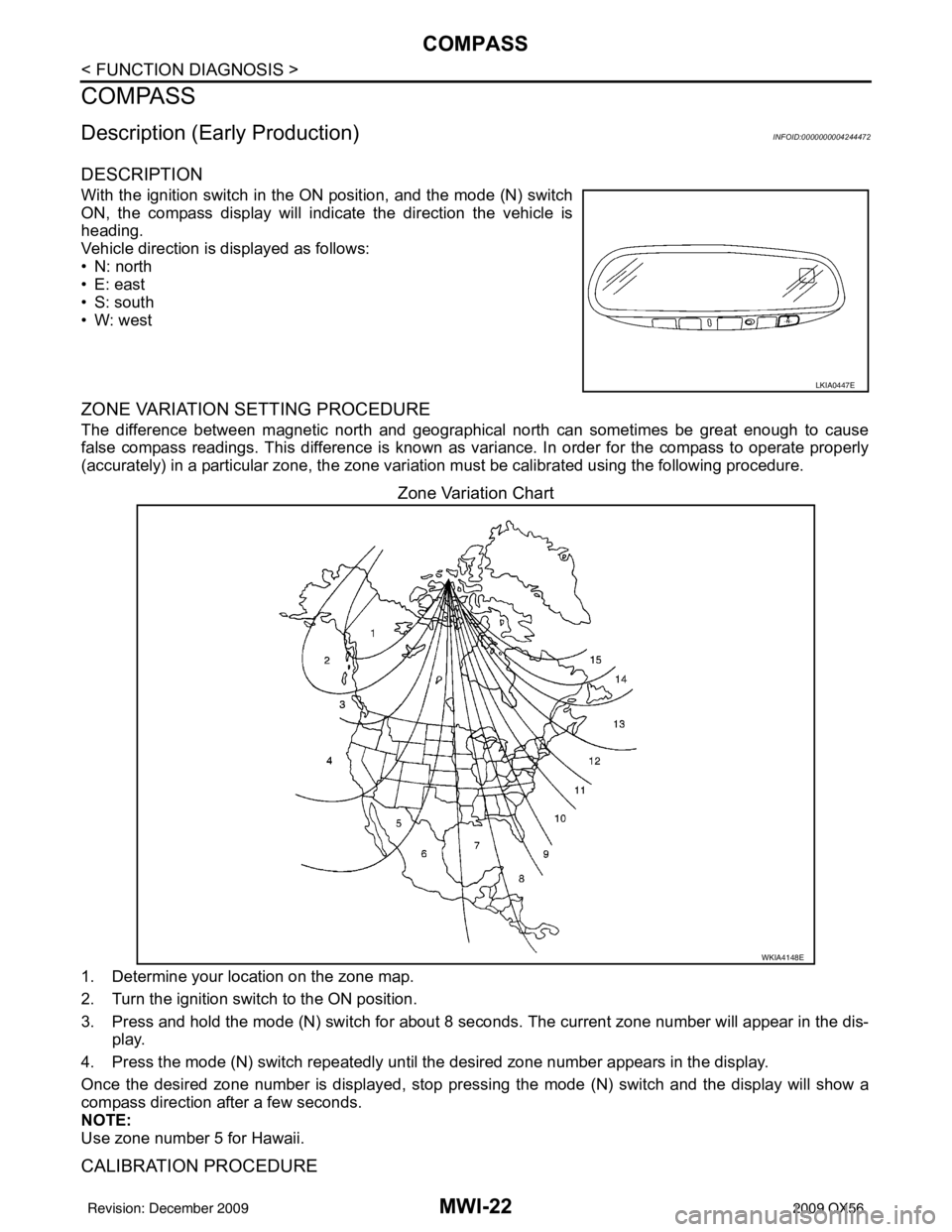
ZONE VARIATION SETTING PROCEDURE
The difference between magnetic north and geographical north can sometimes be great enough to cause
false compass readings. This difference is known as variance. In order for the compass to operate properly
(accurately) in a particular zone, the zone variation must be calibra ted using the following procedure.
Zone Variation Chart
1. Determine your location on the zone map.
2. Turn the ignition switch to the ON position.
3. Press and hold the mode (N) switch for about 8 sec onds. The current zone number will appear in the dis-
play.
4. Press the mode (N) switch repeatedly until the desired zone number appears in the display.
Once the desired zone number is displayed, stop pre ssing the mode (N) switch and the display will show a
compass direction after a few seconds.
NOTE:
Use zone number 5 for Hawaii.
CALIBRATION PROCEDURE
LKIA0447E
WKIA4148E
Revision: December 20092009 QX56
Page 2745 of 4171

MWI
COMPASSMWI-23
< FUNCTION DIAGNOSIS >
C
DE
F
G H
I
J
K L
M B A
O P
The compass display is equipped with an automatic correc tion function. If the compass display reads “CAL” or
the direction is not shown correctly, perform the correction procedure below.
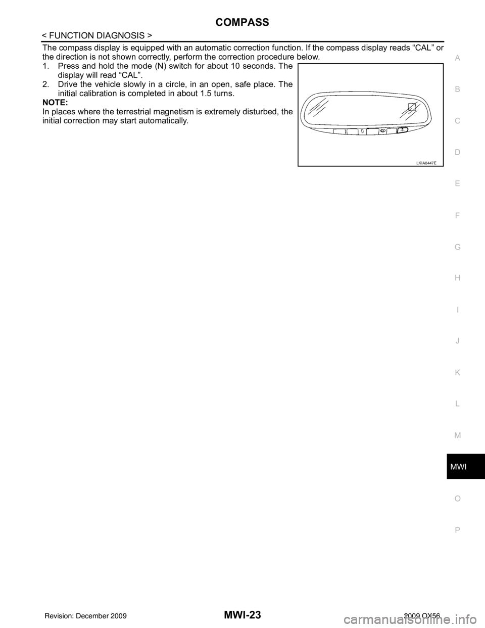
1. Press and hold the mode (N) switch for about 10 seconds. The display will read “CAL”.
2. Drive the vehicle slowly in a circle, in an open, safe place. The initial calibration is completed in about 1.5 turns.
NOTE:
In places where the terrestrial m agnetism is extremely disturbed, the
initial correction may start automatically.
LKIA0447E
Revision: December 20092009 QX56
Page 2746 of 4171

MWI-24
< FUNCTION DIAGNOSIS >
DIAGNOSIS SYSTEM (METER)
DIAGNOSIS SYSTEM (METER)
Diagnosis DescriptionINFOID:0000000003776626
SELF-DIAGNOSIS MODE
The following items can be checked during Combination Meter Self-Diagnosis Mode.
• Gauge sweep and present gauge values.
• Illuminates all odometer/trip meters and A/T indicator segments.
• Illuminates all micro controlled lamps/LEDs regardless of switch position.
• Displays estimated present battery voltage.
• Displays seat belt buckle switch LH status.
OPERATION PROCEDURE
NOTE:
• Once entered, combination meter self-diagnosis mode will function with the ignition switch in ON or START.
Combination meter self-diagnosis mode will exit upon turning the ignition switch to OFF or ACC.
• If the diagnosis function is activated with trip A displa yed, the mileage on trip A is reset to 0000.0. (Trip B
operates the same way.)
To initiate combination meter self-diagnosis mode, refer to the following procedure.
1. Turn the ignition switch ON, while pressing the odometer/trip meter switch for 5 - 8 \
seconds. When the diagnosis function is activated, the odometer/trip meter will display tESt.
NOTE:
Check combination meter power supply and ground circuit when self-diagnosis mode of combination meter
does not start. Refer to MWI-30, "
COMBINATION METER : Diagnosis Procedure". Replace combination
meter if normal. Refer to MWI-102, "
Removal and Installation".
COMBINATION METER SELF-DIAGNOSIS MODE FUNCTIONS
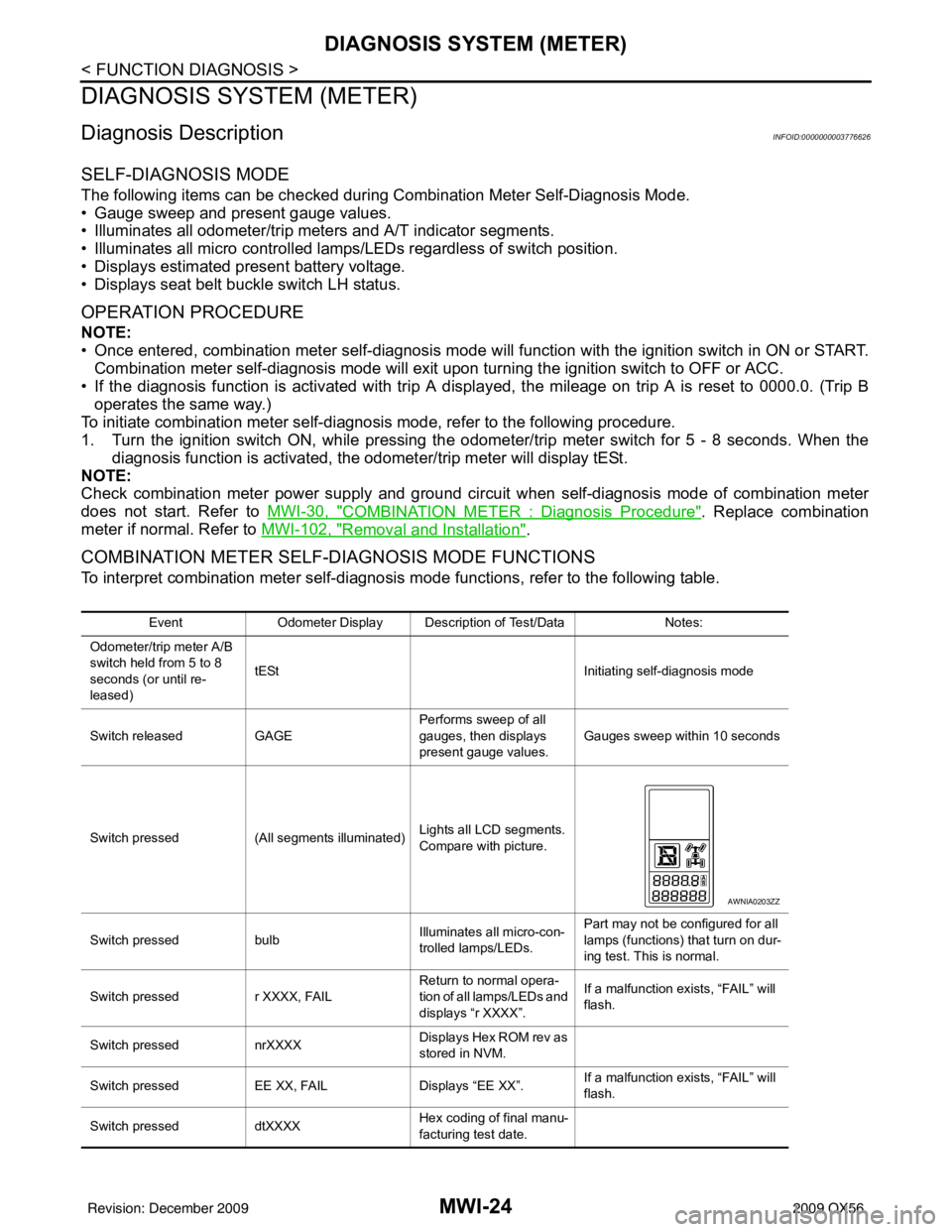
To interpret combination meter self-diagnosis mode functions, refer to the following table.
EventOdometer Display Description of Test/Data Notes:
Odometer/trip meter A/B
switch held from 5 to 8
seconds (or until re-
leased) tESt
Initiating self-diagnosis mode
Switch released GAGE Performs sweep of all
gauges, then displays
present gauge values.Gauges sweep within 10 seconds
Switch pressed (All segments illuminated) Lights all LCD segments.
Compare with picture.
Switch pressed bulbIlluminates all micro-con-
trolled lamps/LEDs. Part may not be configured for all
lamps (functions) th
at turn on dur-
ing test. This is normal.
Switch pressed r XXXX, FAIL Return to normal opera-
tion of all lamps/LEDs and
displays “r XXXX”.If a malfunction exists, “FAIL” will
flash.
Switch pressed nrXXXX Displays Hex ROM rev as
stored in NVM.
Switch pressed EE XX, FAIL Displays “EE XX”.If a malfunction exists, “FAIL” will
flash.
Switch pressed dtXXXX Hex coding of final manu-
facturing test date.
AWNIA0203ZZ
Revision: December 20092009 QX56
Page 2750 of 4171

MWI-28
< COMPONENT DIAGNOSIS >
DTC U1000 CAN COMMUNICATION
COMPONENT DIAGNOSIS
DTC U1000 CAN COMMUNICATION
DTC LogicINFOID:0000000003776628
DTC DETECTION LOGIC
Diagnosis ProcedureINFOID:0000000003776629
Symptom: Displays “CAN COMM CIRC [U1000]” as a self-diagnosis result of combination meter.
1.CHECK CAN COMMUNICATION
Select “SELF-DIAG RESULTS” mode for “METER/M&A” with CONSULT-III.
>> Go to “LAN system”. Refer to LAN-14, "
Trouble Diagnosis Flow Chart".
DTC CONSULT-III display Detection condition
U1000 CAN COMM CIRC
[U1000] When combination meter is not receiving CAN communication signals for 2 seconds or more.
Revision: December 20092009 QX56
Page 2784 of 4171

MWI-62
< ECU DIAGNOSIS >
COMBINATION METER
DTC Index
INFOID:0000000003776656
Function Specifications
Speedometer
Zero indication.
Tachometer
Fuel gauge
Engine coolant temperature gauge
Engine oil pressure gauge
Voltage gauge
A/T oil temperature gauge
Illumination control
Meter illumination Change to nighttime mode when communication is lost.
Segment LCD Odometer
Freeze current indication.
A/T position Display turns off.
Buzzer Buzzer turns off.
Warning lamp/indicator lamp ABS warning lamp
Lamp turns on when communication is lost.
Brake warning lamp
VDC OFF indicator lamp
SLIP indicator lamp
A/T CHECK warning lamp
Lamp turns off when communication is lost.
Oil pressure/coolant temperature
warning lamp
Light indicator
Malfunction indicator lamp
Master warning lamp
Air bag warning lamp
High beam indicator
Turn signal indicator lamp
CRUISE indicator lamp
Driver and passenger seat belt warn-
ing lamp
Lamp turns off when disconnected.
Charge warning lamp
Security indicator lamp
4WD indicator lamp
AT P i n d i c a t o r l a m p
CK SUSP warning lamp
Low tire pressure warning lamp
Lamp will flash every second for 1 minute and then stay on con-
tinuously thereafter.
CONSULT-III display
MalfunctionReference
page
CAN COMM CIRC
[U1000] Malfunction is detected in CAN communication.
CAUTION:
Even when there is no malfunction on CAN communication system, malfunction may be
misinterpreted when battery has low voltage (when maintaining 7 - 8 V for about 2 sec-
onds) or 10A fuse [No. 3, located in
the fuse block (J/B)] is disconnected. MWI-28
VEHICLE SPEED
CIRC
[B2205]Malfunction is detected when an erroneous speed signal is input.
CAUTION:
Even when there is no malfunction on speed signal system, malfunction may be misin-
terpreted when battery has lo
w voltage (when maintaining 7 - 8 V for about 2 seconds). MWI-29
Revision: December 20092009 QX56