2009 INFINITI QX56 warning
[x] Cancel search: warningPage 1909 of 4171
EM-86
< DISASSEMBLY AND ASSEMBLY >
ENGINE UNIT
ASSEMBLY
1. Fully air-blow the coolant and oil passages in the cylinder block, cylinder bore, and crankcase to removeany foreign material.
WARNING:
Use goggles to protect your eyes.
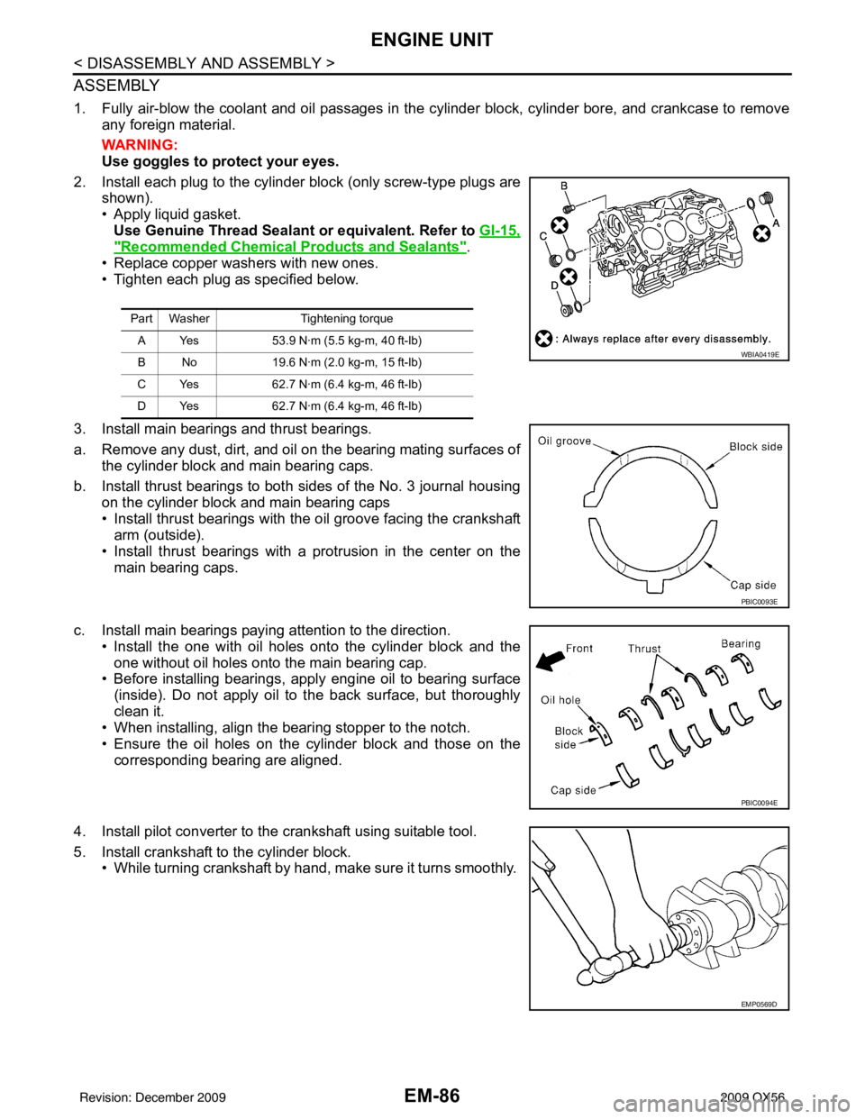
2. Install each plug to the cylinder block (only screw-type plugs are shown).
• Apply liquid gasket. Use Genuine Thread Sealant or equivalent. Refer to GI-15,
"Recommended Chemical Products and Sealants".
• Replace copper washers with new ones.
• Tighten each plug as specified below.
3. Install main bearings and thrust bearings.
a. Remove any dust, dirt, and oil on the bearing mating surfaces of the cylinder block and main bearing caps.
b. Install thrust bearings to both sides of the No. 3 journal housing on the cylinder block and main bearing caps
• Install thrust bearings with the oil groove facing the crankshaft
arm (outside).
• Install thrust bearings with a protrusion in the center on the
main bearing caps.
c. Install main bearings paying attention to the direction. • Install the one with oil holes onto the cylinder block and theone without oil holes onto the main bearing cap.
• Before installing bearings, apply engine oil to bearing surface
(inside). Do not apply oil to the back surface, but thoroughly
clean it.
• When installing, align the bearing stopper to the notch.
• Ensure the oil holes on the cylinder block and those on the
corresponding bearing are aligned.
4. Install pilot converter to the crankshaft using suitable tool.
5. Install crankshaft to the cylinder block. • While turning crankshaft by hand, make sure it turns smoothly.
Part Washer Tightening torque
A Yes 53.9 N·m (5.5 kg-m, 40 ft-lb)
B No 19.6 N·m (2.0 kg-m, 15 ft-lb)
C Yes 62.7 N·m (6.4 kg-m, 46 ft-lb)
D Yes 62.7 N·m (6.4 kg-m, 46 ft-lb)
WBIA0419E
PBIC0093E
PBIC0094E
EMP0569D
Revision: December 20092009 QX56
Page 1943 of 4171
EX-2
< PRECAUTION >
PRECAUTIONS
PRECAUTION
PRECAUTIONS
Precaution for Supplemental Restraint System (SRS) "AIR BAG" and "SEAT BELT
PRE-TENSIONER"
INFOID:0000000005851832
The Supplemental Restraint System such as “A IR BAG” and “SEAT BELT PRE-TENSIONER”, used along
with a front seat belt, helps to reduce the risk or severity of injury to the driver and front passenger for certain
types of collision. This system includes seat belt switch inputs and dual stage front air bag modules. The SRS
system uses the seat belt switches to determine the front air bag deployment, and may only deploy one front
air bag, depending on the severity of a collision and w hether the front occupants are belted or unbelted.
Information necessary to service the system safely is included in the SR and SB section of this Service Man-
ual.
WARNING:
• To avoid rendering the SRS inopera tive, which could increase the risk of personal injury or death in
the event of a collision which would result in air bag inflation, all maintenance must be performed by
an authorized NISSAN/INFINITI dealer.
• Improper maintenance, including in correct removal and installation of the SRS, can lead to personal
injury caused by unintent ional activation of the system. For re moval of Spiral Cable and Air Bag
Module, see the SR section.
• Do not use electrical test equipmen t on any circuit related to the SRS unless instructed to in this
Service Manual. SRS wiring harn esses can be identified by yellow and/or orange harnesses or har-
ness connectors.
PRECAUTIONS WHEN USING POWER TOOLS (AIR OR ELECTRIC) AND HAMMERS
WARNING:
• When working near the Airbag Diagnosis Sensor Unit or other Airbag System sensors with the Igni-
tion ON or engine running, DO NOT use air or electri c power tools or strike near the sensor(s) with a
hammer. Heavy vibration could activate the sensor( s) and deploy the air bag(s), possibly causing
serious injury.
• When using air or electric power tools or hammers , always switch the Ignition OFF, disconnect the
battery, and wait at least 3 minu tes before performing any service.
Precaution Necessary for Steering W heel Rotation After Battery Disconnect
INFOID:0000000005851833
NOTE:
• This Procedure is applied only to models with Intelligent Key system and NATS (NISSAN ANTI-THEFT SYS-
TEM).
• Remove and install all control units after disconnecting both battery cables with the ignition knob in the
″LOCK ″ position.
• Always use CONSULT-III to perform self-diagnosis as a part of each function inspection after finishing work.
If DTC is detected, perform trouble diagnosis according to self-diagnostic results.
For models equipped with the Intelligent Key system and NATS, an electrically controlled steering lock mech-
anism is adopted on the key cylinder.
For this reason, if the battery is disconnected or if the battery is discharged, the steering wheel will lock and
steering wheel rotation will become impossible.
If steering wheel rotation is required when battery pow er is interrupted, follow the procedure below before
starting the repair operation.
OPERATION PROCEDURE
1. Connect both battery cables. NOTE:
Supply power using jumper cables if battery is discharged.
2. Use the Intelligent Key or mechanical key to turn the ignition switch to the ″ACC ″ position. At this time, the
steering lock will be released.
3. Disconnect both battery cables. The steering lock will remain released and the steering wheel can be rotated.
4. Perform the necessary repair operation.
Revision: December 20092009 QX56
Page 1947 of 4171
EX-6
< ON-VEHICLE REPAIR >
EXHAUST SYSTEM
ON-VEHICLE REPAIR
EXHAUST SYSTEM
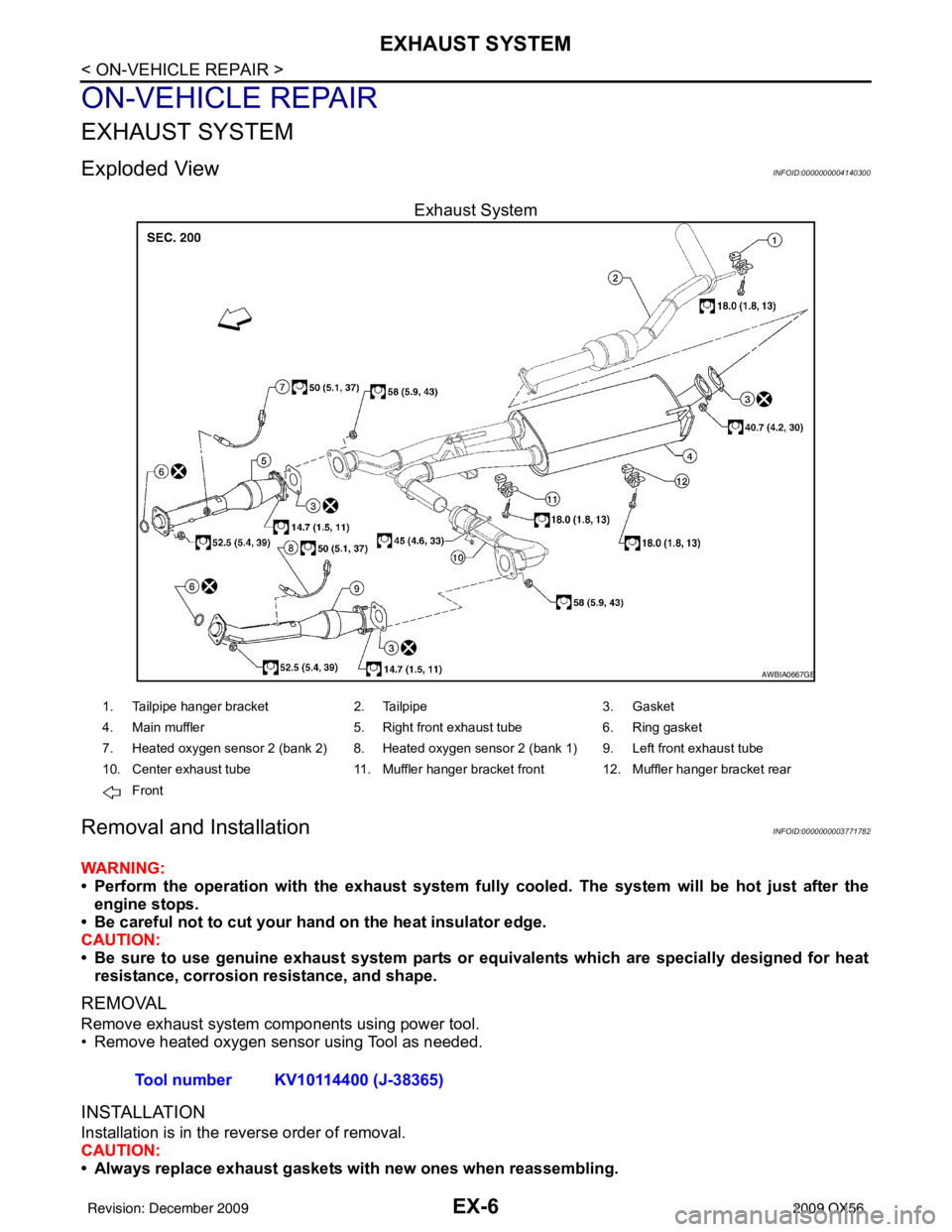
Exploded ViewINFOID:0000000004140300
Exhaust System
Removal and InstallationINFOID:0000000003771782
WARNING:
• Perform the operation with the exhaust system fully cooled. The system will be hot just after the
engine stops.
• Be careful not to cut your hand on the heat insulator edge.
CAUTION:
• Be sure to use genuine exhaust system parts or equivalents which are specially designed for heat
resistance, corrosion resistance, and shape.
REMOVAL
Remove exhaust system components using power tool.
• Remove heated oxygen sensor using Tool as needed.
INSTALLATION
Installation is in the reverse order of removal.
CAUTION:
• Always replace exhaust gaskets with new ones when reassembling.
AWBIA0667GB
1. Tailpipe hanger bracket 2. Tailpipe3. Gasket
4. Main muffler 5. Right front exhaust tube6. Ring gasket
7. Heated oxygen sensor 2 (bank 2) 8. Heated oxygen sensor 2 (bank 1) 9. Left front exhaust tube
10. Center exhaust tube 11. Muffler hanger bracket front 12. Muffler hanger bracket rear
Front
Tool number KV10114400 (J-38365)
Revision: December 20092009 QX56
Page 1949 of 4171

EXL-1
DRIVER CONTROLS
C
DE
F
G H
I
J
K
M
SECTION EXL
A
B
EXL
N
O P
CONTENTS
EXTERIOR LIGHTING SYSTEM
BASIC INSPECTION ....... .............................4
DIAGNOSIS AND REPAIR WORKFLOW ..... .....4
Work Flow ........................................................... ......4
FUNCTION DIAGNOSIS ...............................7
HEADLAMP .................................................... .....7
System Diagram .................................................. ......7
System Description ...................................................7
Component Parts Location ........................................7
Component Description .............................................7
DAYTIME LIGHT SYSTEM .................................9
System Diagram .................................................. ......9
System Description ...................................................9
Component Parts Location ........................................9
Component Description ...........................................10
AUTO LIGHT SYSTEM ......................................11
System Diagram ......................................................11
System Description .................................................11
Component Parts Location ......................................12
Component Description ...........................................12
HEADLAMP AIMING SYSTEM (MANUAL) .......13
System Diagram .................................................. ....13
System Description .................................................13
Component Parts Location ......................................13
Component Description ...........................................13
FRONT FOG LAMP ............................................14
System Diagram .................................................. ....14
System Description .................................................14
Component Parts Location ......................................14
Component Description ...........................................14
TURN SIGNAL AND HAZARD WARNING
LAMPS ...............................................................
15
System Diagram .................................................. ....15
System Description .................................................15
Component Parts Location ......................................15
Component Description ....................................... ....16
PARKING, LICENSE PLATE AND TAIL
LAMPS ..............................................................
17
System Diagram ......................................................17
System Description ..................................................17
Component Parts Location ......................................17
Component Description ...........................................18
TRAILER TOW ..................................................19
System Diagram ......................................................19
System Description ..................................................19
Component Parts Location ......................................20
Component Description ...........................................20
DIAGNOSIS SYSTEM (BCM) ...........................22
HEADLAMP ........................................................... ....22
HEADLAMP : CONSULT-III Function (BCM -
HEAD LAMP) ...........................................................
22
FLASHER ............................................................... ....23
FLASHER : CONSULT-III Function (BCM -
FLASHER) ...............................................................
23
COMB SW .............................................................. ....23
COMB SW : CONSULT-III Function (BCM -
COMB SW) ..............................................................
23
DIAGNOSIS SYSTEM (IPDM E/R) ...................25
Diagnosis Description ..............................................25
CONSULT - III Function (IPDM E/R) .......................27
COMPONENT DIAGNOSIS .........................30
POWER SUPPLY AND GROUND CIRCUIT ....30
BCM (BODY CONTROL MODULE) ...................... ....30
BCM (BODY CONTROL MODULE) : Diagnosis
Procedure ............................................................ ....
30
IPDM E/R (INTELLIGENT POWER DISTRIBU-
TION MODULE ENGINE ROOM) .......................... ....
31
Revision: December 20092009 QX56
Page 1950 of 4171

EXL-2
IPDM E/R (INTELLIGENT POWER DISTRIBU-
TION MODULE ENGINE ROOM) : Diagnosis Pro-
cedure .....................................................................
31
HEADLAMP (HI) CIRCUIT ................................32
Description ........................................................... ...32
Component Function Check ...................................32
Diagnosis Procedure - Without Daytime Light Sys-
tem ..........................................................................
32
Diagnosis Procedure - With Daytime Light System
...
33
HEADLAMP (LO) CIRCUIT ...............................35
Description ........................................................... ...35
Component Function Check ...................................35
Diagnosis Procedure - Without Daytime Light Sys-
tem ..........................................................................
35
Diagnosis Procedure - With Daytime Light System
...
36
FRONT FOG LAMP CIRCUIT ...........................38
Description ........................................................... ...38
Component Function Check ...................................38
Diagnosis Procedure ..............................................38
PARKING LAMP CIRCUIT ................................40
Description ........................................................... ...40
Component Function Check ...................................40
Diagnosis Procedure - Without Daytime Light Sys-
tem ..........................................................................
40
Diagnosis Procedure - With Daytime Light System
...
42
TURN SIGNAL LAMP CIRCUIT ........................46
Description ........................................................... ...46
Component Function Check ...................................46
Diagnosis Procedure ..............................................46
OPTICAL SENSOR ...........................................49
Description ..............................................................49
Component Function Check ...................................49
Diagnosis Procedure ..............................................49
HEADLAMP AIMING SWITCH ..........................51
Description ........................................................... ...51
Diagnosis Procedure - Without Daytime Light Sys-
tem ..........................................................................
51
Diagnosis Procedure - With Daytime Light System
...
52
HEADLAMP .......................................................53
Wiring Diagram .................................................... ...53
DAYTIME LIGHT SYSTEM ................................57
Wiring Diagram .................................................... ...57
AUTO LIGHT SYSTEM ......................................64
Wiring Diagram .................................................... ...64
HEADLAMP AIMING SYSTEM (MANUAL) ......71
Wiring Diagram .................................................... ...71
FRONT FOG LAMP SYSTEM ...........................75
Wiring Diagram .................................................... ...75
TURN SIGNAL AND HAZARD WARNING
LAMP SYSTEM .............................................. ...
78
Wiring Diagram .................................................... ...78
PARKING, LICENSE PLATE AND TAIL
LAMPS SYSTEM ...............................................
85
Wiring Diagram .................................................... ...85
STOP LAMP ......................................................91
Wiring Diagram .................................................... ...91
BACK-UP LAMP ............................................ ...95
Wiring Diagram .................................................... ...95
TRAILER TOW .................................................100
Wiring Diagram .....................................................100
ECU DIAGNOSIS ......................................106
BCM (BODY CONTROL MODULE) ............... ..106
Reference Value .................................................. .106
Terminal Layout ....................................................108
Physical Values .....................................................108
Wiring Diagram .....................................................114
Fail Safe ...............................................................118
DTC Inspection Priority Chart .............................119
DTC Index ............................................................119
IPDM E/R (INTELLIGENT POWER DISTRI-
BUTION MODULE ENGINE ROOM) ................
121
Reference Value .................................................. .121
Terminal Layout ....................................................123
Physical Values .....................................................123
Wiring Diagram .....................................................128
Fail Safe ...............................................................131
DTC Index ............................................................133
SYMPTOM DIAGNOSIS ...........................134
EXTERIOR LIGHTING SYSTEM SYMPTOMS ..134
Symptom Table .................................................... .134
NORMAL OPERATING CONDITION ...............136
Description ........................................................... .136
BOTH SIDE HEADLAMPS DO NOT SWITCH
TO HIGH BEAM ................................................
137
Description ........................................................... .137
Diagnosis Procedure .............................................137
BOTH SIDE HEADLAMPS (LO) ARE NOT
TURNED ON .....................................................
138
Description ............................................................138
Diagnosis Procedure .............................................138
PARKING, LICENSE PLATE AND TAIL
LAMPS ARE NOT TURNED ON ......................
139
Description ........................................................... .139
Revision: December 20092009 QX56
Page 1963 of 4171
TURN SIGNAL AND HAZARD WARNING LAMPSEXL-15
< FUNCTION DIAGNOSIS >
C
DE
F
G H
I
J
K
M A
B
EXL
N
O P
TURN SIGNAL AND HA ZARD WARNING LAMPS
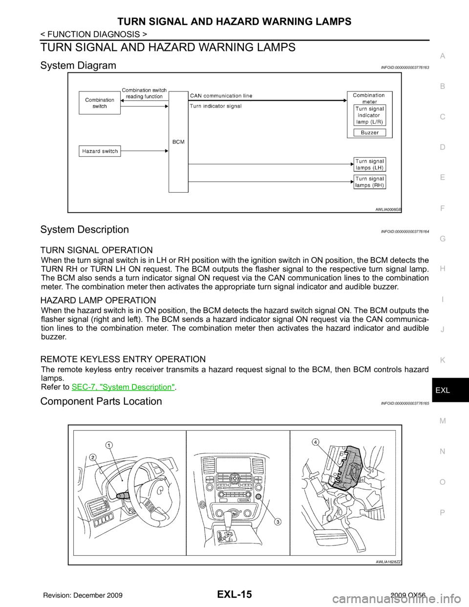
System DiagramINFOID:0000000003776163
System DescriptionINFOID:0000000003776164
TURN SIGNAL OPERATION
When the turn signal switch is in LH or RH position with the ignition switch in ON position, the BCM detects the
TURN RH or TURN LH ON request. The BCM outputs the fl asher signal to the respective turn signal lamp.
The BCM also sends a turn indicator signal ON reques t via the CAN communication lines to the combination
meter. The combination meter then activates the appropriate turn signal indicator and audible buzzer.
HAZARD LAMP OPERATION
When the hazard switch is in ON position, the BCM detects the hazard switch signal ON. The BCM outputs the
flasher signal (right and left). The BCM sends a hazar d indicator signal ON request via the CAN communica-
tion lines to the combination meter. The combinati on meter then activates the hazard indicator and audible
buzzer.
REMOTE KEYLESS ENTRY OPERATION
The remote keyless entry receiver transmits a hazard request signal to the BCM, then BCM controls hazard
lamps.
Refer to SEC-7, "
System Description".
Component Parts LocationINFOID:0000000003776165
AWLIA0006GB
AWLIA1628ZZ
Revision: December 20092009 QX56
Page 1964 of 4171

EXL-16
< FUNCTION DIAGNOSIS >
TURN SIGNAL AND HAZARD WARNING LAMPS
Component Description
INFOID:0000000003776166
1. Combination meter M23, M24 2. Combination switch M28 3. Hazard switch M55
4. BCM M18, M20 (view with instrument panel removed)
Part name Description
BCM Controls turn signal and hazard flasher operation.
Combination switch Lighting and turn signal switch requests are output to the BCM.
Hazard switch Hazard flasher request signal is output to the BCM.
Combination meter Outputs turn and hazard indicator as requested by the BCM.
Revision: December 20092009 QX56
Page 1973 of 4171
DIAGNOSIS SYSTEM (IPDM E/R)EXL-25
< FUNCTION DIAGNOSIS >
C
DE
F
G H
I
J
K
M A
B
EXL
N
O P
DIAGNOSIS SYSTEM (IPDM E/R)
Diagnosis DescriptionINFOID:0000000004215511
AUTO ACTIVE TEST
Description
In auto active test mode, the IPDM E/R sends a drive signal to the following systems to check their operation.
• Oil pressure low/coolant pressure high warning indicator
• Oil pressure gauge
• Rear window defogger
• Front wipers
• Tail, license and parking lamps
• Front fog lamps
• Headlamps (Hi, Lo)
• A/C compressor (magnetic clutch)
• Cooling fan
Operation Procedure
1. Close the hood and front door RH, and lift the wiper arms from the windshield (to prevent windshield dam-
age due to wiper operation).
NOTE:
When auto active test is performed with hood opened, sprinkle water on windshield before hand.
2. Turn ignition switch OFF.
3. Turn the ignition switch ON and, within 20 seconds, press the front door switch LH 10 times. Then turn the ignition switch OFF.
4. Turn the ignition switch ON within 10 seconds. Af ter that the horn sounds once and the auto active test
starts.
5. After a series of the following operations is repeated 3 times, auto active test is completed.
NOTE:
When auto active test mode has to be cancelled halfway through test, turn ignition switch OFF.
CAUTION:
• If auto active test mode cannot be actua ted, check door switch system. Refer to DLK-71, "
Descrip-
tion".
• Do not start the engine.
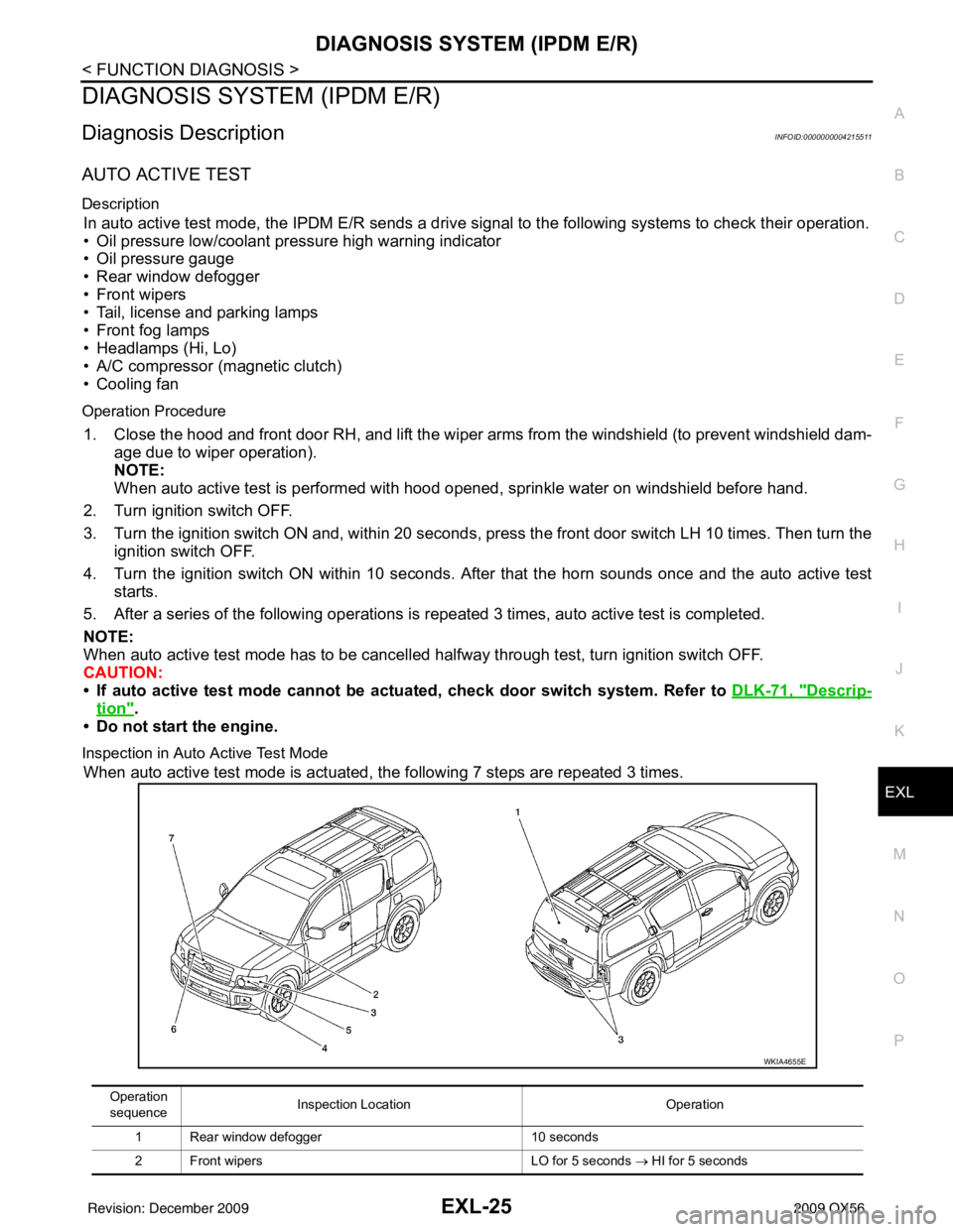
Inspection in Auto Active Test Mode
When auto active test mode is actuated, the following 7 steps are repeated 3 times.
Operation
sequence Inspection Location
Operation
1 Rear window defogger 10 seconds
2 Front wipers LO for 5 seconds → HI for 5 seconds
WKIA4655E
Revision: December 20092009 QX56