2009 INFINITI QX56 clutch
[x] Cancel search: clutchPage 3817 of 4171
SYSTEM SYMPTOMTM-169
< SYMPTOM DIAGNOSIS >
CEF
G H
I
J
K L
M A
B
TM
N
O P
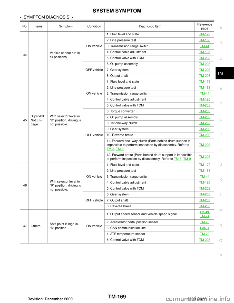
44
Slips/Will
Not En-
gage Vehicle cannot run in
all positions.
ON vehicle1. Fluid level and state
TM-179
2. Line pressure testTM-188
3. Transmission range switch TM-44
4. Control cable adjustmentTM-195
5. Control valve with TCMTM-203
OFF vehicle6. Oil pump assembly
TM-2037. Gear systemTM-203
8. Output shaftTM-203
45With selector lever in
“D” position, driving is
not possible. ON vehicle
1. Fluid level and state
TM-179
2. Line pressure testTM-188
3. Transmission range switch TM-44
4. Control cable adjustmentTM-195
5. Control valve with TCMTM-203
OFF vehicle6. Torque converter
TM-203
7. Oil pump assembly TM-203
8. 1st one-way clutchTM-203
9. Gear systemTM-203
10. Reverse brakeTM-203
11. Forward one- way clutch (Parts behind drum support is
impossible to perform inspection by disassembly. Refer to
TM-8
, TM-9
TM-203
12. Forward brake (Parts behind drum support is impossible
to perform inspection by disassembly. Refer to TM-8
, TM-9TM-203
46 With selector lever in
“R” position, driving is
not possible. ON vehicle
1. Fluid level and state
TM-179
2. Line pressure testTM-188
3. Transmission range switch TM-44
4. Control cable adjustmentTM-195
5. Control valve with TCMTM-203
OFF vehicle6. Gear system
TM-2037. Output shaftTM-203
8. Reverse brakeTM-203
47 OthersShift point is high in
“D” position. ON vehicle1. Output speed sensor and vehicle speed signal
TM-49
,
TM-74
2. Accelerator pedal position sensor TM-70
3. CAN communication line LAN-4
4. ATF temperature sensorTM-72
5. Control valve with TCMTM-203
No. Items Symptom Condition Diagnostic Item Reference
page
Revision: December 20092009 QX56
Page 3818 of 4171
TM-170
< SYMPTOM DIAGNOSIS >
SYSTEM SYMPTOM
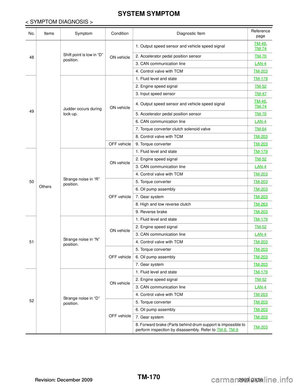
48Others Shift point is low in “D”
position.
ON vehicle1. Output speed sensor and vehicle speed signal
TM-49
,
TM-74
2. Accelerator pedal position sensor TM-70
3. CAN communication line LAN-4
4. Control valve with TCMTM-203
49Judder occurs during
lock-up. ON vehicle1. Fluid level and state
TM-179
2. Engine speed signal TM-52
3. Input speed sensorTM-47
4. Output speed sensor and vehicle speed signalTM-49,
TM-74
5. Accelerator pedal position sensor TM-70
6. CAN communication line LAN-4
7. Torque converter clutch solenoid valveTM-64
8. Control valve with TCMTM-203
OFF vehicle 9. Torque converter TM-203
50Strange noise in “R”
position. ON vehicle
1. Fluid level and state
TM-179
2. Engine speed signal TM-52
3. CAN communication line LAN-4
4. Control valve with TCMTM-203
OFF vehicle5. Torque converter
TM-203
6. Oil pump assemblyTM-203
7. Gear systemTM-203
8. High and low reverse clutchTM-263
9. Reverse brakeTM-203
51Strange noise in “N”
position. ON vehicle
1. Fluid level and state
TM-179
2. Engine speed signal TM-52
3. CAN communication line LAN-4
4. Control valve with TCMTM-203
OFF vehicle5. Torque converter
TM-2036. Oil pump assemblyTM-203
7. Gear systemTM-203
52Strange noise in “D”
position. ON vehicle
1. Fluid level and state
TM-179
2. Engine speed signal TM-52
3. CAN communication line LAN-4
4. Control valve with TCMTM-203
OFF vehicle5. Torque converter
TM-203
6. Oil pump assemblyTM-203
7. Gear systemTM-203
8. Forward brake (Parts behind drum support is impossible to
perform inspection by disassembly. Refer to TM-8
, TM-9TM-203
No. Items Symptom Condition Diagnostic Item Reference
page
Revision: December 20092009 QX56
Page 3819 of 4171
SYSTEM SYMPTOMTM-171
< SYMPTOM DIAGNOSIS >
CEF
G H
I
J
K L
M A
B
TM
N
O P
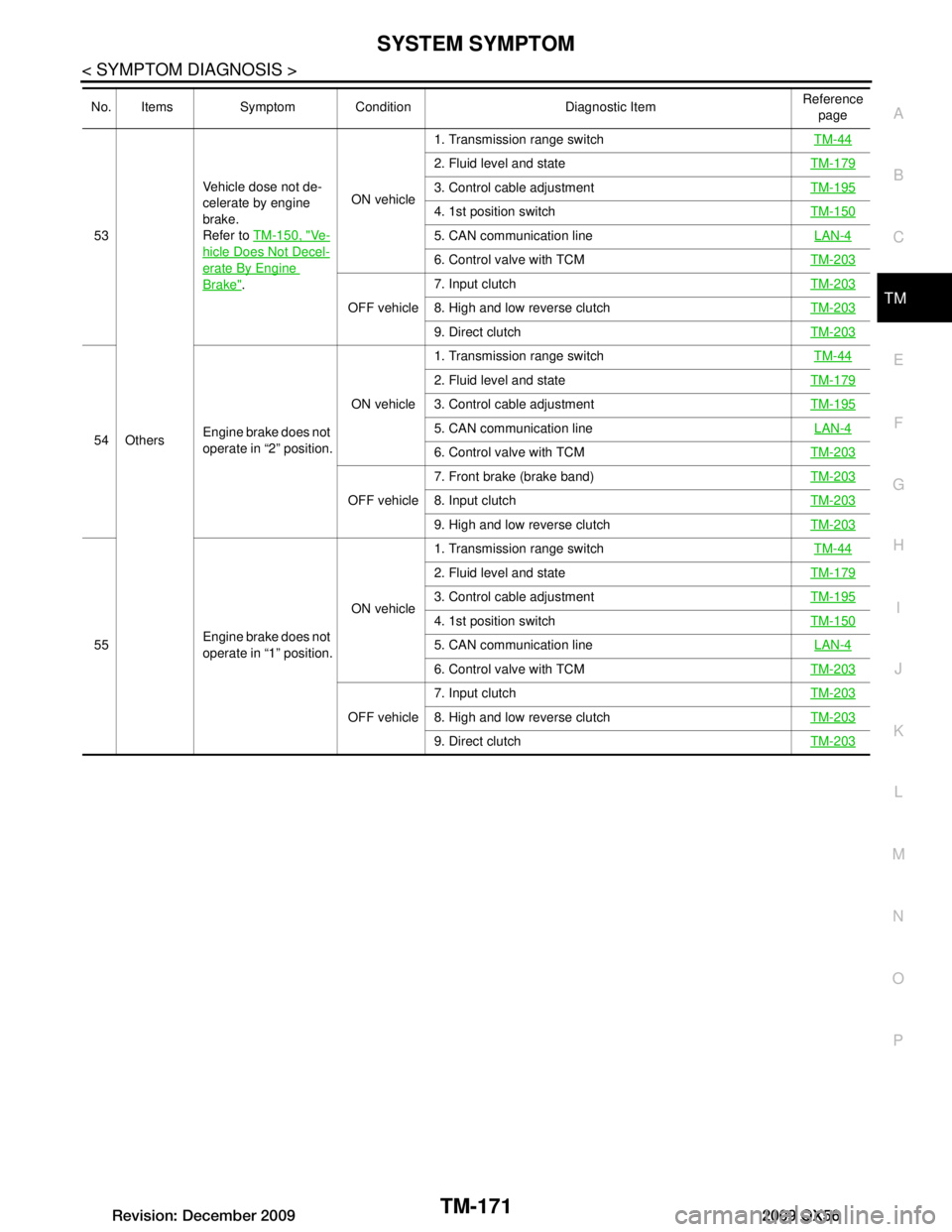
53
Others Vehicle dose not de-
celerate by engine
brake.
Refer to
TM-150, "Ve-
hicle Does Not Decel-
erate By Engine
Brake". ON vehicle
1. Transmission range switch
TM-44
2. Fluid level and stateTM-179
3. Control cable adjustmentTM-195
4. 1st position switchTM-150
5. CAN communication line LAN-4
6. Control valve with TCMTM-203
OFF vehicle7. Input clutch
TM-2038. High and low reverse clutchTM-203
9. Direct clutchTM-203
54Engine brake does not
operate in “2” position. ON vehicle1. Transmission range switch
TM-44
2. Fluid level and stateTM-179
3. Control cable adjustmentTM-195
5. CAN communication line LAN-4
6. Control valve with TCMTM-203
OFF vehicle7. Front brake (brake band)
TM-2038. Input clutchTM-203
9. High and low reverse clutchTM-203
55Engine brake does not
operate in “1” position. ON vehicle1. Transmission range switch
TM-44
2. Fluid level and stateTM-179
3. Control cable adjustmentTM-195
4. 1st position switchTM-150
5. CAN communication line LAN-4
6. Control valve with TCMTM-203
OFF vehicle7. Input clutch
TM-2038. High and low reverse clutchTM-203
9. Direct clutchTM-203
No. Items Symptom Condition Diagnostic Item Reference
page
Revision: December 20092009 QX56
Page 3820 of 4171
TM-172
< SYMPTOM DIAGNOSIS >
SYSTEM SYMPTOM
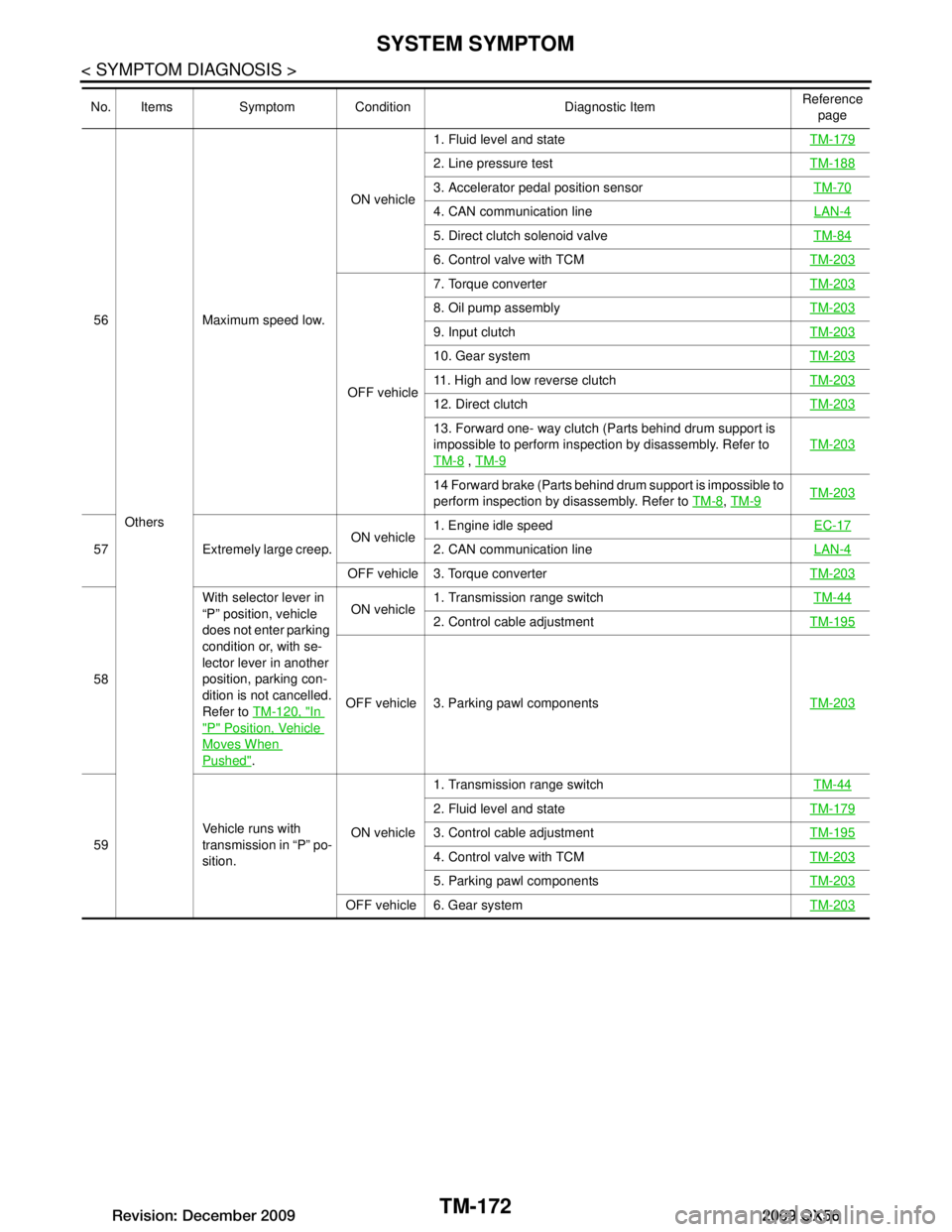
56Others Maximum speed low.
ON vehicle
1. Fluid level and state
TM-179
2. Line pressure testTM-188
3. Accelerator pedal position sensor TM-70
4. CAN communication line LAN-4
5. Direct clutch solenoid valveTM-84
6. Control valve with TCMTM-203
OFF vehicle7. Torque converter
TM-203
8. Oil pump assemblyTM-203
9. Input clutchTM-203
10. Gear systemTM-203
11. High and low reverse clutchTM-203
12. Direct clutchTM-203
13. Forward one- way clutch (Parts behind drum support is
impossible to perform inspection by disassembly. Refer to
TM-8
, TM-9
TM-203
14 Forward brake (Parts behind drum support is impossible to
perform inspection by disassembly. Refer to TM-8
, TM-9TM-203
57 Extremely large creep. ON vehicle1. Engine idle speed
EC-172. CAN communication lineLAN-4
OFF vehicle 3. Torque converter TM-203
58With selector lever in
“P” position, vehicle
does not enter parking
condition or, with se-
lector lever in another
position, parking con-
dition is not cancelled.
Refer to
TM-120, "In
"P" Position, Vehicle
Moves When
Pushed". ON vehicle
1. Transmission range switch
TM-44
2. Control cable adjustmentTM-195
OFF vehicle 3. Parking pawl components TM-203
59Vehicle runs with
transmission in “P” po-
sition. ON vehicle1. Transmission range switch
TM-44
2. Fluid level and stateTM-179
3. Control cable adjustmentTM-195
4. Control valve with TCMTM-203
5. Parking pawl componentsTM-203
OFF vehicle 6. Gear system TM-203
No. Items Symptom Condition Diagnostic Item Reference
page
Revision: December 20092009 QX56
Page 3821 of 4171
SYSTEM SYMPTOMTM-173
< SYMPTOM DIAGNOSIS >
CEF
G H
I
J
K L
M A
B
TM
N
O P
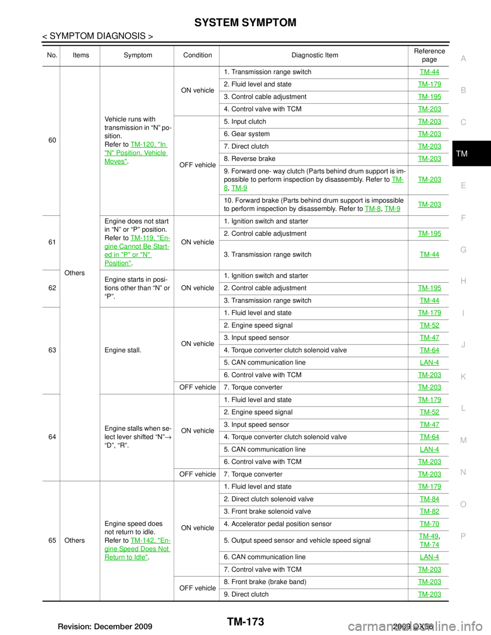
60
Others Vehicle runs with
transmission in “N” po-
sition.
Refer to
TM-120, "In
"N" Position, Vehicle
Moves". ON vehicle
1. Transmission range switch
TM-44
2. Fluid level and stateTM-179
3. Control cable adjustmentTM-195
4. Control valve with TCMTM-203
OFF vehicle5. Input clutch
TM-203
6. Gear systemTM-203
7. Direct clutchTM-203
8. Reverse brakeTM-203
9. Forward one- way clutch (Parts behind drum support is im-
possible to perform inspection by disassembly. Refer to TM-
8, TM-9
TM-203
10. Forward brake (Parts behind drum support is impossible
to perform inspection by disassembly. Refer to TM-8
, TM-9TM-203
61 Engine does not start
in “N” or “P” position.
Refer to
TM-119, "En-gine Cannot Be Start-
ed in "P" or "N"
Position". ON vehicle1. Ignition switch and starter
2. Control cable adjustment
TM-195
3. Transmission range switch TM-44
62Engine starts in posi-
tions other than “N” or
“P”.
ON vehicle1. Ignition switch and starter
2. Control cable adjustment
TM-195
3. Transmission range switch TM-44
63 Engine stall.ON vehicle1. Fluid level and state
TM-179
2. Engine speed signal TM-52
3. Input speed sensorTM-47
4. Torque converter clutch solenoid valveTM-64
5. CAN communication line LAN-4
6. Control valve with TCMTM-203
OFF vehicle 7. Torque converter TM-203
64Engine stalls when se-
lect lever shifted “N”
→
“D”, “R”. ON vehicle1. Fluid level and state
TM-179
2. Engine speed signal TM-52
3. Input speed sensorTM-47
4. Torque converter clutch solenoid valveTM-64
5. CAN communication line LAN-4
6. Control valve with TCMTM-203
OFF vehicle 7. Torque converter TM-203
65 OthersEngine speed does
not return to idle.
Refer to
TM-142, "En-
gine Speed Does Not
Return to Idle". ON vehicle 1. Fluid level and state
TM-179
2. Direct clutch solenoid valve TM-84
3. Front brake solenoid valveTM-82
4. Accelerator pedal position sensorTM-70
5. Output speed sensor and vehicle speed signalTM-49,
TM-74
6. CAN communication line LAN-4
7. Control valve with TCMTM-203
OFF vehicle8. Front brake (brake band)
TM-2039. Direct clutchTM-203
No. Items Symptom Condition Diagnostic Item Reference
page
Revision: December 20092009 QX56
Page 3824 of 4171
TM-176
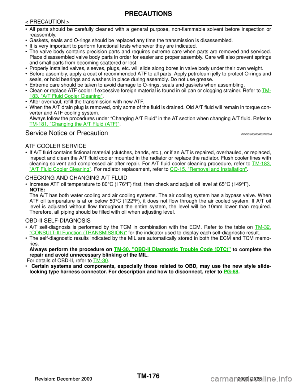
< PRECAUTION >
PRECAUTIONS
All parts should be carefully cleaned with a general purpose, non-flammable solvent before inspection orreassembly.
Gaskets, seals and O-rings should be replaced any time the transmission is disassembled.
It is very important to perform functional tests whenever they are indicated.
The valve body contains precision parts and requires extreme care when parts are removed and serviced. Place disassembled valve body parts in order for easier and proper assembly. Care will also prevent springs
and small parts from becoming scattered or lost.
Properly installed valves, sleeves, plugs, etc. will s lide along bores in valve body under their own weight.
Before assembly, apply a coat of recommended ATF to all parts. Apply petroleum jelly to protect O-rings and
seals, or hold bearings and washers in place during assembly. Do not use grease.
Extreme care should be taken to avoid damage to O-rings, seals and gaskets when assembling.
Clean or replace ATF cooler if excessive foreign material is found in oil pan or clogging strainer. Refer to TM-
183, "A/T Fluid Cooler Cleaning".
After overhaul, refill the transmission with new ATF.
When the A/T drain plug is removed, only some of the fluid is drained. Old A/T fluid will remain in torque con- verter and ATF cooling system.
Always follow the procedures under “Changing A/T Fluid” in the AT section when changing A/T fluid. Refer to
TM-181, "Changing the A/T Fluid (ATF)"
.
Service Notice or PrecautionINFOID:0000000003772016
ATF COOLER SERVICE
If A/T fluid contains fictional material (clutches, bands, etc.), or if an A/T is repaired, overhauled, or replaced,
inspect and clean the A/T fluid cooler mounted in the radiat or or replace the radiator. Flush cooler lines with
cleaning solvent and compressed air after repair. For A/T fluid cooler cleaning procedure, refer to TM-183,
"A/T Fluid Cooler Cleaning". For radiator replacement, refer to CO-15, "Removal and Installation".
CHECKING AND CHANGING A/T FLUID
Increase ATF oil temperature to 80 °C (176 °F) first, then check and adjust oil level at 65 °C (149 °F).
NOTE:
The A/T has both water cooling and air cooling systems . The air cooling system has a bypass valve. When
ATF oil temperature is at or below 50 °C (122 °F), it does not flow through the air cooled system. If A/T oil
level is adjusted without flow throughout the entir e system, the level will be 10mm lower than required.
Therefore, all piping should be filled with oil when adjusting level.
OBD-II SELF-DIAGNOSIS
A/T self-diagnosis is performed by the TCM in combination with the ECM. Refer to the table on TM-32,
"CONSULT-III Function (TRANSMISSION)" for the indicator used to display each self-diagnostic result.
The self-diagnostic results indicated by the MIL ar e automatically stored in both the ECM and TCM memo-
ries.
Always perform the procedure on TM-30, "OBD-II Diagnostic Trouble Code (DTC)"
to complete the
repair and avoid unnecessary blinking of the MIL.
For details of OBD-II, refer to TM-30
.
Certain systems and components, especially those related to OBD, may use the new style slide-
locking type harness connector. For descrip tion and how to disconnect, refer to PG-68
.
Revision: December 20092009 QX56
Page 3825 of 4171
PREPARATIONTM-177
< PREPARATION >
CEF
G H
I
J
K L
M A
B
TM
N
O P
PREPARATION
PREPARATION
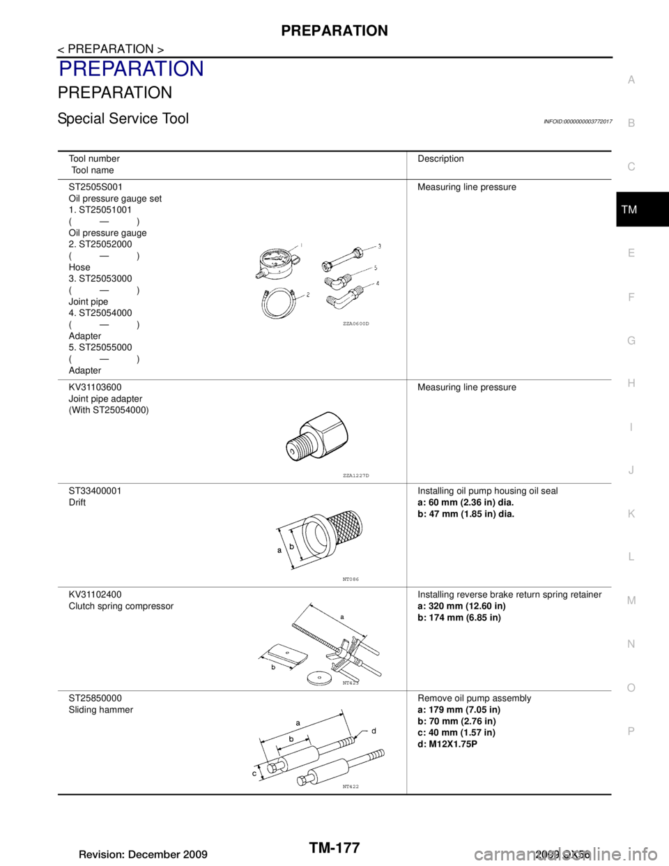
Special Service ToolINFOID:0000000003772017
Tool number
Tool name Description
ST2505S001
Oil pressure gauge set
1. ST25051001
(—)
Oil pressure gauge
2. ST25052000
(—)
Hose
3. ST25053000
(—)
Joint pipe
4. ST25054000
(—)
Adapter
5. ST25055000
(—)
Adapter Measuring line pressure
KV31103600
Joint pipe adapter
(With ST25054000) Measuring line pressure
ST33400001
Drift Installing oil pump housing oil seal
a: 60 mm (2.36 in) dia.
b: 47 mm (1.85 in) dia.
KV31102400
Clutch spring compressor Installing reverse brake
return spring retainer
a: 320 mm (12.60 in)
b: 174 mm (6.85 in)
ST25850000
Sliding hammer Remove oil pump assembly
a: 179 mm (7.05 in)
b: 70 mm (2.76 in)
c: 40 mm (1.57 in)
d: M12X1.75P
ZZA0600D
ZZA1227D
NT086
NT423
NT422
Revision: December 20092009 QX56
Page 3828 of 4171
TM-180
< ON-VEHICLE MAINTENANCE >
A/T FLUID
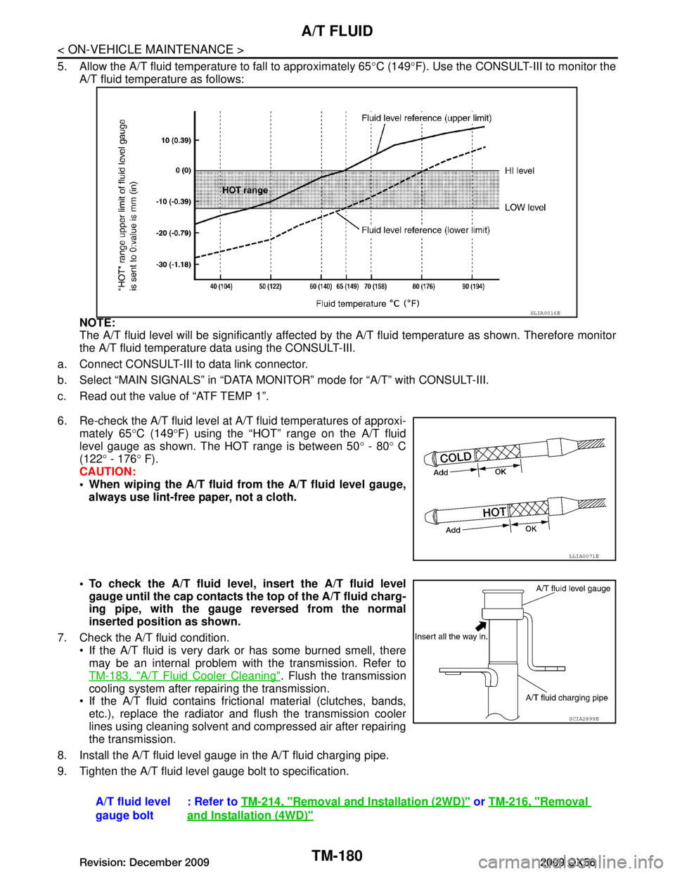
5. Allow the A/T fluid temperature to fall to approximately 65°C (149 °F). Use the CONSULT-III to monitor the
A/T fluid temperature as follows:
NOTE:
The A/T fluid level will be significantly affected by t he A/T fluid temperature as shown. Therefore monitor
the A/T fluid temperature data using the CONSULT-III.
a. Connect CONSULT-III to data link connector.
b. Select “MAIN SIGNALS” in “DATA MONI TOR” mode for “A/T” with CONSULT-III.
c. Read out the value of “ATF TEMP 1”.
6. Re-check the A/T fluid level at A/T fluid temperatures of approxi- mately 65 °C (149 °F) using the “HOT” range on the A/T fluid
level gauge as shown. The HOT range is between 50 ° - 80 ° C
(122 ° - 176 ° F).
CAUTION:
When wiping the A/T fluid from the A/T fluid level gauge,
always use lint-free paper, not a cloth.
To check the A/T fluid level , insert the A/T fluid level
gauge until the cap contacts th e top of the A/T fluid charg-
ing pipe, with the gauge reversed from the normal
inserted position as shown.
7. Check the A/T fluid condition. If the A/T fluid is very dark or has some burned smell, there
may be an internal problem with the transmission. Refer to
TM-183, "A/T Fluid Cooler Cleaning"
. Flush the transmission
cooling system after repairing the transmission.
If the A/T fluid contains frictional material (clutches, bands, etc.), replace the radiator and flush the transmission cooler
lines using cleaning solvent and compressed air after repairing
the transmission.
8. Install the A/T fluid level gauge in the A/T fluid charging pipe.
9. Tighten the A/T fluid level gauge bolt to specification.
SLIA0016E
LLIA0071E
A/T fluid level
gauge bolt : Refer to
TM-214, "Removal and Installation (2WD)" or TM-216, "Removal
and Installation (4WD)"
SCIA2899E
Revision: December 20092009 QX56