2009 INFINITI QX56 sunroof
[x] Cancel search: sunroofPage 2879 of 4171
PG-8
< BASIC INSPECTION >
INSPECTION AND ADJUSTMENT
INSPECTION AND ADJUSTMENT
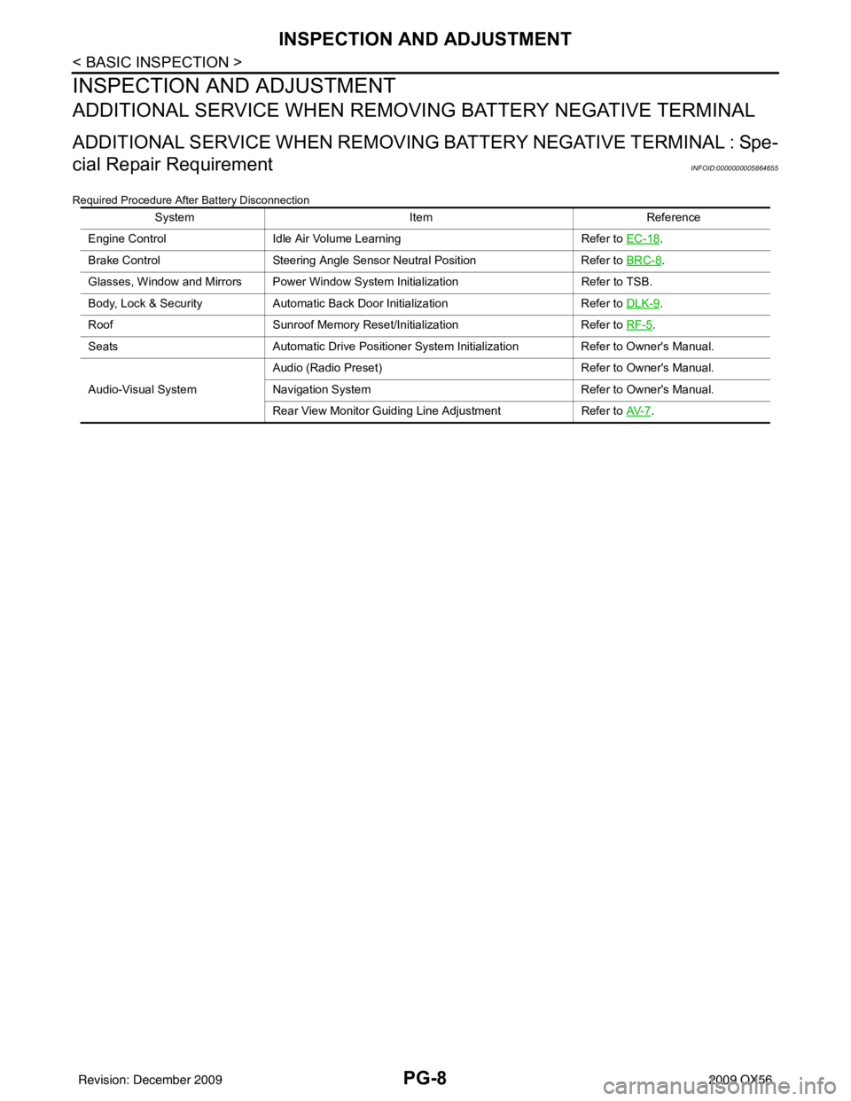
ADDITIONAL SERVICE WHEN REMOVING BATTERY NEGATIVE TERMINAL
ADDITIONAL SERVICE WHEN REMOVING BATTERY NEGATIVE TERMINAL : Spe-
cial Repair Requirement
INFOID:0000000005864655
Required Procedure After Battery Disconnection
System ItemReference
Engine Control Idle Air Volume Learning Refer to EC-18
.
Brake Control Steering Angle Sensor Neutral Position Refer to BRC-8
.
Glasses, Window and Mirrors Power Window System Initialization Refer to TSB.
Body, Lock & Security Automatic Back Door Initialization Refer to DLK-9
.
Roof Sunroof Memory Reset/Initialization Refer to RF-5
.
Seats Automatic Drive Positioner System Initialization Refer to Owner's Manual.
Audio-Visual System Audio (Radio Preset)
Refer to Owner's Manual.
Navigation System Refer to Owner's Manual.
Rear View Monitor Guiding Line Adjustment Refer to AV- 7
.
Revision: December 20092009 QX56
Page 2928 of 4171
PG
HARNESSPG-57
< COMPONENT DIAGNOSIS >
C
DE
F
G H
I
J
K L
B A
O P
N
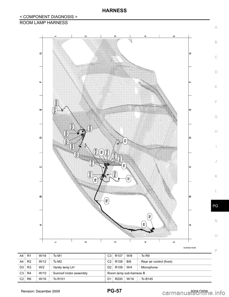
ROOM LAMP HARNESS
ALMIA0219GB
A4 R1 W/16 : To M1
C3 R107 W/8 : To R9
A4 R2 W/12 : To M2 C2 R108 B/6 : Rear air control (front)
D3 R3 W/2 : Vanity lamp LH D2 R109 W/4 : Microphone
C3 R4 W/10 : Sunroof motor assembly Room lamp sub-harness B
C2 R6 W/16 : To R101 D1 R200 W/16 : To B145
Revision: December 20092009 QX56
Page 2929 of 4171
PG-58
< COMPONENT DIAGNOSIS >
HARNESS
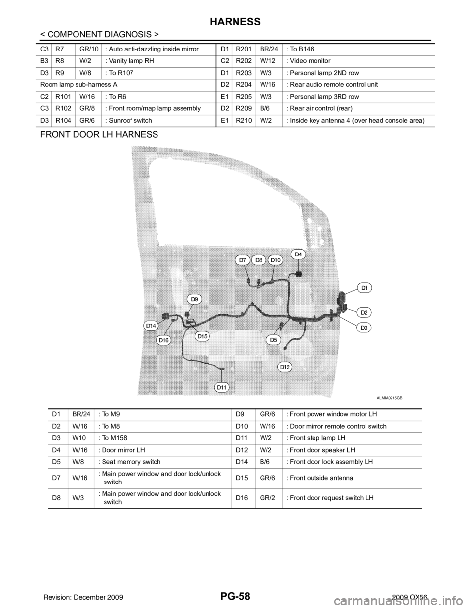
FRONT DOOR LH HARNESS
C3 R7 GR/10 : Auto anti-dazzling inside mirror D1 R201 BR/24 : To B146
B3 R8 W/2 : Vanity lamp RHC2 R202 W/12 : Video monitor
D3 R9 W/8 : To R107 D1 R203 W/3 : Personal lamp 2ND row
Room lamp sub-harness A D2 R204 W/16 : Rear audio remote control unit
C2 R101 W/16 : To R6 E1 R205 W/3 : Personal lamp 3RD row
C3 R102 GR/8 : Front room/map lamp assembly D2 R209 B/6 : Rear air control (rear)
D3 R104 GR/6 : Sunroof switch E1 R210 W/2 : Inside key antenna 4 (over head console area)
ALMIA0215GB
D1 BR/24 : To M9 D9 GR/6 : Front power window motor LH
D2 W/16 : To M8 D10 W/16 : Door mirror remote control switch
D3 W10 : To M158 D11 W/2 : Front step lamp LH
D4 W/16 : Door mirror LH D12 W/2 : Front door speaker LH
D5 W/8 : Seat memory switch D14 B/6 : Front door lock assembly LH
D7 W/16 : Main power window and door lock/unlock
switch D15 GR/6 : Front outside antenna
D8 W/3 : Main power window and door lock/unlock
switch
D16 GR/2 : Front door request switch LH
Revision: December 20092009 QX56
Page 3092 of 4171
RF-1
BODY EXTERIOR, DOORS, ROOF & VEHICLE SECURITY
C
DE
F
G H
I
J
L
M
SECTION RF
A
B
RF
N
O P
CONTENTS
ROOF
BASIC INSPECTION ....... .............................3
DIAGNOSIS AND REPAIR WORKFLOW ..... .....3
Work Flow ........................................................... ......3
INSPECTION AND ADJUSTMENT .....................5
ADDITIONAL SERVICE WHEN REPLACING
CONTROL UNIT .................................................... ......
5
ADDITIONAL SERVICE WHEN REPLACING
CONTROL UNIT : Description ..................................
5
ADDITIONAL SERVICE WHEN REPLACING
CONTROL UNIT : Special Repair Requirement .......
5
BASIC INSPECTION ...................................................5
BASIC INSPECTION : Spec ial Repair Require-
ment .................................................................... ......
5
FUNCTION DIAGNOSIS ...............................6
SUNROOF SYSTEM ...................................... .....6
System Diagram ................................................. ......6
System Description ...................................................6
Component Parts Location ......................................7
Component Description ............................................7
DIAGNOSIS SYSTEM (BCM) .............................8
COMMON ITEM ..................................................... ......8
COMMON ITEM : CONSULT-III Function (BCM -
COMMON ITEM) .......................................................
8
RETAINED PWR .........................................................8
RETAINED PWR : CONSULT-III Function (BCM -
RETAINED PWR) .....................................................
8
COMPONENT DIAGNOSIS .........................10
POWER SUPPLY AND GROUND CIRCUIT .. ....10
SUNROOF MOTOR ASSEMBLY .......................... ....10
SUNROOF MOTOR ASSEMBLY :
Diagnosis Procedure ..............................................
10
SUNROOF MOTOR ASSEMBLY : Special Repair
Requirement ........................................................ ....
11
SUNROOF SWITCH CIRCUIT ..........................12
Description ...............................................................12
Component Function Check ..................................12
Diagnosis Procedure ...............................................12
DOOR SWITCH .................................................14
Description ...............................................................14
Component Function Check ....................................14
Diagnosis Procedure ...............................................14
Component Inspection .............................................15
ECU DIAGNOSIS .........................................16
BCM (BODY CONTROL MODULE) .................16
Reference Value .................................................. ....16
Terminal Layout .......................................................18
Physical Values ................................................... ....18
Wiring Diagram ........................................................24
Fail Safe ..................................................................28
DTC Inspection Priority Chart ...............................29
DTC Index ...............................................................29
SUNROOF SYSTEM .........................................31
Reference Value ......................................................31
Wiring Diagram ........................................................32
SYMPTOM DIAGNOSIS ..............................37
SUNROOF DOES NOT OPERATE PROPER-
LY ......................................................................
37
Diagnosis Procedure ........................................... ....37
AUTO OPERATION DOES NOT OPERATE ....38
Diagnosis Procedure ...............................................38
DOES NOT STOP FULLY-OPEN OR FULLY-
CLOSED POSITION ..........................................
39
Diagnosis Procedure ...............................................39
Revision: December 20092009 QX56
Page 3093 of 4171

RF-2
RETAINED POWER OPERATION DOES NOT
OPERATE PROPERLY .....................................
40
Diagnosis Procedure ........................................... ...40
SUNROOF DOES NOT OPERATE ANTI-
PINCH FUNCTION .......................................... ...
41
Diagnosis Procedure ........................................... ...41
SQUEAK AND RATTLE TROUBLE DIAG-
NOSES ...............................................................
42
Work Flow ............................................................ ...42
Generic Squeak and Rattle Troubleshooting ..........44
Diagnostic Worksheet .............................................46
PRECAUTION .............................................48
PRECAUTIONS .............................................. ...48
Precaution for Supplemental Restraint System
(SRS) "AIR BAG" and "SEAT BELT PRE-TEN-
SIONER" .............................................................. ...
48
Precaution Necessary for Steering Wheel Rota-
tion After Battery Disconnect ..................................
48
Precaution ...............................................................49
PREPARATION ..........................................50
PREPARATION .............................................. ...50
Special Service Tool ............................................ ...50
Commercial Service Tool ........................................50
ON-VEHICLE REPAIR ...............................51
SUNROOF SYSTEM ...................................... ...51
Inspection ............................................................. ...51
Exploded View ........................................................54
Removal and Installation .........................................55
Revision: December 20092009 QX56
Page 3096 of 4171
INSPECTION AND ADJUSTMENTRF-5
< BASIC INSPECTION >
C
DE
F
G H
I
J
L
M A
B
RF
N
O P
INSPECTION AND ADJUSTMENT
ADDITIONAL SERVICE WHEN REPLACING CONTROL UNIT
ADDITIONAL SERVICE WHEN REPL ACING CONTROL UNIT : Description
INFOID:0000000003776061
MEMORY RESET PROCEDURE
1. Please observe the following instructi ons at confirming the sunroof operation.
NOTE:
Do not disconnect the electronic power while the sunroof is operating or within 5 seconds after the sunroof
stops. (to wipe-out the memory of lid position and operating friction.)
2. Initialization of system should be conducted after the following conditions.
• When the sunroof motor is changed.
• When the sunroof does not operate normally. (Incomplete initialization conditions)
ADDITIONAL SERVICE WHEN REPLACING CONTROL UNIT : Special Repair Re-
quirement
INFOID:0000000003776062
INITIALIZATION PROCEDURE
If the sunroof does not close or open automatically, us e the following procedure to return sunroof operation to
normal.
1. Turn ignition switch ON.
2. Push and hold the sunroof tilt switch in the forw ard (DOWN) position until the sunroof is fully closed.
3. After the sunroof has closed all the way, push and hold the tilt switch forward (DOWN) again for more than 2 seconds to re-learn motor position.
4. Initialization is complete if the sunroof operates normally.
BASIC INSPECTION
BASIC INSPECTION : Special Repair RequirementINFOID:0000000003776063
BASIC INSPECTION
1.INSPECTION START
1. Check the service history.
2. Check the following parts.
• Fuse/circuit breaker blown.
• Poor connection, open or short circuit of harness connector.
• Battery voltage.
Is the inspection result normal?
YES >> Inspection End.
NO >> Repair or replace the malfunctioning parts.
Revision: December 20092009 QX56
Page 3097 of 4171
RF-6
< FUNCTION DIAGNOSIS >
SUNROOF SYSTEM
FUNCTION DIAGNOSIS
SUNROOF SYSTEM
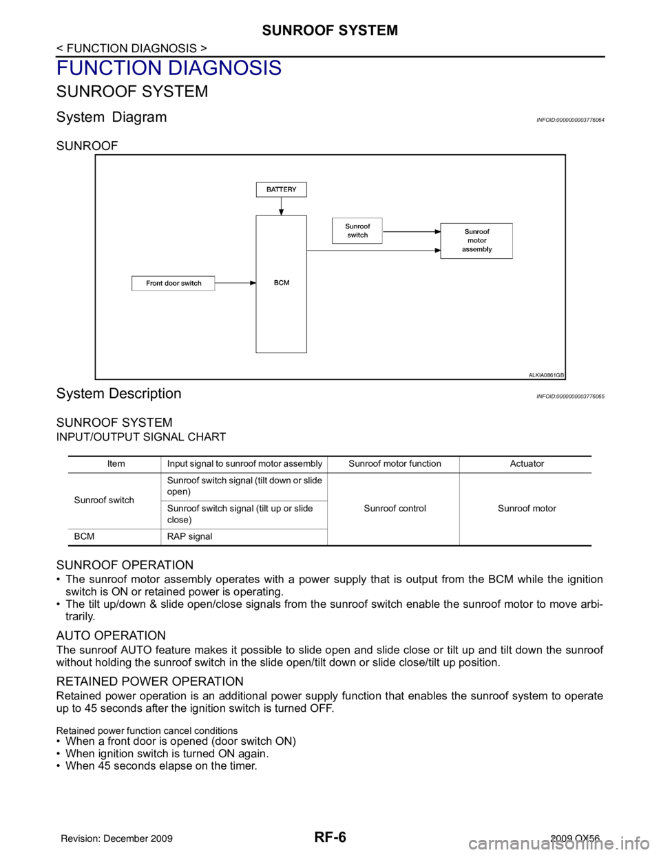
System DiagramINFOID:0000000003776064
SUNROOF
System DescriptionINFOID:0000000003776065
SUNROOF SYSTEM
INPUT/OUTPUT SIGNAL CHART
SUNROOF OPERATION
• The sunroof motor assembly operates with a power supply that is output from the BCM while the ignition
switch is ON or retained power is operating.
• The tilt up/down & slide open/close signals from the sunr oof switch enable the sunroof motor to move arbi-
trarily.
AUTO OPERATION
The sunroof AUTO feature makes it possible to sli de open and slide close or tilt up and tilt down the sunroof
without holding the sunroof switch in the slide open/tilt down or slide close/tilt up position.
RETAINED POWER OPERATION
Retained power operation is an additional power supply function that enables the sunroof system to operate
up to 45 seconds after the ignition switch is turned OFF.
Retained power function cancel conditions
• When a front door is opened (door switch ON)
• When ignition switch is turned ON again.
• When 45 seconds elapse on the timer.
ALKIA0861GB
Item Input signal to sunroof motor assembly Sunroof motor function Actuator
Sunroof switch Sunroof switch signal (tilt down or slide
open)
Sunroof controlSunroof motor
Sunroof switch signal (tilt up or slide
close)
BCM RAP signal
Revision: December 20092009 QX56
Page 3098 of 4171
SUNROOF SYSTEMRF-7
< FUNCTION DIAGNOSIS >
C
DE
F
G H
I
J
L
M A
B
RF
N
O P
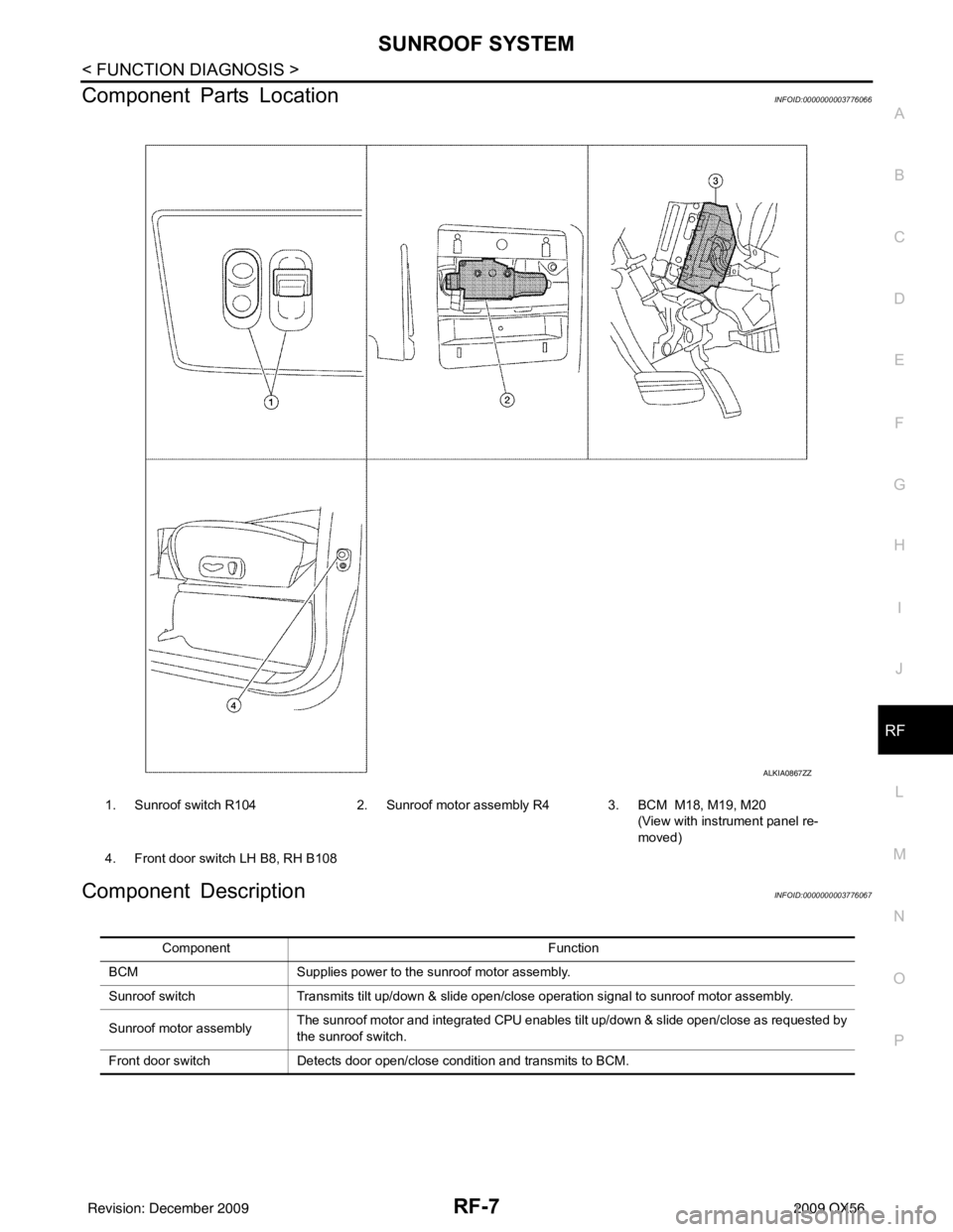
Component Parts LocationINFOID:0000000003776066
Component DescriptionINFOID:0000000003776067
ALKIA0867ZZ
1. Sunroof switch R104 2. Sunroof motor assembly R4 3. BCM M18, M19, M20
(View with instrument panel re-
moved)
4. Front door switch LH B8, RH B108
Component Function
BCM Supplies power to the sunroof motor assembly.
Sunroof switch Transmits tilt up/down & slide open/close operation signal to sunroof motor assembly.
Sunroof motor assembly The sunroof motor and integrated CPU enables tilt up/down & slide open/close as requested by
the sunroof switch.
Front door switch Detects door open/close condition and transmits to BCM.
Revision: December 20092009 QX56