2009 INFINITI QX56 fuel type
[x] Cancel search: fuel typePage 1811 of 4171
![INFINITI QX56 2009 Factory Service Manual
EC-484
< PREPARATION >[VK56DE]
PREPARATION
PREPARATION
PREPARATION
Special Service ToolINFOID:0000000003771744
The actual shapes of Kent-Moore tool
s may differ from those of special service tools il INFINITI QX56 2009 Factory Service Manual
EC-484
< PREPARATION >[VK56DE]
PREPARATION
PREPARATION
PREPARATION
Special Service ToolINFOID:0000000003771744
The actual shapes of Kent-Moore tool
s may differ from those of special service tools il](/manual-img/42/57031/w960_57031-1810.png)
EC-484
< PREPARATION >[VK56DE]
PREPARATION
PREPARATION
PREPARATION
Special Service ToolINFOID:0000000003771744
The actual shapes of Kent-Moore tool
s may differ from those of special service tools illustrated here.
Tool number
(Kent-Moore No.)
Tool nameDescription
EG17650301
(J-33984-A)
Radiator cap tester
adapter Adapting radiator cap tester to radiator cap and ra-
diator filler neck
a: 28 (1.10) dia.
b: 31.4 (1.236) dia.
c: 41.3 (1.626) dia.
Unit: mm (in)
KV10117100
(J-36471-A)
Heated oxygen sensor
wrench Loosening or tightening heated oxygen sensors
with 22 mm (0.87 in) hexagon nut
KV10114400
(J-38365)
Heated oxygen sensor
wrench Loosening or tightening heated oxygen sensors
a: 22 mm (0.87 in)
(J-44626)
Air fuel ratio (A/F) sen-
sor wrench Loosening or tightening air fuel ratio (A/F) sensor 1
(J-44321)
Fuel pressure gauge
kit Checking fuel pressure
(J-44321-6)
Fuel pressure adapter Connecting fuel pressure gauge to quick connec-
tor type fuel lines.
S-NT564
S-NT379
S-NT636
LEM054
LEC642
LBIA0376E
Revision: December 20092009 QX56
Page 1824 of 4171
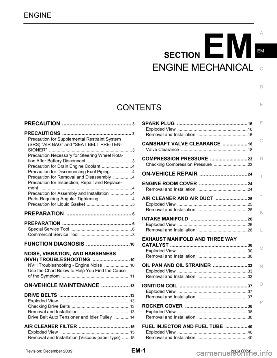
EM-1
ENGINE
C
DE
F
G H
I
J
K L
M
SECTION EM
A
EM
N
O P
CONTENTS
ENGINE MECHANICAL
PRECAUTION ....... ........................................3
PRECAUTIONS .............................................. .....3
Precaution for Supplemental Restraint System
(SRS) "AIR BAG" and "SEAT BELT PRE-TEN-
SIONER" ............................................................. ......
3
Precaution Necessary for Steering Wheel Rota-
tion After Battery Disconnect ............................... ......
3
Precaution for Drain Engine Coolant .........................4
Precaution for Disconnecting Fuel Piping .................4
Precaution for Removal and Disassembly ................4
Precaution for Inspection, Repair and Replace-
ment .................................................................... ......
4
Precaution for Assembly and Installation ..................4
Parts Requiring Angular Tightening ..........................4
Precaution for Liquid Gasket ............................... ......5
PREPARATION ............................................6
PREPARATION .............................................. .....6
Special Service Tool ........................................... ......6
Commercial Service Tool ..........................................8
FUNCTION DIAGNOSIS ..............................10
NOISE, VIBRATION, AND HARSHNESS
(NVH) TROUBLESHOOTING ........................ ....
10
NVH Troubleshooting - Engine Noise ................. ....10
Use the Chart Below to Help You Find the Cause
of the Symptom .......................................................
11
ON-VEHICLE MAINTENANCE ....................13
DRIVE BELTS ................................................ ....13
Exploded View .................................................... ....13
Checking Drive Belts ...............................................13
Removal and Installation .........................................13
Drive Belt Auto Tensioner and Idler Pulley ......... ....14
AIR CLEANER FILTER ......................................15
Exploded View .................................................... ....15
Removal and Installation (Viscous paper type) .......15
SPARK PLUG ...................................................16
Exploded View ..................................................... ....16
Removal and Installation .........................................16
CAMSHAFT VALVE CLEARANCE ..................18
Valve Clearance ......................................................18
COMPRESSION PRESSURE ...........................23
Checking Compression Pressure ............................23
ON-VEHICLE REPAIR .................................24
ENGINE ROOM COVER ...................................24
Removal and Installation ..................................... ....24
AIR CLEANER AND AIR DUCT .......................25
Exploded View .........................................................25
Removal and Installation .........................................25
INTAKE MANIFOLD .........................................26
Exploded View .........................................................26
Removal and Installation .........................................26
EXHAUST MANIFOLD AND THREE WAY
CATALYST ........................................................
30
Exploded View .........................................................30
Removal and Installation .........................................30
OIL PAN AND OIL STRAINER .........................33
Exploded View .........................................................33
Removal and Installation .........................................33
IGNITION COIL .................................................37
Exploded View .........................................................37
Removal and Installation .........................................37
ROCKER COVER .............................................38
Exploded View .........................................................38
Removal and Installation .........................................38
FUEL INJECTOR AND FUEL TUBE ................40
Exploded View .........................................................40
Removal and Installation .........................................40
Revision: December 20092009 QX56
Page 1902 of 4171
ENGINE ASSEMBLYEM-79
< REMOVAL AND INSTALLATION >
C
DE
F
G H
I
J
K L
M A
EM
NP
O
1. Release the fuel pressure. Refer to
EC-487, "Fuel Pressure Check".
2. Drain the engine coolant. Refer to CO-11, "
Changing Engine Coolant".
3. Drain the engine oil. Refer to LU-9, "
Changing Engine Oil".
4. Disconnect the battery negative and positive terminal. Refer to PG-76, "
Removal and Installation".
5. Remove the engine hood. Refer to DLK-230, "
Removal and Installation of Hood Assembly".
6. Remove the cowl extension. Refer to EXT-18, "
Removal and Installation".
7. Remove the air duct and air cleaner case assembly. Refer to EM-25, "
Removal and Installation".
8. Remove the radiator assembly and hoses. Refer to CO-15, "
Removal and Installation".
NOTE:
To prevent possible A/T fluid drain from transmissi on opening, use appropriate cap to close off transmis-
sion opening during operation.
9. Remove the drive belt. Refer to EM-13, "
Removal and Installation".
10. Remove the fan blade. Refer to CO-18, "
Removal and Installation (Crankshaft Driven Type)".
11. Disconnect the engine room harness from the fuse box and set it aside.
12. Disconnect the ECM.
13. Disconnect the engine room harness from the engine side and set it aside.
14. Disconnect the engine harness grounds.
15. Disconnect the power steering reservoir t ank from the engine and move it aside.
16. Disconnect the power steering oil pump from the engine. Move it aside and secure it using suitable wire or rope. Refer to ST-26, "
Removal and Installation"
17. Remove the A/C compressor bolts and set the compressor aside. Refer to HA-31, "Removal and Installa-
tion for Compressor" (ATC).
18. Disconnect the brake booster vacuum hose.
19. Disconnect the EVAP line.
20. Disconnect the fuel hose at the engine side connection. Refer to EM-40, "
Removal and Installation".
21. Disconnect the heater hoses at the cowl, and in stall plugs to avoid leakage of engine coolant.
22. Remove the A/T oil level indicator and indicator tube upper bolts.
23. Remove the front final drive assembly (4WD only). Refer to DLN-215, "
Removal and Installation".
24. Remove the exhaust manifolds. Refer to EM-30, "
Removal and Installation".
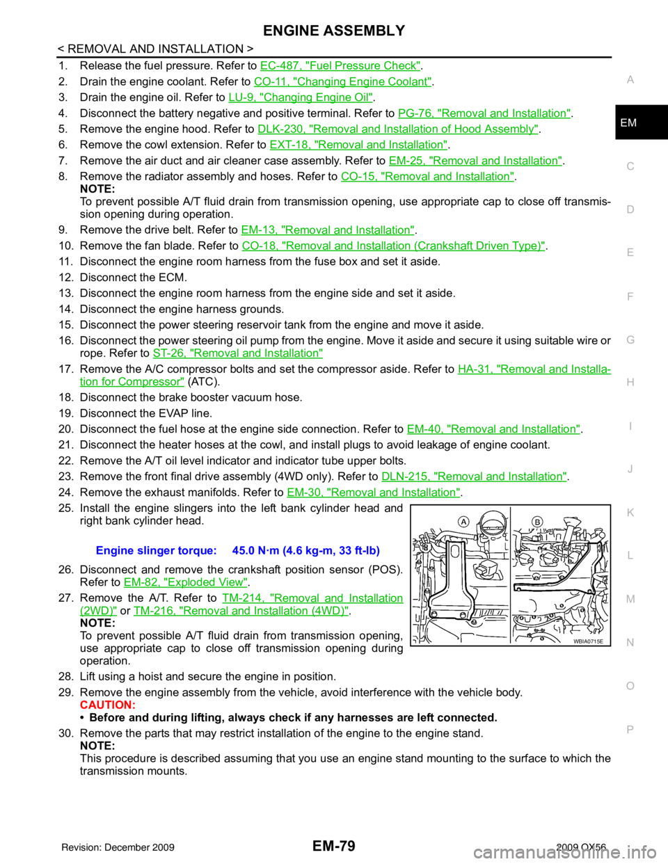
25. Install the engine slingers into the left bank cylinder head and right bank cylinder head.
26. Disconnect and remove the crankshaft position sensor (POS). Refer to EM-82, "
Exploded View".
27. Remove the A/T. Refer to TM-214, "
Removal and Installation
(2WD)" or TM-216, "Removal and Installation (4WD)".
NOTE:
To prevent possible A/T fluid drain from transmission opening,
use appropriate cap to close off transmission opening during
operation.
28. Lift using a hoist and secure the engine in position.
29. Remove the engine assembly from the vehicl e, avoid interference with the vehicle body.
CAUTION:
• Before and during lifting, always check if any harnesses are left connected.
30. Remove the parts that may restrict installation of the engine to the engine stand. NOTE:
This procedure is described assuming that you use an engine stand mounting to the surface to which the
transmission mounts. Engine slinger torque: 45.0 N·m (4.6 kg-m, 33 ft-lb)
WBIA0715E
Revision: December 20092009 QX56
Page 2176 of 4171
FSU-6
< ON-VEHICLE MAINTENANCE >
ON-VEHICLE SERVICE
ON-VEHICLE MAINTENANCE
ON-VEHICLE SERVICE
Front Suspension PartsINFOID:0000000003772269
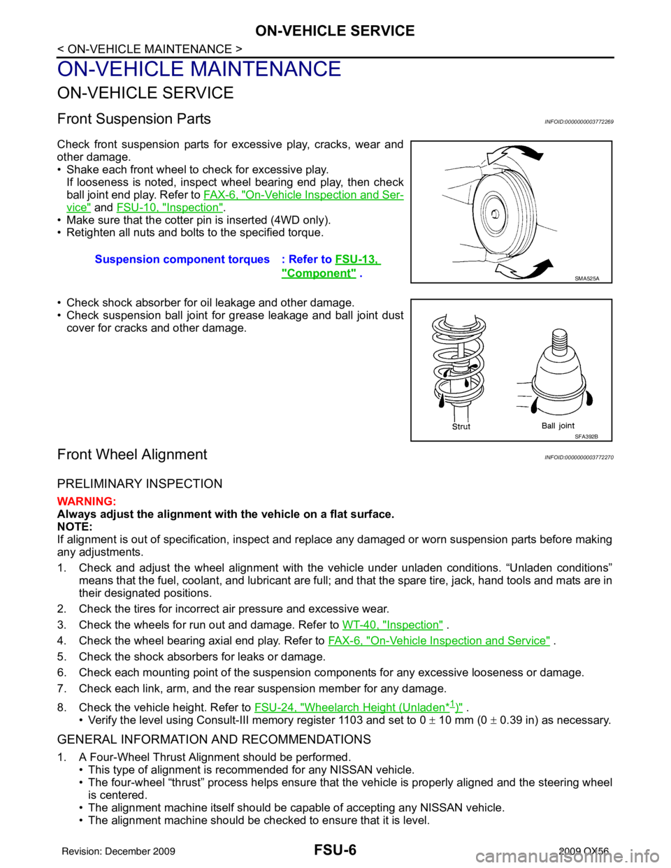
Check front suspension parts for excessive play, cracks, wear and
other damage.
• Shake each front wheel to check for excessive play.If looseness is noted, inspect wheel bearing end play, then check
ball joint end play. Refer to FA X - 6 , "
On-Vehicle Inspection and Ser-
vice" and FSU-10, "Inspection".
• Make sure that the cotter pin is inserted (4WD only).
• Retighten all nuts and bolts to the specified torque.
• Check shock absorber for oil leakage and other damage.
• Check suspension ball joint for grease leakage and ball joint dust cover for cracks and other damage.
Front Wheel AlignmentINFOID:0000000003772270
PRELIMINARY INSPECTION
WARNING:
Always adjust the alignment with the vehicle on a flat surface.
NOTE:
If alignment is out of specificat ion, inspect and replace any damaged or worn suspension parts before making
any adjustments.
1. Check and adjust the wheel alignment with the vehicle under unladen conditions. “Unladen conditions”
means that the fuel, coolant, and lubricant are full; and that the spare tire, jack, hand tools and mats are in
their designated positions.
2. Check the tires for incorrect air pressure and excessive wear.
3. Check the wheels for run out and damage. Refer to WT-40, "
Inspection" .
4. Check the wheel bearing axial end play. Refer to FA X - 6 , "
On-Vehicle Inspection and Service" .
5. Check the shock absorbers for leaks or damage.
6. Check each mounting point of the suspension components for any excessive looseness or damage.
7. Check each link, arm, and the rear suspension member for any damage.
8. Check the vehicle height. Refer to FSU-24, "
Wheelarch Height (Unladen*1)" .
• Verify the level using Consult-III memory register 1103 and set to 0 ± 10 mm (0 ± 0.39 in) as necessary.
GENERAL INFORMATION AND RECOMMENDATIONS
1. A Four-Wheel Thrust Alignment should be performed.
• This type of alignment is recommended for any NISSAN vehicle.
• The four-wheel “thrust” process helps ensure that the vehicle is properly aligned and the steering wheel
is centered.
• The alignment machine itself should be ca pable of accepting any NISSAN vehicle.
• The alignment machine should be checked to ensure that it is level. Suspension component
torques : Refer to FSU-13,
"Component" . SMA525A
SFA392B
Revision: December 20092009 QX56
Page 2193 of 4171
SERVICE DATA AND SPECIFICATIONS (SDS)FSU-23
< SERVICE DATA AND SPECIFICATIONS (SDS)
C
DF
G H
I
J
K L
M A
B
FSU
N
O P
SERVICE DATA AND SPECIFICATIONS (SDS)
SERVICE DATA AND SPECIFICATIONS (SDS)
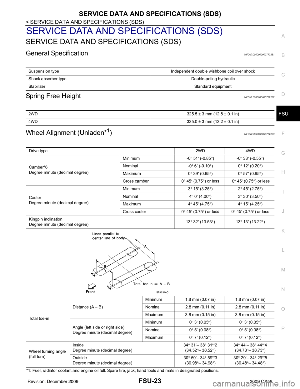
General SpecificationINFOID:0000000003772281
Spring Free HeightINFOID:0000000003772282
Wheel Alignment (Unladen*1)INFOID:0000000003772283
*1: Fuel, radiator coolant and engine oil full. Spare tire, jack, hand tools and mats in designated positions. Suspension type
Independent double wishbone coil over shock
Shock absorber type Double-acting hydraulic
Stabilizer Standard equipment
2WD325.5 ± 3 mm (12.8 ± 0.1 in)
4WD 335.0 ± 3 mm (13.2 ± 0.1 in)
Drive type 2WD 4WD
Camber*6
Degree minute (decimal degree) Minimum
-0° 51 ′ (-0.85 °)- 0° 33 ′ (-0.55 °)
Nominal -0° 6 ′ (-0.10 °)0 ° 12 ′ (0.20 °)
Maximum 0° 39 ′ (0.65 °)0 ° 57 ′ (0.95 °)
Cross camber 0° 45 ′ (0.75 °) or less 0 ° 45′ (0.75 °) or less
Caster
Degree minute (decimal degree) Minimum
3° 15 ′ (3.25 °)2 ° 45 ′ (2.75 °)
Nominal 4° 0 ′ (4.00 °)3 ° 30 ′ (3.50 °)
Maximum 4° 45 ′ (4.75 °)4 ° 15 ′ (4.25 °)
Cross caster 0° 45 ′ (0.75 °) or less 0
° 45 ′ (0
.75°) or less
Kingpin inclination
Degree minute (decimal degree) 13
° 32 ′ (13.53 °)1 3° 13 ′ (13.22 °)
Total toe-in Distance (A
− B) Minimum
1.8 mm (0.07 in) 1.8 mm (0.07 in)
Nominal 2.8 mm (0.11 in) 2.8 mm (0.11 in)
Maximum 3.8 mm (0.15 in) 3.8 mm (0.15 in)
Angle (left side or right side)
Degree minute (decimal degree) Minimum
0° 3 ′ (0.05 °)0 ° 3 ′ (0.05 °)
Nominal 0° 5 ′ (0.08 °)0 ° 5 ′ (0.08 °)
Maximum 0° 7 ′ (0.12 °)0 ° 7 ′ (0.12 °)
Wheel turning angle
(full turn) Inside
Degree minute (decimal degree)
34
° 31 ′– 38 ° 31 ′*2
(34.52 °– 38.52° ) 34
° 44 ′– 38° 44′*4
(34.73 °– 38.73 °)
Ou t
side
Degree minute (decimal degree) 30
° 59 ′– 34 ° 59 ′*3
(30.98 °– 34.98° ) 30
° 29 ′– 34° 29′*5
(30.48 °– 34.48 °)
SFA234AC
Revision: December 20092009 QX56
Page 2194 of 4171
FSU-24
< SERVICE DATA AND SPECIFICATIONS (SDS)
SERVICE DATA AND SPECIFICATIONS (SDS)
*2: Target value 37° 31 ′ (37.52 °)
*3: Target value 33 ° 59 ′ (33.98 °)
*4: Target value 37 ° 44 ′ (37.73 °)
*5: Target value 33 ° 29 ′ (33.48 °)
*6 Some vehicles may not be equipped with straight (non-adjustable) lower link bolts and washers. In order to adjust camber and caster
on these vehicles, first replace the lower link bolts and washers with adjustable (cam) bolts and washers
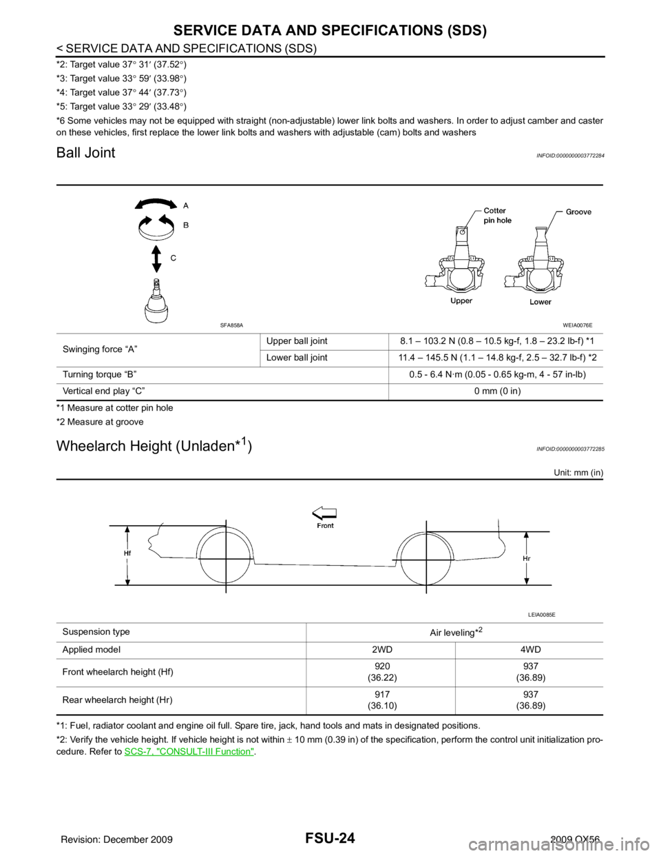
Ball JointINFOID:0000000003772284
*1 Measure at cotter pin hole
*2 Measure at groove
Wheelarch Height (Unladen*1)INFOID:0000000003772285
Unit: mm (in)
*1: Fuel, radiator coolant and engine oil full. Spare tire, jack, hand tools and mats in designated positions.
*2: Verify the vehicle height. If vehicle height is not within ± 10 mm (0.39 in) of the specification, perform the control unit initialization pro-
cedure. Refer to SCS-7, "
CONSULT-III Function".
Swinging force “A”
Upper ball joint
8.1 – 103.2 N (0.8 – 10.5 kg-f, 1.8 – 23.2 lb-f) *1
Lower ball joint 11.4 – 145.5 N (1.1 – 14.8 kg-f, 2.5 – 32.7 lb-f) *2
Turning torque “B” 0.5 - 6.4 N·m (0.05 - 0.65 kg-m, 4 - 57 in-lb)
Vertical end play “C” 0 mm (0 in)
SFA858AWEIA0076E
Suspension type
Air leveling*2
Applied model2WD4WD
Front wheelarch height (Hf) 920
(36.22) 937
(36.89)
Rear wheelarch height (Hr) 917
(36.10) 937
(36.89)
LEIA0085E
Revision: December 20092009 QX56
Page 2681 of 4171
MA-8
< ON-VEHICLE MAINTENANCE >
PERIODIC MAINTENANCE
PERIODIC MAINTENANCE
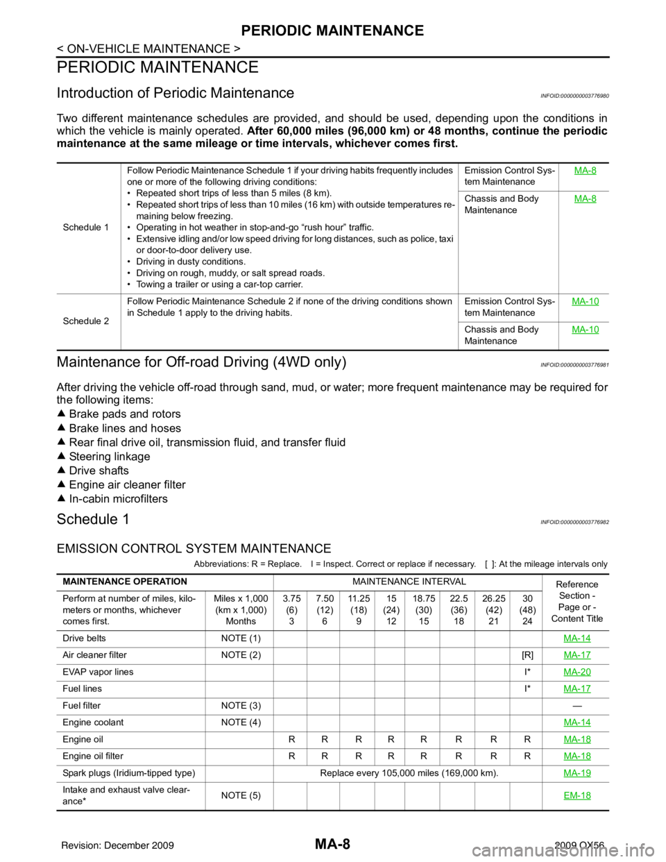
Introduction of Periodic MaintenanceINFOID:0000000003776980
Two different maintenance schedules are provided, and should be used, depending upon the conditions in
which the vehicle is mainly operated. After 60,000 miles (96,000 km) or 48 months, continue the periodic
maintenance at the same mileage or ti me intervals, whichever comes first.
Maintenance for Off-road Driving (4WD only)INFOID:0000000003776981
After driving the vehicle off-road through sand, mud, or water; more frequent maintenance may be required for
the following items:
Brake pads and rotors
Brake lines and hoses
Rear final drive oil, transmission fluid, and transfer fluid
Steering linkage
Drive shafts
Engine air cleaner filter
In-cabin microfilters
Schedule 1INFOID:0000000003776982
EMISSION CONTROL SYSTEM MAINTENANCE
Abbreviations: R = Replace. I = Inspect. Correct or r eplace if necessary. [ ]: At the mileage intervals only
Schedule 1Follow Periodic Maintenance Schedule 1 if your driving habits frequently includes
one or more of the following driving conditions:
• Repeated short trips of less than 5 miles (8 km).
• Repeated short trips of less than 10 miles (16 km) with outside temperatures re-
maining below freezing.
• Operating in hot weather in stop-and-go “rush hour” traffic.
• Extensive idling and/or low speed driving for long distances, such as police, taxi
or door-to-door delivery use.
• Driving in dusty conditions.
• Driving on rough, muddy, or salt spread roads.
• Towing a trailer or using a car-top carrier. Emission Control Sys-
tem Maintenance
MA-8
Chassis and Body
Maintenance
MA-8
Schedule 2Follow Periodic Maintenance Schedule 2 if none of the driving conditions shown
in Schedule 1 apply to the driving habits.
Emission Control Sys-
tem MaintenanceMA-10Chassis and Body
Maintenance
MA-10
MAINTENANCE OPERATION
MAINTENANCE INTERVAL
Reference
Section -
Page or -
Content Title
Perform at number of miles, kilo-
meters or months, whichever
comes first. Miles x 1,000
(km x 1,000) Months 3.75
(6)3 7.50
(12) 6 11 . 2 5
(18) 9 15
(24) 12 18.75
(30)15 22.5
(36) 18 26.25
(42)21 30
(48) 24
Drive belts NOTE (1) MA-14
Air cleaner filterNOTE (2) [R]MA-17
EVAP vapor lines I*MA-20
Fuel lines I*MA-17
Fuel filter NOTE (3) —
Engine coolant NOTE (4) MA-14
Engine oilR R R R R R R R MA-18
Engine oil filterR R R R R R R R MA-18
Spark plugs (Iridium-tipped type)Replace every 105,000 miles (169,000 km).MA-19
Intake and exhaust valve clear-
ance*NOTE (5)
EM-18
Revision: December 20092009 QX56
Page 2682 of 4171
PERIODIC MAINTENANCEMA-9
< ON-VEHICLE MAINTENANCE >
C
DE
F
G H
I
J
K L
M B
MA
N
O A
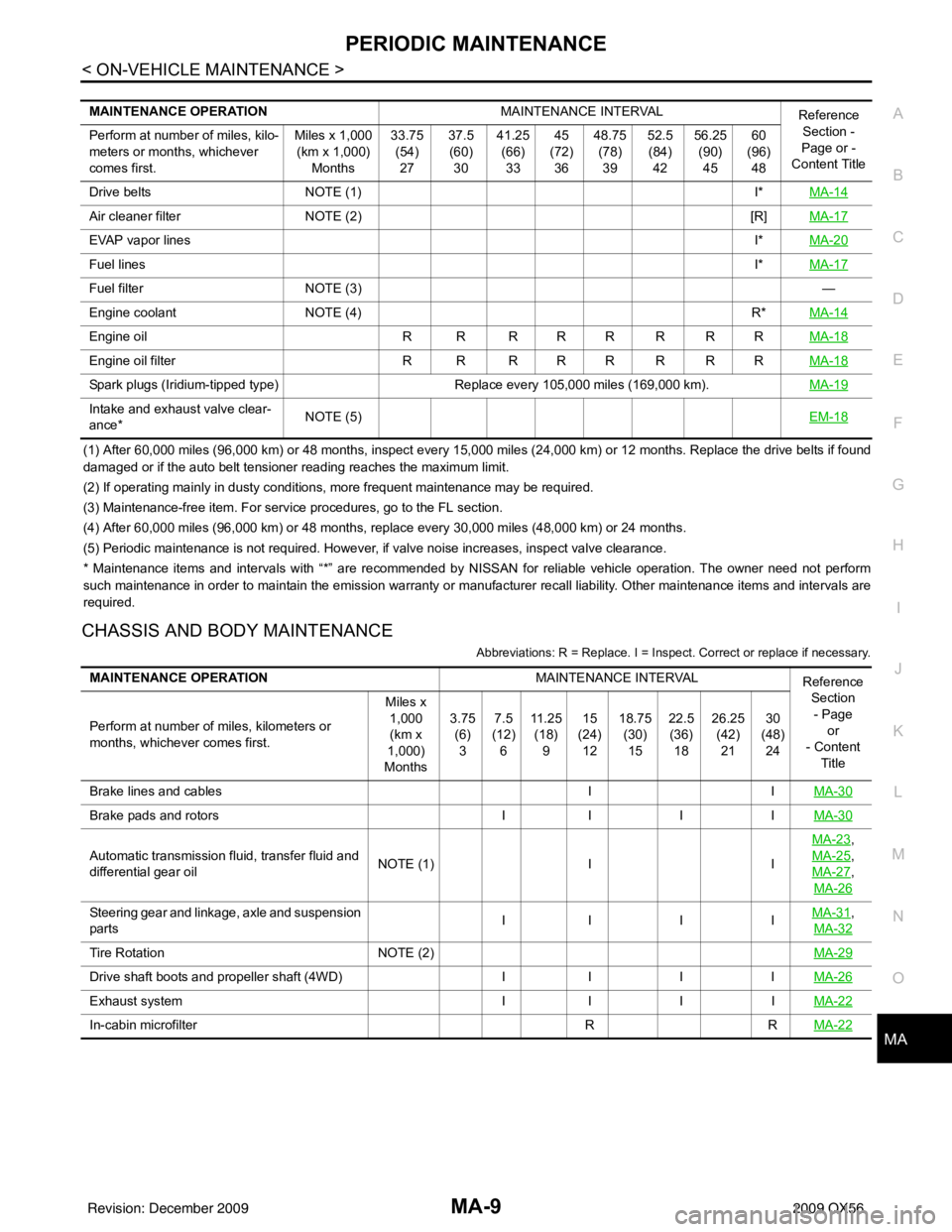
(1) After 60,000 miles (96,000 km) or 48 months, inspect every 15,000 miles (24,000 km) or 12 months. Replace the drive belts i
f found
damaged or if the auto belt tensioner reading reaches the maximum limit.
(2) If operating mainly in dusty conditions, more frequent maintenance may be required.
(3) Maintenance-free item. For service procedures, go to the FL section.
(4) After 60,000 miles (96,000 km) or 48 months, replace every 30,000 miles (48,000 km) or 24 months.
(5) Periodic maintenance is not required. However, if valve noise increases, inspect valve clearance.
* Maintenance items and inte rvals with “*” are recommended by NISSAN for reliable vehicle operation. The owner need not perform
such maintenance in order to maintain the emission warranty or manufacturer recall liability. Other maintenance items and inter vals are
required.
CHASSIS AND BODY MAINTENANCE
Abbreviations: R = Replace. I = Inspect. Correct or replace if necessary.
MAINTENANCE OPERATION MAINTENANCE INTERVAL
Reference
Section -
Page or -
Content Title
Perform at number of miles, kilo-
meters or months, whichever
comes first. Miles x 1,000
(km x 1,000) Months 33.75
(54)27 37.5
(60) 30 41.25
(66)33 45
(72) 36 48.75
(78)39 52.5
(84) 42 56.25
(90)45 60
(96) 48
Drive belts NOTE (1) I*MA-14
Air cleaner filter NOTE (2) [R]MA-17
EVAP vapor lines I*MA-20
Fuel lines I*MA-17
Fuel filter NOTE (3) —
Engine coolant NOTE (4) R*MA-14
Engine oil R R R R R R R R MA-18
Engine oil filterR R R R R R R R MA-18
Spark plugs (Iridium-tipped type)Replace every 105,000 miles (169,000 km).MA-19
Intake and exhaust valve clear-
ance*NOTE (5)
EM-18
MAINTENANCE OPERATIONMAINTENANCE INTERVAL
Reference
Section
- Page or
- Content
Title
Perform at number of miles, kilometers or
months, whichever comes first. Miles x
1,000(km x
1,000)
Months 3.75
(6)
3 7.5
(12)
6 11 . 2 5
(18)
9 15
(24)
12 18.75
(30)
15 22.5
(36)
18 26.25
(42)
21 30
(48)
24
Brake lines and cables IIMA-30
Brake pads and rotors II I IMA-30
Automatic transmission fluid, transfer fluid and
differential gear oil NOTE (1)
IIMA-23
,
MA-25
,
MA-27
,
MA-26
Steering gear and linkage, axle and suspension
parts II I I
MA-31,
MA-32
Tire Rotation NOTE (2) MA-29
Drive shaft boots and propeller shaft (4WD)II I IMA-26
Exhaust system II I IMA-22
In-cabin microfilter RRMA-22
Revision: December 20092009 QX56