2009 INFINITI QX56 oil pressure
[x] Cancel search: oil pressurePage 3814 of 4171
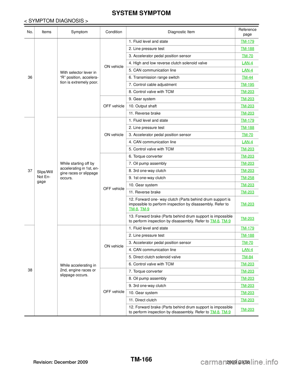
TM-166
< SYMPTOM DIAGNOSIS >
SYSTEM SYMPTOM
36Slips/Will
Not En-
gage With selector lever in
“R” position
, accelera-
tion is extremely poor. ON vehicle1. Fluid level and state
TM-179
2. Line pressure testTM-188
3. Accelerator pedal position sensor TM-70
4. High and low reverse clutch solenoid valve LAN-4
5. CAN communication lineLAN-4
6. Transmission range switchTM-44
7. Control cable adjustmentTM-195
8. Control valve with TCMTM-203
OFF vehicle9. Gear system
TM-20310. Output shaftTM-203
11. Reverse brakeTM-203
37While starting off by
accelerating in 1st, en-
gine races or slippage
occurs. ON vehicle
1. Fluid level and state
TM-179
2. Line pressure testTM-188
3. Accelerator pedal position sensor TM-70
4. CAN communication line LAN-4
5. Control valve with TCMTM-203
OFF vehicle6. Torque converter
TM-203
7. Oil pump assemblyTM-203
8. 3rd one-way clutchTM-203
9. 1st one-way clutchTM-258
10. Gear systemTM-203
11. Reverse brakeTM-203
12. Forward one- way clutch (Parts behind drum support is
impossible to perform inspection by disassembly. Refer to
TM-8
, TM-9
TM-203
13. Forward brake (Parts behind drum support is impossible
to perform inspection by disassembly. Refer to TM-8
, TM-9TM-203
38 While accelerating in
2nd, engine races or
slippage occurs. ON vehicle
1. Fluid level and state
TM-179
2. Line pressure testTM-188
3. Accelerator pedal position sensor TM-70
4. CAN communication line LAN-4
5. Direct clutch solenoid valveTM-84
6. Control valve with TCMTM-203
OFF vehicle7. Torque converter
TM-203
8. Oil pump assemblyTM-203
9. 3rd one-way clutchTM-203
10. Gear systemTM-203
11. Direct clutchTM-203
12. Forward brake (Parts behind drum support is impossible
to perform inspection by disassembly. Refer to TM-8
, TM-9TM-203
No. Items Symptom Condition Diagnostic Item Reference
page
Revision: December 20092009 QX56
Page 3815 of 4171
SYSTEM SYMPTOMTM-167
< SYMPTOM DIAGNOSIS >
CEF
G H
I
J
K L
M A
B
TM
N
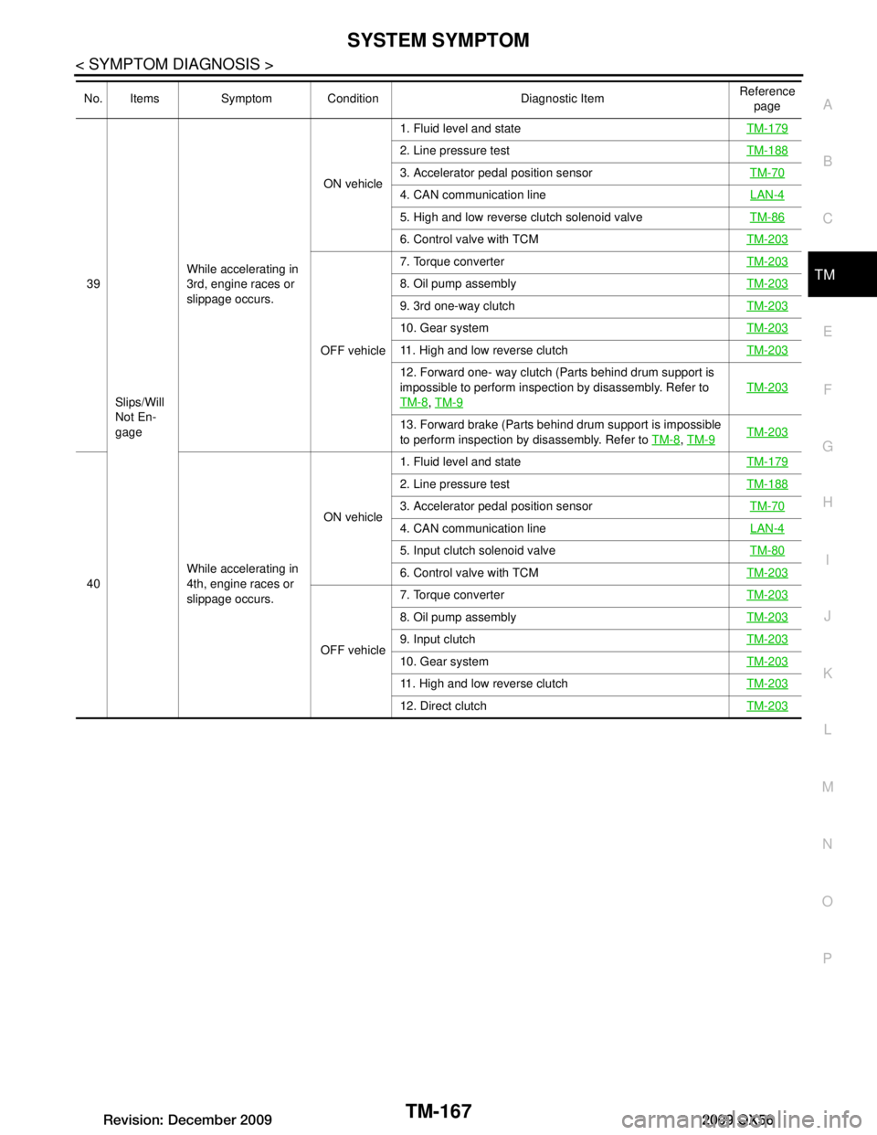
O P39
Slips/Will
Not En-
gage While accelerating in
3rd, engine races or
slippage occurs.
ON vehicle
1. Fluid level and state
TM-179
2. Line pressure testTM-188
3. Accelerator pedal position sensor TM-70
4. CAN communication line LAN-4
5. High and low reverse clutch solenoid valveTM-86
6. Control valve with TCMTM-203
OFF vehicle7. Torque converter
TM-203
8. Oil pump assemblyTM-203
9. 3rd one-way clutchTM-203
10. Gear systemTM-203
11. High and low reverse clutchTM-203
12. Forward one- way clutch (Parts behind drum support is
impossible to perform inspection by disassembly. Refer to
TM-8
, TM-9
TM-203
13. Forward brake (Parts behind drum support is impossible
to perform inspection by disassembly. Refer to TM-8
, TM-9TM-203
40 While accelerating in
4th, engine races or
slippage occurs. ON vehicle
1. Fluid level and state
TM-179
2. Line pressure testTM-188
3. Accelerator pedal position sensor TM-70
4. CAN communication line LAN-4
5. Input clutch solenoid valveTM-80
6. Control valve with TCMTM-203
OFF vehicle7. Torque converter
TM-203
8. Oil pump assemblyTM-203
9. Input clutchTM-203
10. Gear systemTM-203
11. High and low reverse clutchTM-203
12. Direct clutchTM-203
No. Items Symptom Condition Diagnostic Item Reference
page
Revision: December 20092009 QX56
Page 3816 of 4171
TM-168
< SYMPTOM DIAGNOSIS >
SYSTEM SYMPTOM
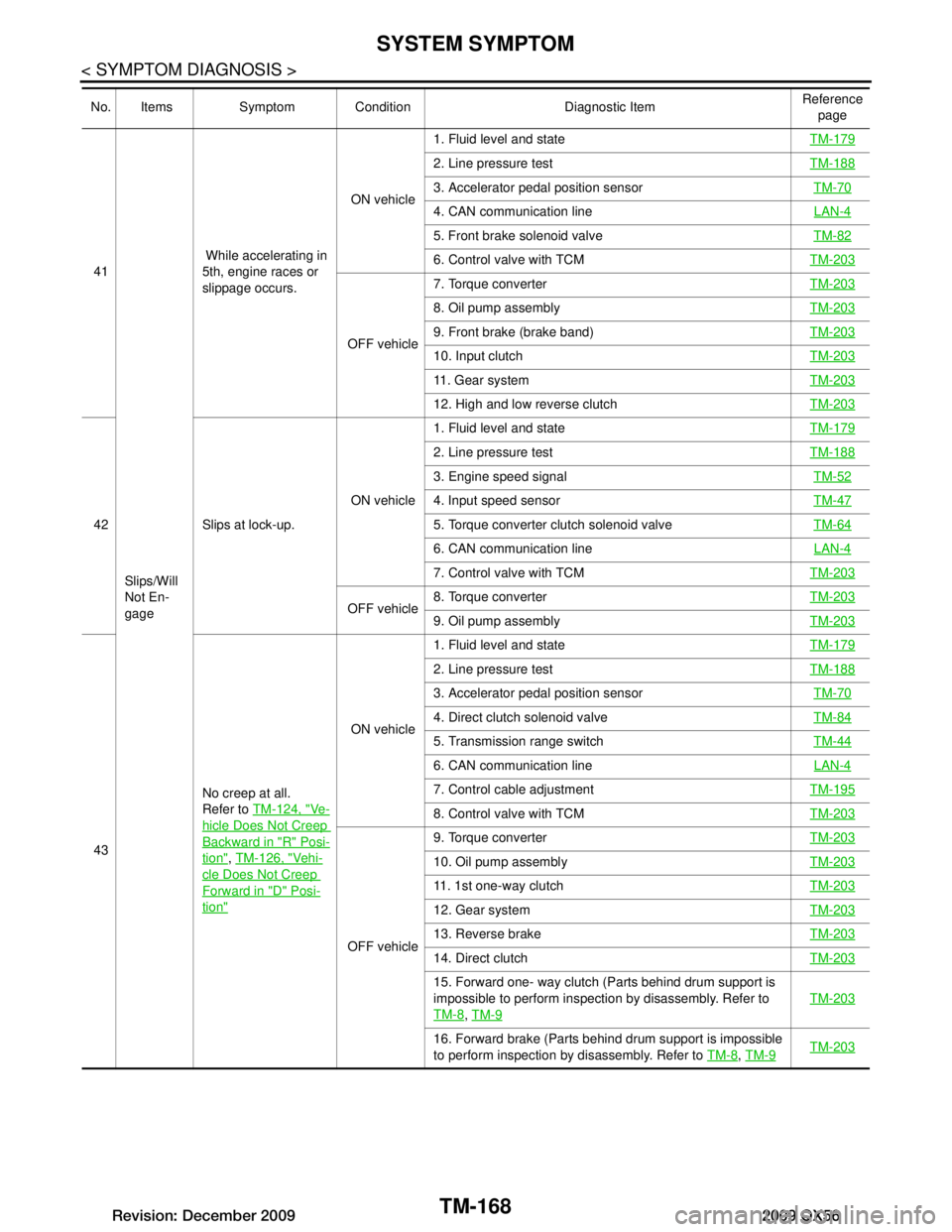
41Slips/Will
Not En-
gage While accelerating in
5th, engine races or
slippage occurs.
ON vehicle
1. Fluid level and state
TM-179
2. Line pressure testTM-188
3. Accelerator pedal position sensor TM-70
4. CAN communication line LAN-4
5. Front brake solenoid valveTM-82
6. Control valve with TCMTM-203
OFF vehicle7. Torque converter
TM-203
8. Oil pump assemblyTM-203
9. Front brake (brake band)TM-203
10. Input clutchTM-203
11. Gear systemTM-203
12. High and low reverse clutchTM-203
42 Slips at lock-up.ON vehicle1. Fluid level and state
TM-179
2. Line pressure testTM-188
3. Engine speed signal TM-52
4. Input speed sensorTM-47
5. Torque converter clutch solenoid valveTM-64
6. CAN communication line LAN-4
7. Control valve with TCMTM-203
OFF vehicle8. Torque converter
TM-2039. Oil pump assemblyTM-203
43No creep at all.
Refer to
TM-124, "Ve-
hicle Does Not Creep
Backward in "R" Posi-
tion", TM-126, "Vehi-
cle Does Not Creep
Forward in "D" Posi-
tion"
ON vehicle 1. Fluid level and state
TM-179
2. Line pressure testTM-188
3. Accelerator pedal position sensor TM-70
4. Direct clutch solenoid valveTM-84
5. Transmission range switchTM-44
6. CAN communication line LAN-4
7. Control cable adjustmentTM-195
8. Control valve with TCMTM-203
OFF vehicle9. Torque converter
TM-203
10. Oil pump assemblyTM-203
11. 1st one-way clutchTM-203
12. Gear systemTM-203
13. Reverse brakeTM-203
14. Direct clutchTM-203
15. Forward one- way clutch (Parts behind drum support is
impossible to perform inspection by disassembly. Refer to
TM-8
, TM-9
TM-203
16. Forward brake (Parts behind drum support is impossible
to perform inspection by disassembly. Refer to TM-8
, TM-9TM-203
No. Items Symptom Condition Diagnostic Item Reference
page
Revision: December 20092009 QX56
Page 3817 of 4171
SYSTEM SYMPTOMTM-169
< SYMPTOM DIAGNOSIS >
CEF
G H
I
J
K L
M A
B
TM
N
O P
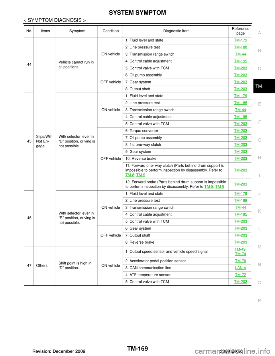
44
Slips/Will
Not En-
gage Vehicle cannot run in
all positions.
ON vehicle1. Fluid level and state
TM-179
2. Line pressure testTM-188
3. Transmission range switch TM-44
4. Control cable adjustmentTM-195
5. Control valve with TCMTM-203
OFF vehicle6. Oil pump assembly
TM-2037. Gear systemTM-203
8. Output shaftTM-203
45With selector lever in
“D” position, driving is
not possible. ON vehicle
1. Fluid level and state
TM-179
2. Line pressure testTM-188
3. Transmission range switch TM-44
4. Control cable adjustmentTM-195
5. Control valve with TCMTM-203
OFF vehicle6. Torque converter
TM-203
7. Oil pump assembly TM-203
8. 1st one-way clutchTM-203
9. Gear systemTM-203
10. Reverse brakeTM-203
11. Forward one- way clutch (Parts behind drum support is
impossible to perform inspection by disassembly. Refer to
TM-8
, TM-9
TM-203
12. Forward brake (Parts behind drum support is impossible
to perform inspection by disassembly. Refer to TM-8
, TM-9TM-203
46 With selector lever in
“R” position, driving is
not possible. ON vehicle
1. Fluid level and state
TM-179
2. Line pressure testTM-188
3. Transmission range switch TM-44
4. Control cable adjustmentTM-195
5. Control valve with TCMTM-203
OFF vehicle6. Gear system
TM-2037. Output shaftTM-203
8. Reverse brakeTM-203
47 OthersShift point is high in
“D” position. ON vehicle1. Output speed sensor and vehicle speed signal
TM-49
,
TM-74
2. Accelerator pedal position sensor TM-70
3. CAN communication line LAN-4
4. ATF temperature sensorTM-72
5. Control valve with TCMTM-203
No. Items Symptom Condition Diagnostic Item Reference
page
Revision: December 20092009 QX56
Page 3820 of 4171
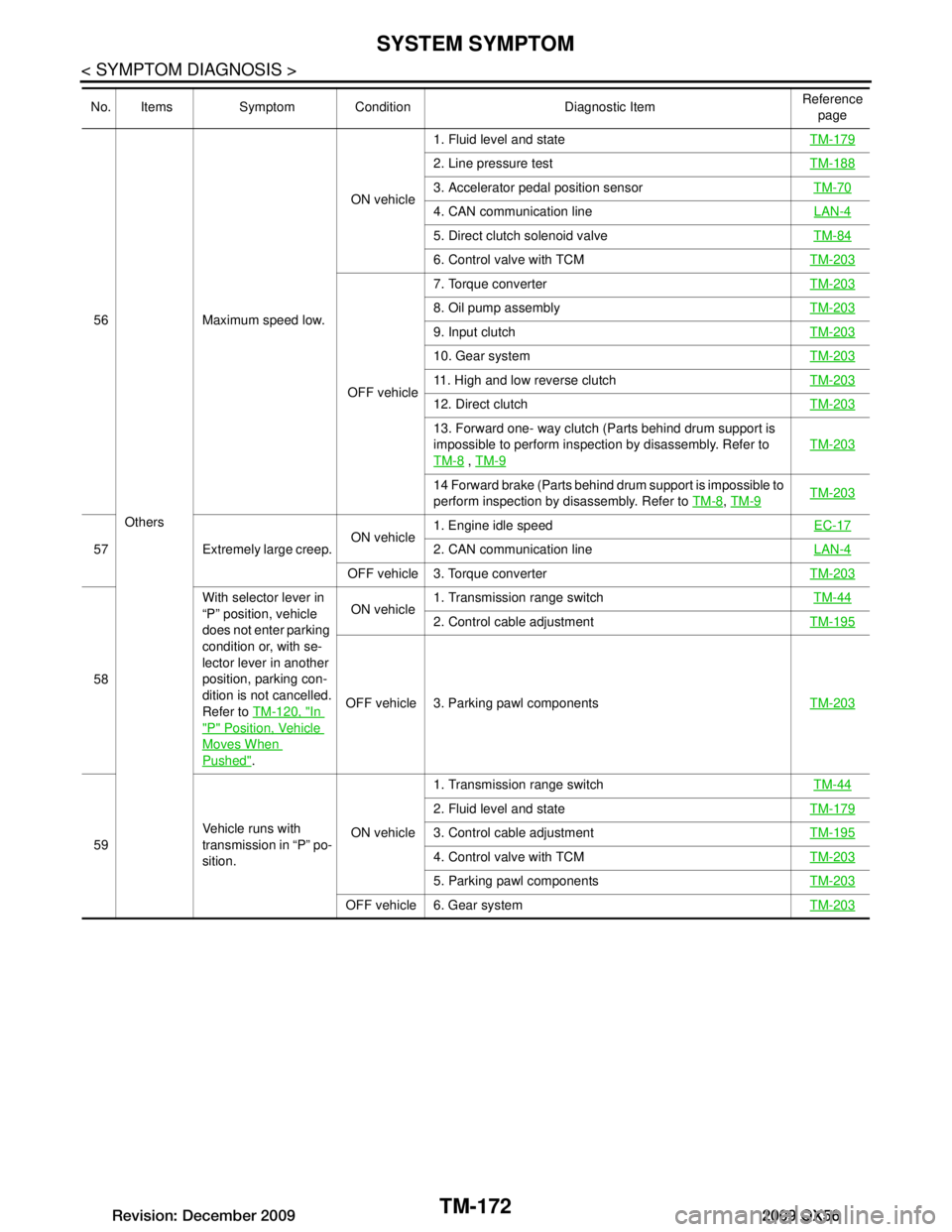
TM-172
< SYMPTOM DIAGNOSIS >
SYSTEM SYMPTOM
56Others Maximum speed low.
ON vehicle
1. Fluid level and state
TM-179
2. Line pressure testTM-188
3. Accelerator pedal position sensor TM-70
4. CAN communication line LAN-4
5. Direct clutch solenoid valveTM-84
6. Control valve with TCMTM-203
OFF vehicle7. Torque converter
TM-203
8. Oil pump assemblyTM-203
9. Input clutchTM-203
10. Gear systemTM-203
11. High and low reverse clutchTM-203
12. Direct clutchTM-203
13. Forward one- way clutch (Parts behind drum support is
impossible to perform inspection by disassembly. Refer to
TM-8
, TM-9
TM-203
14 Forward brake (Parts behind drum support is impossible to
perform inspection by disassembly. Refer to TM-8
, TM-9TM-203
57 Extremely large creep. ON vehicle1. Engine idle speed
EC-172. CAN communication lineLAN-4
OFF vehicle 3. Torque converter TM-203
58With selector lever in
“P” position, vehicle
does not enter parking
condition or, with se-
lector lever in another
position, parking con-
dition is not cancelled.
Refer to
TM-120, "In
"P" Position, Vehicle
Moves When
Pushed". ON vehicle
1. Transmission range switch
TM-44
2. Control cable adjustmentTM-195
OFF vehicle 3. Parking pawl components TM-203
59Vehicle runs with
transmission in “P” po-
sition. ON vehicle1. Transmission range switch
TM-44
2. Fluid level and stateTM-179
3. Control cable adjustmentTM-195
4. Control valve with TCMTM-203
5. Parking pawl componentsTM-203
OFF vehicle 6. Gear system TM-203
No. Items Symptom Condition Diagnostic Item Reference
page
Revision: December 20092009 QX56
Page 3825 of 4171
PREPARATIONTM-177
< PREPARATION >
CEF
G H
I
J
K L
M A
B
TM
N
O P
PREPARATION
PREPARATION
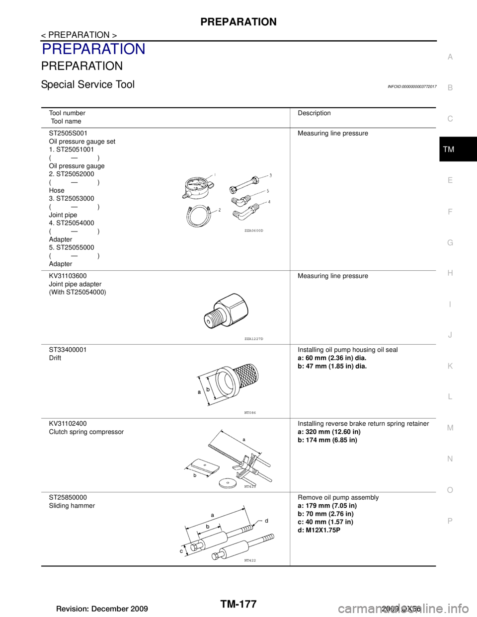
Special Service ToolINFOID:0000000003772017
Tool number
Tool name Description
ST2505S001
Oil pressure gauge set
1. ST25051001
(—)
Oil pressure gauge
2. ST25052000
(—)
Hose
3. ST25053000
(—)
Joint pipe
4. ST25054000
(—)
Adapter
5. ST25055000
(—)
Adapter Measuring line pressure
KV31103600
Joint pipe adapter
(With ST25054000) Measuring line pressure
ST33400001
Drift Installing oil pump housing oil seal
a: 60 mm (2.36 in) dia.
b: 47 mm (1.85 in) dia.
KV31102400
Clutch spring compressor Installing reverse brake
return spring retainer
a: 320 mm (12.60 in)
b: 174 mm (6.85 in)
ST25850000
Sliding hammer Remove oil pump assembly
a: 179 mm (7.05 in)
b: 70 mm (2.76 in)
c: 40 mm (1.57 in)
d: M12X1.75P
ZZA0600D
ZZA1227D
NT086
NT423
NT422
Revision: December 20092009 QX56
Page 3836 of 4171
TM-188
< ON-VEHICLE MAINTENANCE >
LINE PRESSURE TEST
LINE PRESSURE TEST
Inspection and JudgmentINFOID:0000000003772025
LINE PRESSURE TEST
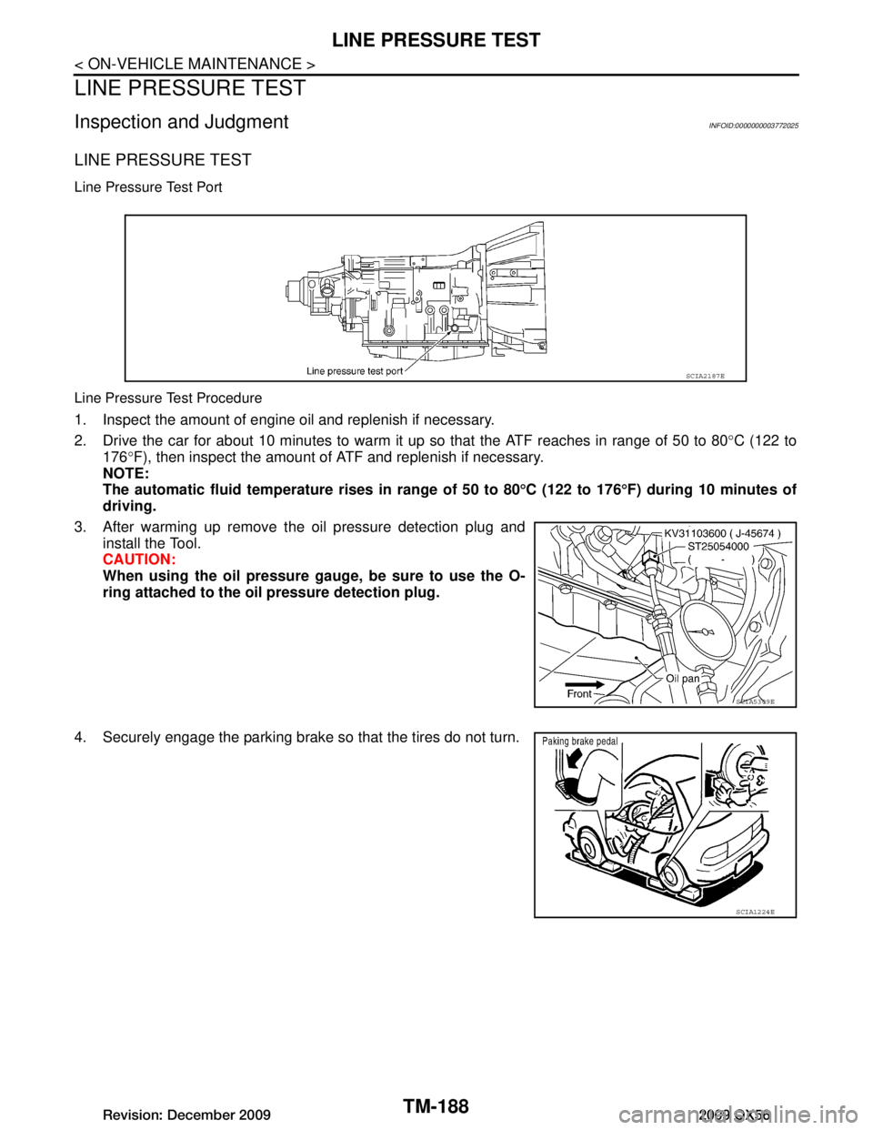
Line Pressure Test Port
Line Pressure Test Procedure
1. Inspect the amount of engine oil and replenish if necessary.
2. Drive the car for about 10 minutes to warm it up so that the ATF reaches in range of 50 to 80°C (122 to
176 °F), then inspect the amount of ATF and replenish if necessary.
NOTE:
The automatic fluid temperatur e rises in range of 50 to 80°C (122 to 176 °F) during 10 minutes of
driving.
3. After warming up remove the oil pressure detection plug and install the Tool.
CAUTION:
When using the oil pressure ga uge, be sure to use the O-
ring attached to the oi l pressure detection plug.
4. Securely engage the parking brake so that the tires do not turn.
SCIA2187E
SCIA5309E
SCIA1224E
Revision: December 20092009 QX56
Page 3837 of 4171
LINE PRESSURE TESTTM-189
< ON-VEHICLE MAINTENANCE >
CEF
G H
I
J
K L
M A
B
TM
N
O P
5. Start the engine, then measure the line pressure at both idle and the stall speed.
CAUTION:
Keep the brake pedal pressed all the way down during
measurement.
When measuring the line pressu re at the stall speed, refer
to TM-186, "Inspection and Judgment"
.
6. After the measurements are complete, install the oil pressure detection plug and tighten to the regulation torque below.
CAUTION:
Do not reuse the O-ring.
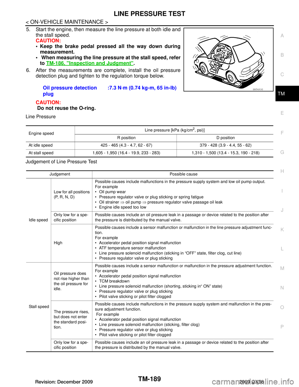
Line Pressure
Judgement of Line Pressure Test
Oil pressure detection
plug :7.3 N·m (0.74 kg-m, 65 in-lb)SAT493G
Engine speed
Line pressure [kPa (kg/cm
2, psi)]
R position D position
At idle speed 425 - 465 (4.3 - 4.7, 62 - 67) 379 - 428 (3.9 - 4.4, 55 - 62)
At stall speed 1,605 - 1,950 (16.4 - 19.9, 233 - 283) 1,310 - 1,500 (13.4 - 15.3, 190 - 218)
Judgement Possible cause
Idle speed Low for all positions
(P, R, N, D)
Possible causes include malfunctions in the pressure supply system and low oil pump output.
For example
Oil pump wear
Pressure regulator valve or plug sticking or spring fatigue
Oil strainer
⇒ oil pump ⇒ pressure regulator valve passage oil leak
Engine idle speed too low
Only low for a spe-
cific position Possible causes include an oil pressure leak in a passage or device related to the position after
the pressure is distributed by the manual valve.
High Possible causes include a sensor malfunction or malfunction in the line pressure adjustment func-
tion.
For example
Accelerator pedal position signal malfunction
ATF temperature sensor malfunction
Line pressure solenoid malfunction (sticking in “OFF” state, filter clog, cut line)
Pressure regulator valve or plug sticking
Stall speed Oil pressure does
not rise higher than
the oil pressure for
idle.
Possible causes include a sensor malfunction or malfunction in the pressure adjustment function.
For example
Accelerator pedal position signal malfunction
TCM breakdown
Line pressure solenoid malfunction (shorting, sticking in“ ON” state)
Pressure regulator valve or plug sticking
Pilot valve sticking or pilot filter clogged
The pressure rises,
but does not enter
the standard posi-
tion. Possible causes include malfunctions in the pressure supply system and malfunction in the pres-
sure adjustment function.
For example
Accelerator pedal position signal malfunction
Line pressure solenoid malfunction (sticking, filter clog)
Pressure regulator valve or plug sticking
Pilot valve sticking or pilot filter clogged
Only low for a spe-
cific position Possible causes include an oil pressure leak in a passage or device related to the position after
the pressure is distributed by the manual valve.
Revision: December 20092009 QX56