Page 2664 of 4171
ENGINE OILLU-9
< ON-VEHICLE MAINTENANCE >
C
DE
F
G H
I
J
K L
M A
LU
NP
O
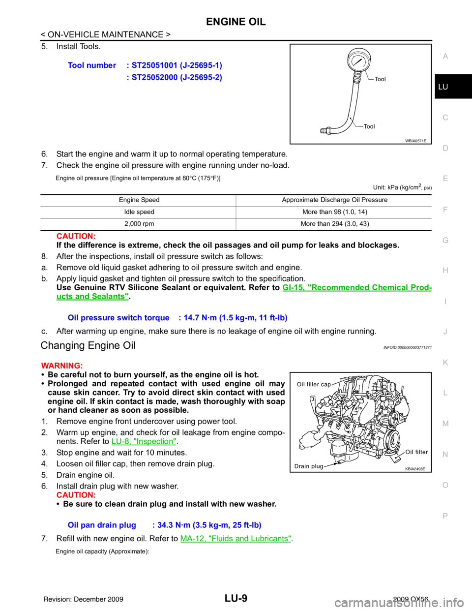
5. Install Tools.
6. Start the engine and warm it up to normal operating temperature.
7. Check the engine oil pressure with engine running under no-load.
Engine oil pressure [Engine oil temperature at 80
°C (175 °F)]
Unit: kPa (kg/cm2, psi)
CAUTION:
If the difference is extreme, check the oil passages and oil pump for leaks and blockages.
8. After the inspections, install oil pressure switch as follows:
a. Remove old liquid gasket adhering to oil pressure switch and engine.
b. Apply liquid gasket and tighten oil pressure switch to the specification. Use Genuine RTV Silicone Seal ant or equivalent. Refer to GI-15, "
Recommended Chemical Prod-
ucts and Sealants".
c. After warming up engine, make sure there is no leakage of engine oil with engine running.
Changing Engine OilINFOID:0000000003771271
WARNING:
• Be careful not to burn yourself, as the engine oil is hot.
• Prolonged and repeated contact with used engine oil may cause skin cancer. Try to avoid direct skin contact with used
engine oil. If skin contact is made, wash thoroughly with soap
or hand cleaner as soon as possible.
1. Remove engine front undercover using power tool.
2. Warm up engine, and check for oil leakage from engine compo- nents. Refer to LU-8, "
Inspection".
3. Stop engine and wait for 10 minutes.
4. Loosen oil filler cap, then remove drain plug.
5. Drain engine oil.
6. Install drain plug with new washer. CAUTION:
• Be sure to clean drain plug and install with new washer.
7. Refill with new engine oil. Refer to MA-12, "
Fluids and Lubricants".
Engine oil capacity (Approximate):
Tool number : ST25051001 (J-25695-1)
: ST25052000 (J-25695-2)
WBIA0571E
Engine Speed Approximate Discharge Oil Pressure
Idle speed More than 98 (1.0, 14)
2,000 rpm More than 294 (3.0, 43)
Oil pressure switch torque : 14.7 N·m (1.5 kg-m, 11 ft-lb)
Oil pan drain plug : 34.3 N·m (3.5 kg-m, 25 ft-lb)
KBIA2498E
Revision: December 20092009 QX56
Page 2666 of 4171
OIL FILTERLU-11
< ON-VEHICLE MAINTENANCE >
C
DE
F
G H
I
J
K L
M A
LU
NP
O
OIL FILTER
Removal and InstallationINFOID:0000000003771272
REMOVAL
1. Drain the engine oil. Refer to
LU-9, "Changing Engine Oil".
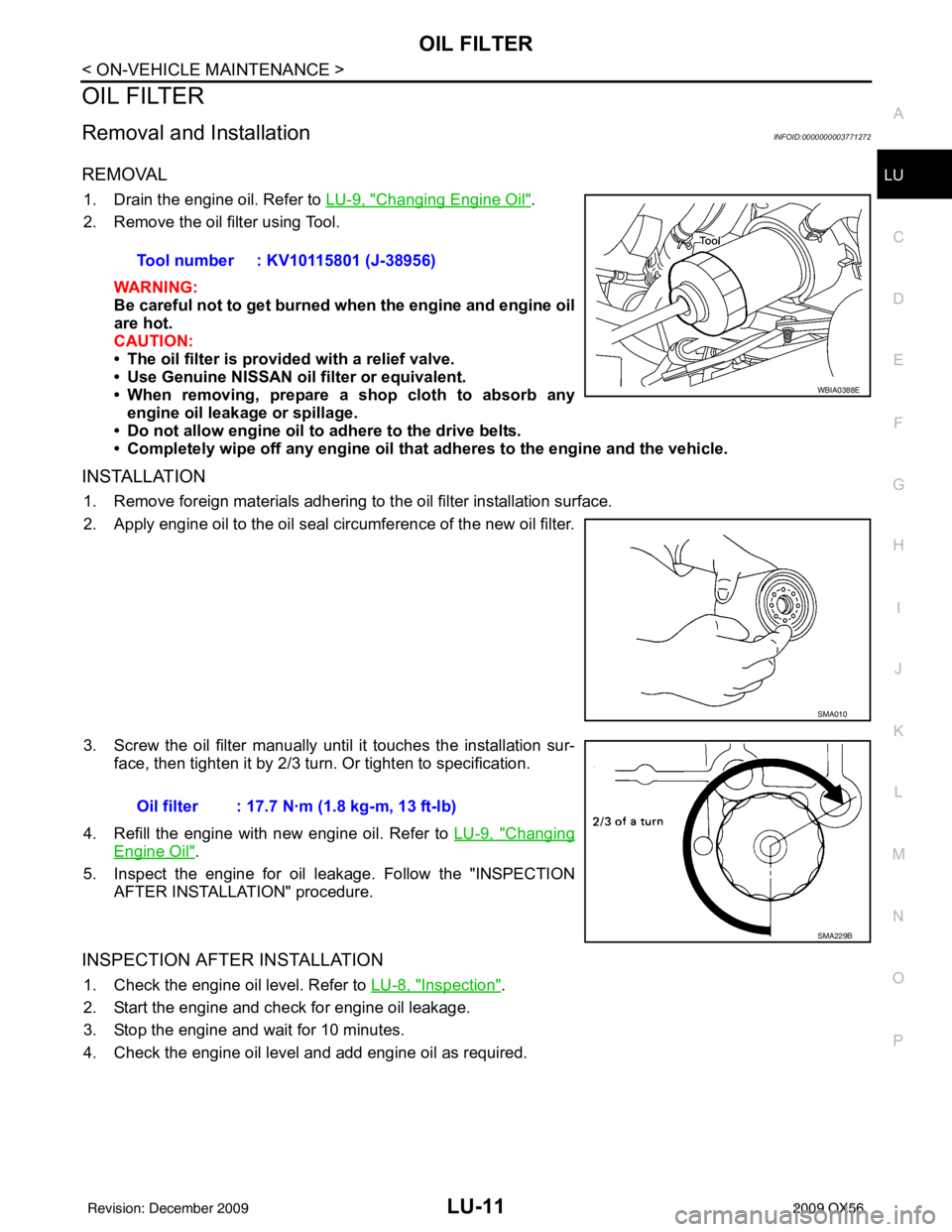
2. Remove the oil filter using Tool.
WARNING:
Be careful not to get burned when the engine and engine oil
are hot.
CAUTION:
• The oil filter is provided with a relief valve.
• Use Genuine NISSAN oil filter or equivalent.
• When removing, prepare a s hop cloth to absorb any
engine oil leakage or spillage.
• Do not allow engine oil to adhere to the drive belts.
• Completely wipe off any engine oil that adheres to the engine and the vehicle.
INSTALLATION
1. Remove foreign materials adhering to the oil filter installation surface.
2. Apply engine oil to the oil seal circumference of the new oil filter.
3. Screw the oil filter manually until it touches the installation sur-
face, then tighten it by 2/3 turn. Or tighten to specification.
4. Refill the engine with new engine oil. Refer to LU-9, "
Changing
Engine Oil".
5. Inspect the engine for oil leakage. Follow the "INSPECTION AFTER INSTALLATION" procedure.
INSPECTION AFTER INSTALLATION
1. Check the engine oil level. Refer to LU-8, "Inspection".
2. Start the engine and check for engine oil leakage.
3. Stop the engine and wait for 10 minutes.
4. Check the engine oil level and add engine oil as required. Tool number : KV10115801 (J-38956)
WBIA0388E
SMA010
Oil filter : 17.7 N·m (1.8 kg-m, 13 ft-lb)
SMA229B
Revision: December 20092009 QX56
Page 2668 of 4171
OIL COOLERLU-13
< ON-VEHICLE REPAIR >
C
DE
F
G H
I
J
K L
M A
LU
NP
O
Relief Valve
Inspect relief valve for movement, cracks and breaks by
pushing the ball. If replacement is necessary, remove
the valve by prying it out using a suitable tool. Install a new valve in place by tapping it.
INSTALLATION
Installation is in the reverse order of removal, paying attention to the following:
• Confirm that no foreign objects are adhering to the sealing sur- faces of the oil cooler or oil pan.
• Tighten the connecting bolt after aligning the stopper on the oil pan side with protrusion of the oil cooler.
INSPECTION AFTER INSTALLATION
1. Check levels and add engine oil and engine coolant. Refer to LU-8, "Inspection" and CO-10, "Inspection".
2. Start the engine, and check for leaks of engine oil and engine coolant.
3. Stop the engine and wait for 10 minutes.
4. Check engine oil level and engine coolant level again.
KBIA2500E
Revision: December 20092009 QX56
Page 2670 of 4171
OIL PUMPLU-15
< ON-VEHICLE REPAIR >
C
DE
F
G H
I
J
K L
M A
LU
NP
O
INSPECTION AFTER INSTALLATION
• Start the engine, and check for leaks of engine oil.
• Stop engine and wait 10 minutes.
• Check level and add engine oil as required. Refer to
LU-8
.
Revision: December 20092009 QX56
Page 2692 of 4171
ENGINE MAINTENANCEMA-19
< ON-VEHICLE MAINTENANCE >
C
DE
F
G H
I
J
K L
M B
MA
N
O A
• When removing, prepare a shop cloth to ab
sorb any engine oil leakage or spillage.
• Do not allow engine oil to adhere to the drive belts.
• Completely wipe off any engine oil that adheres to the engine and the vehicle.
INSTALLATION
1. Remove foreign materials adhering to the oil filter installation surface.
2. Apply engine oil to the oil seal circumference of the new oil filter.
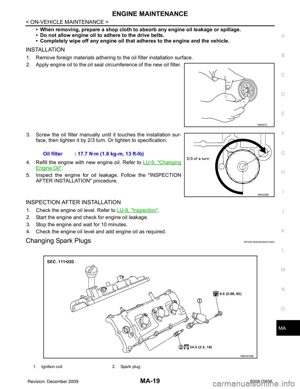
3. Screw the oil filter manually until it touches the installation sur-
face, then tighten it by 2/3 turn. Or tighten to specification.
4. Refill the engine with new engine oil. Refer to LU-9, "
Changing
Engine Oil".
5. Inspect the engine for oil leakage. Follow the "INSPECTION AFTER INSTALLATION" procedure.
INSPECTION AFTER INSTALLATION
1. Check the engine oil level. Refer to LU-8, "Inspection".
2. Start the engine and check for engine oil leakage.
3. Stop the engine and wait for 10 minutes.
4. Check the engine oil level and add engine oil as required.
Changing Spark PlugsINFOID:0000000004215530
SMA010
Oil filter : 17.7 N·m (1.8 kg-m, 13 ft-lb)
SMA229B
1. Ignition coil 2. Spark plug
WBIA0796E
Revision: December 20092009 QX56
Page 2699 of 4171
MA-26
< ON-VEHICLE MAINTENANCE >
CHASSIS AND BODY MAINTENANCE
Changing Transfer Fluid
INFOID:0000000004215546
CAUTION:
If using the vehicle for towing, the transfer fluid must be replaced as specified. Refer to MA-8, "
Intro-
duction of Periodic Maintenance".
DRAINING
1. Stop engine.
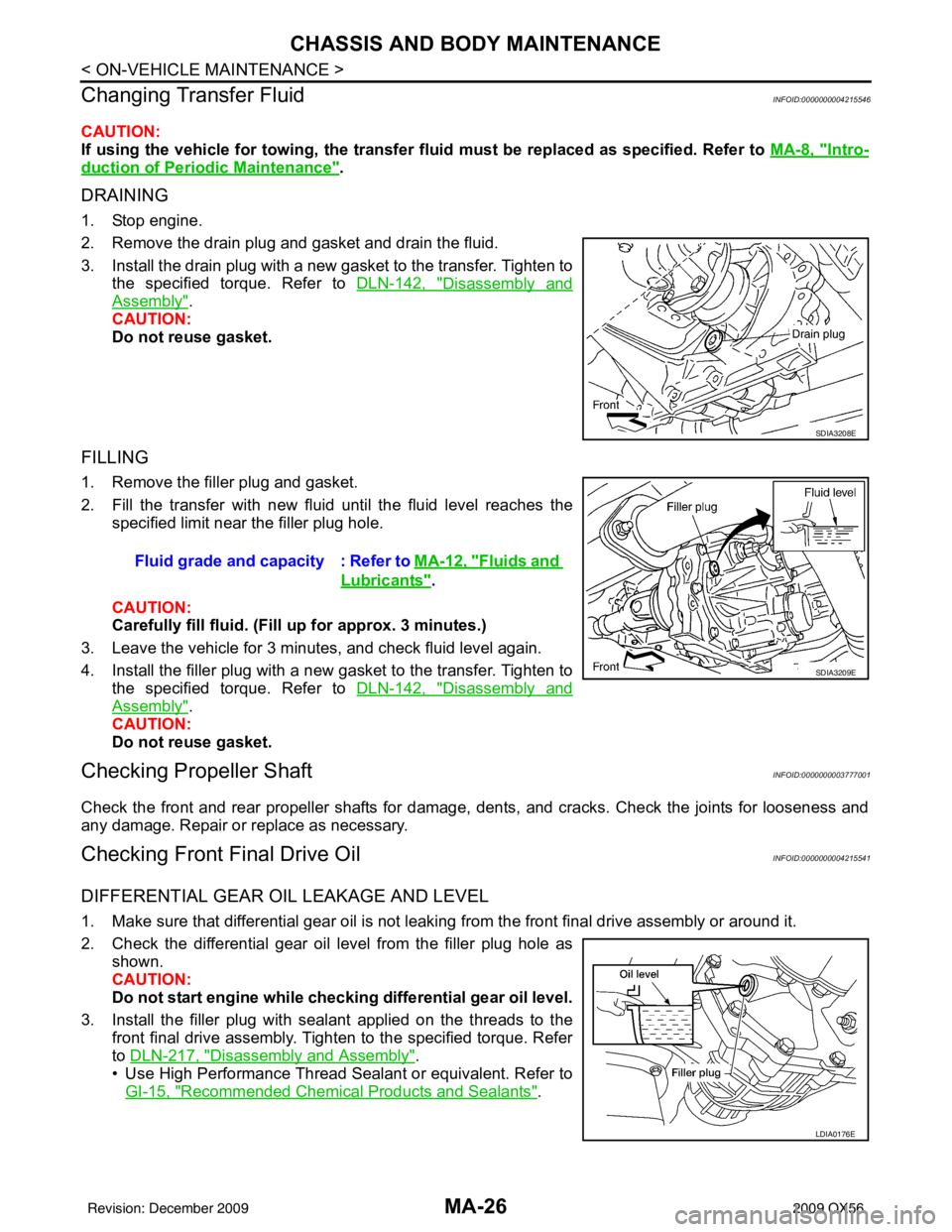
2. Remove the drain plug and gasket and drain the fluid.
3. Install the drain plug with a new gasket to the transfer. Tighten to
the specified torque. Refer to DLN-142, "
Disassembly and
Assembly".
CAUTION:
Do not reuse gasket.
FILLING
1. Remove the filler plug and gasket.
2. Fill the transfer with new fluid until the fluid level reaches the specified limit near the filler plug hole.
CAUTION:
Carefully fill fluid. (Fil l up for approx. 3 minutes.)
3. Leave the vehicle for 3 minutes, and check fluid level again.
4. Install the filler plug with a new gasket to the transfer. Tighten to the specified torque. Refer to DLN-142, "
Disassembly and
Assembly".
CAUTION:
Do not reuse gasket.
Checking Propeller ShaftINFOID:0000000003777001
Check the front and rear propeller shafts for damage, dents, and cracks. Check the joints for looseness and
any damage. Repair or replace as necessary.
Checking Front Final Drive OilINFOID:0000000004215541
DIFFERENTIAL GEAR OIL LEAKAGE AND LEVEL
1. Make sure that differential gear oil is not leaki ng from the front final drive assembly or around it.
2. Check the differential gear oil level from the filler plug hole as shown.
CAUTION:
Do not start engine while checki ng differential gear oil level.
3. Install the filler plug with sealant applied on the threads to the front final drive assembly. Tighten to the specified torque. Refer
to DLN-217, "
Disassembly and Assembly".
• Use High Performance Thread Sealant or equivalent. Refer to GI-15, "
Recommended Chemical Products and Sealants".
SDIA3208E
Fluid grade and capacity : Refer to MA-12, "Fluids and
Lubricants".
SDIA3209E
LDIA0176E
Revision: December 20092009 QX56
Page 2700 of 4171
CHASSIS AND BODY MAINTENANCEMA-27
< ON-VEHICLE MAINTENANCE >
C
DE
F
G H
I
J
K L
M B
MA
N
O A
Changing Front Final Drive OilINFOID:0000000004215542
DRAINING
1. Stop the engine.
2. Remove the drain plug from the front final drive assembly to drain the differential gear oil.
3. Install the drain plug with sealant applied on the thr
eads to the front final drive assembly. Tighten to the
specified torque. Refer to DLN-217, "
Disassembly and Assembly".
• Use High Performance Thread Sealant or equivalent. Refer to GI-15, "
Recommended Chemical Prod-
ucts and Sealants".
FILLING
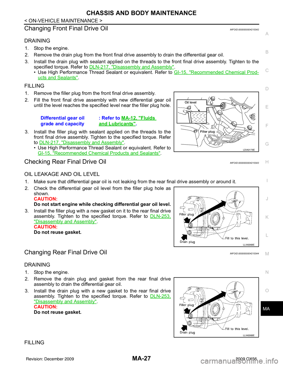
1. Remove the filler plug from the front final drive assembly.
2. Fill the front final drive assembly with new differential gear oil
until the level reaches the specified level near the filler plug hole.
3. Install the filler plug with sealant applied on the threads to the front final drive assembly. Tighten to the specified torque. Refer
to DLN-217, "
Disassembly and Assembly".
• Use High Performance Thread Sealant or equivalent. Refer to
GI-15, "
Recommended Chemical Products and Sealants".
Checking Rear Final Drive OilINFOID:0000000004215543
OIL LEAKAGE AND OIL LEVEL
1. Make sure that differential gear oil is not leaking from the rear final drive assembly or around it.
2. Check the differential gear oil level from the filler plug hole as shown.
CAUTION:
Do not start engine while checki ng differential gear oil level.
3. Install the filler plug with a new gasket on it to the rear final drive assembly. Tighten to the specified torque. Refer to DLN-253,
"Disassembly and Assembly".
CAUTION:
Do not reuse gasket.
Changing Rear Final Drive OilINFOID:0000000004215544
DRAINING
1. Stop the engine.
2. Remove the drain plug and gasket from the rear final drive assembly to drain the differential gear oil.
3. Install the drain plug with a new gasket to the rear final drive assembly. Tighten to the specified torque. Refer to DLN-253,
"Disassembly and Assembly".
CAUTION:
Do not reuse gasket.
FILLING
Differential gear oil
grade and capacity : Refer to
MA-12, "Fluids
and Lubricants".
LDIA0176E
LLIA0068E
LLIA0068E
Revision: December 20092009 QX56
Page 2764 of 4171
MWI-42
< ECU DIAGNOSIS >
COMBINATION METER
ECU DIAGNOSIS
COMBINATION METER
Reference ValueINFOID:0000000003776653
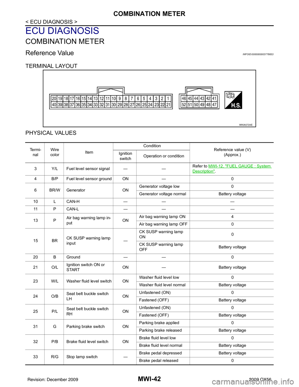
TERMINAL LAYOUT
PHYSICAL VALUES
WKIA5724E
Te r m i -nal Wire
color Item Condition
Reference value (V)
(Approx.)
Ignition
switch Operation or condition
3 Y/L Fuel level sensor signal — —Refer to MWI-12, "
FUEL GAUGE : System
Description".
4 B/P Fuel level sensor ground ON —0
6 BR/W Generator ONGenerator voltage low
0
Generator voltage normal Battery voltage
10 L CAN-H —— —
11 P C A N - L —— —
13 P Air bag warning lamp in-
put ONAir bag warning lamp ON
4
Air bag warning lamp OFF 0
15 BR CK SUSP warning lamp
input —CK SUSP warning lamp
ON
0
CK SUSP warning lamp
OFF Battery voltage
20 B Ground —— 0
21 O/L Ignition switch ON or
START ON
— Battery voltage
23 W/L Washer fluid level switch ON Washer fluid level low
0
Washer fluid level normal Battery voltage
24 O/B Seat belt buckle switch
LH ONUnfastened (ON)
0
Fastened (OFF) Battery voltage
25 P/L Seat belt buckle switch
RH ONUnfastened (ON)
0
Fastened (OFF) Battery voltage
31 G Parking brake switch ON Parking brake applied
0
Parking brake released Battery voltage
32 P/B Brake fluid level switch ON Brake fluid level low
0
Brake fluid level normal Battery voltage
33 R/G Stop lamp switch —Brake pedal depressed
Battery voltage
Brake pedal released 0
Revision: December 20092009 QX56