Page 4034 of 4171
WCS
BCM (BODY CONTROL MODULE)WCS-57
< ECU DIAGNOSIS >
C
DE
F
G H
I
J
K L
M B A
O P
Wiring DiagramINFOID:0000000004115467
AAMWA0236GB
Revision: December 20092009 QX56
Page 4035 of 4171
WCS-58
< ECU DIAGNOSIS >
BCM (BODY CONTROL MODULE)
ABMWA0015GB
Revision: December 20092009 QX56
Page 4036 of 4171
WCS
BCM (BODY CONTROL MODULE)WCS-59
< ECU DIAGNOSIS >
C
DE
F
G H
I
J
K L
M B A
O P
AAMWA0237GB
Revision: December 20092009 QX56
Page 4037 of 4171
WCS-60
< ECU DIAGNOSIS >
BCM (BODY CONTROL MODULE)
ABMIA0023GB
Revision: December 20092009 QX56
Page 4038 of 4171
WCS
BCM (BODY CONTROL MODULE)WCS-61
< ECU DIAGNOSIS >
C
DE
F
G H
I
J
K L
M B A
O P
ABMIA0024GB
Revision: December 20092009 QX56
Page 4043 of 4171

WT-1
SUSPENSION
C
DF
G H
I
J
K L
M
SECTION WT
A
B
WT
N
O PCONTENTS
ROAD WHEELS & TIRES
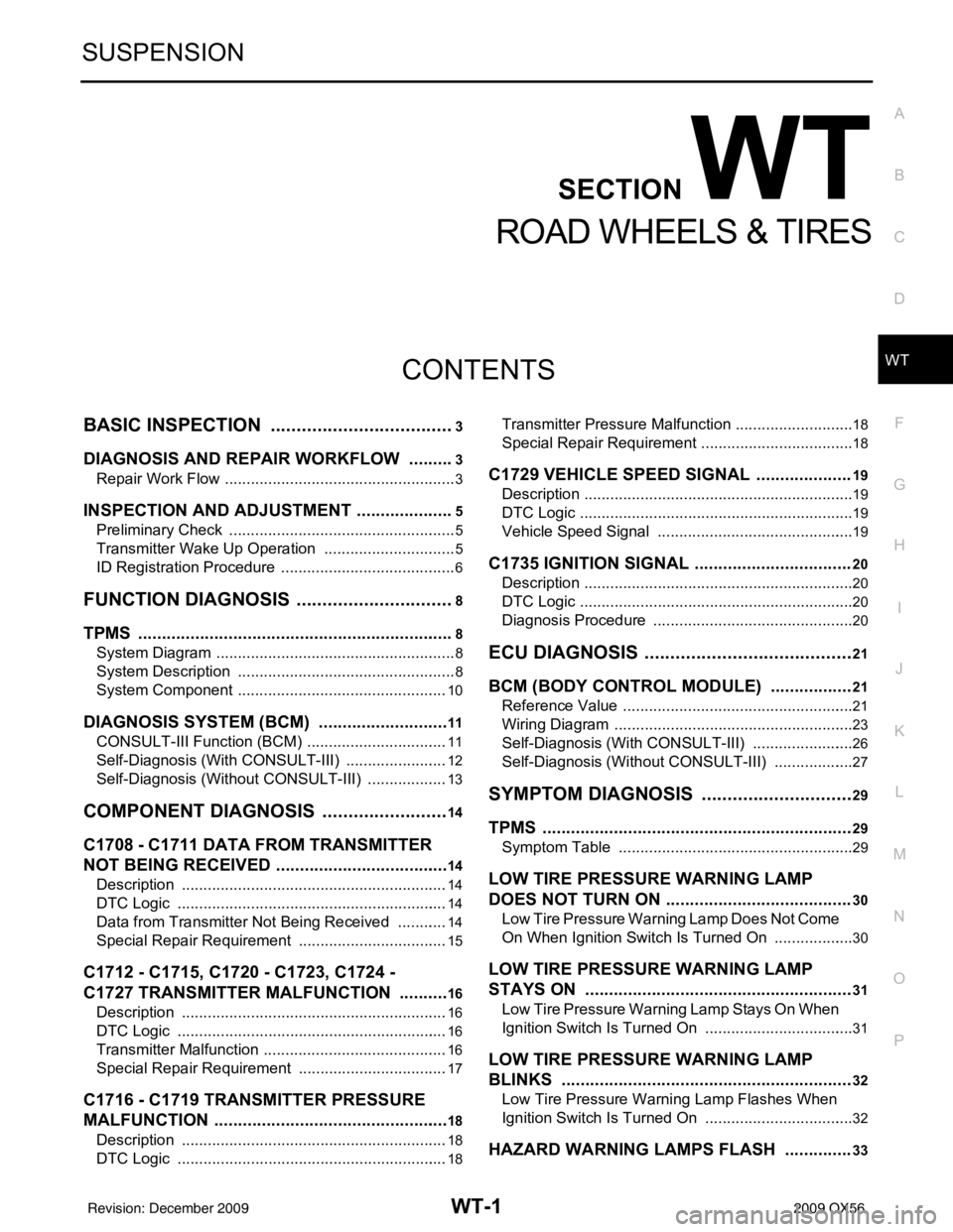
BASIC INSPECTION ....... .............................3
DIAGNOSIS AND REPAIR WORKFLOW ..... .....3
Repair Work Flow ................................................ ......3
INSPECTION AND ADJUSTMENT .....................5
Preliminary Check ............................................... ......5
Transmitter Wake Up Operation ...............................5
ID Registration Procedure .........................................6
FUNCTION DIAGNOSIS ...............................8
TPMS .............................................................. .....8
System Diagram .................................................. ......8
System Description ...................................................8
System Component .................................................10
DIAGNOSIS SYSTEM (BCM) ............................11
CONSULT-III Function (BCM) ............................. ....11
Self-Diagnosis (With CONSULT-III) ........................12
Self-Diagnosis (Without CONSULT-III) ...................13
COMPONENT DIAGNOSIS .........................14
C1708 - C1711 DATA FROM TRANSMITTER
NOT BEING RECEIVED ................................. ....
14
Description .......................................................... ....14
DTC Logic ...............................................................14
Data from Transmitter Not Being Received ............14
Special Repair Requirement ...................................15
C1712 - C1715, C1720 - C1723, C1724 -
C1727 TRANSMITTER MALFUNCTION ....... ....
16
Description .......................................................... ....16
DTC Logic ...............................................................16
Transmitter Malfunction ...........................................16
Special Repair Requirement ...................................17
C1716 - C1719 TRANSMITTER PRESSURE
MALFUNCTION .............................................. ....
18
Description .......................................................... ....18
DTC Logic ...............................................................18
Transmitter Pressure Malfunction ............................18
Special Repair Requirement ................................ ....18
C1729 VEHICLE SPEED SIGNAL ....................19
Description ...............................................................19
DTC Logic ................................................................19
Vehicle Speed Signal ..............................................19
C1735 IGNITION SIGNAL .................................20
Description ...............................................................20
DTC Logic ................................................................20
Diagnosis Procedure ...............................................20
ECU DIAGNOSIS .........................................21
BCM (BODY CONTROL MODULE) .................21
Reference Value .................................................. ....21
Wiring Diagram ........................................................23
Self-Diagnosis (With CONSULT-III) ........................26
Self-Diagnosis (Without CONSULT-III) ...................27
SYMPTOM DIAGNOSIS ..............................29
TPMS .................................................................29
Symptom Table ................................................... ....29
LOW TIRE PRESSURE WARNING LAMP
DOES NOT TURN ON .......................................
30
Low Tire Pressure Warning Lamp Does Not Come
On When Ignition Switch Is Turned On ...................
30
LOW TIRE PRESSURE WARNING LAMP
STAYS ON ........................................................
31
Low Tire Pressure Warning Lamp Stays On When
Ignition Switch Is Turned On ............................... ....
31
LOW TIRE PRESSURE WARNING LAMP
BLINKS .............................................................
32
Low Tire Pressure Warning Lamp Flashes When
Ignition Switch Is Turned On ...................................
32
HAZARD WARNING LAMPS FLASH ..............33
Revision: December 20092009 QX56
Page 4053 of 4171

DIAGNOSIS SYSTEM (BCM)WT-11
< FUNCTION DIAGNOSIS >
C
DF
G H
I
J
K L
M A
B
WT
N
O P
DIAGNOSIS SYSTEM (BCM)
CONSULT-III Function (BCM)INFOID:0000000003772370
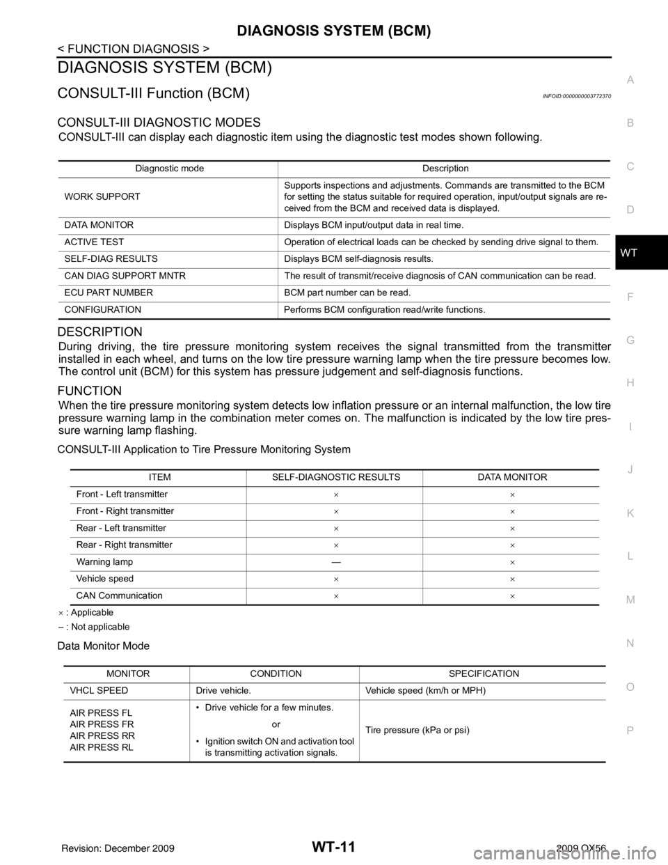
CONSULT-III DIAGNOSTIC MODES
CONSULT-III can display each diagnostic item using the diagnostic test modes shown following.
DESCRIPTION
During driving, the tire pressure monitoring system receives the signal transmitted from the transmitter
installed in each wheel, and turns on the low tire pressure warning lamp when the tire pressure becomes low.
The control unit (BCM) for this system has pr essure judgement and self-diagnosis functions.
FUNCTION
When the tire pressure monitoring system detects low infl ation pressure or an internal malfunction, the low tire
pressure warning lamp in the combination meter comes on. The malfunction is indicated by the low tire pres-
sure warning lamp flashing.
CONSULT-III Application to Ti re Pressure Monitoring System
× : Applicable
– : Not applicable
Data Monitor Mode
Diagnostic mode Description
WORK SUPPORT Supports inspections and adjustments. Commands are transmitted to the BCM
for setting the status suitable for required operation, input/output signals are re-
ceived from the BCM and received data is displayed.
DATA MONITOR Displays BCM input/output data in real time.
ACTIVE TEST Operation of electrical loads can be checked by sending drive signal to them.
SELF-DIAG RESULTS Displays BCM self-diagnosis results.
CAN DIAG SUPPORT MNTR The result of transmit/receive diagnosis of CAN communication can be read.
ECU PART NUMBER BCM part number can be read.
CONFIGURATION Performs BCM configuration read/write functions.
ITEMSELF-DIAGNOSTIC RESULTS DATA MONITOR
Front - Left transmitter ××
Front - Right transmitter ××
Rear - Left transmitter ××
Rear - Right transmitter ××
Warning lamp —×
Vehicle speed ××
CAN Communication ××
MONITORCONDITION SPECIFICATION
VHCL SPEED Drive vehicle. Vehicle speed (km/h or MPH)
AIR PRESS FL
AIR PRESS FR
AIR PRESS RR
AIR PRESS RL • Drive vehicle for a few minutes.
Tire pressure (kPa or psi)
or
• Ignition switch ON and activation tool is transmitting activation signals.
Revision: December 20092009 QX56
Page 4063 of 4171

BCM (BODY CONTROL MODULE)WT-21
< ECU DIAGNOSIS >
C
DF
G H
I
J
K L
M A
B
WT
N
O P
ECU DIAGNOSIS
BCM (BODY CONTROL MODULE)
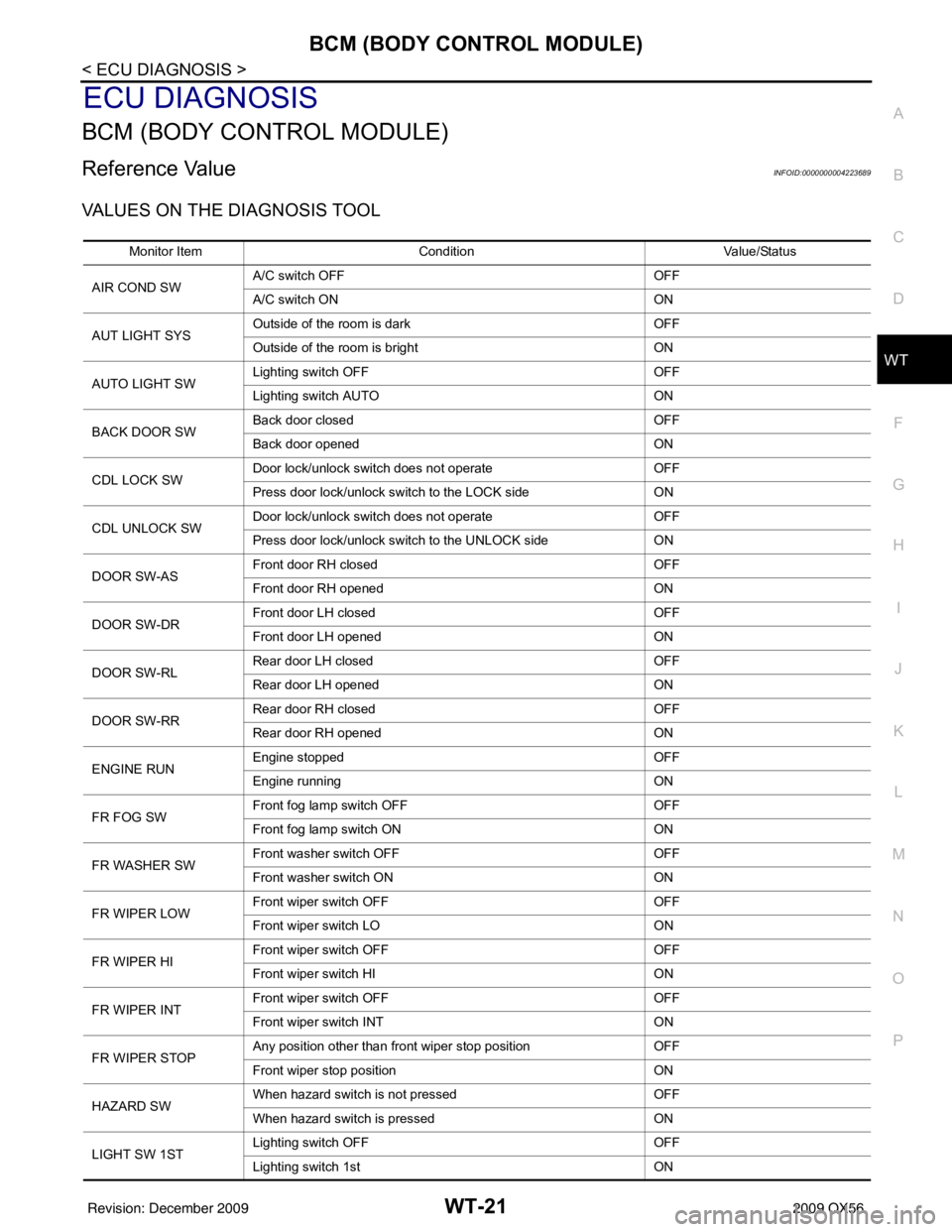
Reference ValueINFOID:0000000004223689
VALUES ON THE DIAGNOSIS TOOL
Monitor Item Condition Value/Status
AIR COND SW A/C switch OFF
OFF
A/C switch ON ON
AUT LIGHT SYS Outside of the room is dark
OFF
Outside of the room is bright ON
AUTO LIGHT SW Lighting switch OFF
OFF
Lighting switch AUTO ON
BACK DOOR SW Back door closed
OFF
Back door opened ON
CDL LOCK SW Door lock/unlock switch does not operate
OFF
Press door lock/unlock switch to the LOCK side ON
CDL UNLOCK SW Door lock/unlock switch does not operate
OFF
Press door lock/unlock switch to the UNLOCK side ON
DOOR SW-AS Front door RH closed
OFF
Front door RH opened ON
DOOR SW-DR Front door LH closed
OFF
Front door LH opened ON
DOOR SW-RL Rear door LH closed
OFF
Rear door LH opened ON
DOOR SW-RR Rear door RH closed
OFF
Rear door RH opened ON
ENGINE RUN Engine stopped
OFF
Engine running ON
FR FOG SW Front fog lamp switch OFF
OFF
Front fog lamp switch ON ON
FR WASHER SW Front washer switch OFF
OFF
Front washer switch ON ON
FR WIPER LOW Front wiper switch OFF
OFF
Front wiper switch LO ON
FR WIPER HI Front wiper switch OFF
OFF
Front wiper switch HI ON
FR WIPER INT Front wiper switch OFF
OFF
Front wiper switch INT ON
FR WIPER STOP Any position other than front wiper stop position
OFF
Front wiper stop position ON
HAZARD SW When hazard switch is not pressed
OFF
When hazard switch is pressed ON
LIGHT SW 1ST Lighting switch OFF
OFF
Lighting switch 1st ON
Revision: December 20092009 QX56