2009 INFINITI QX56 coolant
[x] Cancel search: coolantPage 1828 of 4171
PRECAUTIONSEM-5
< PRECAUTION >
C
DE
F
G H
I
J
K L
M A
EM
NP
O
Precaution for Liquid GasketINFOID:0000000005885856
REMOVAL OF LIQUID GASKET SEALING
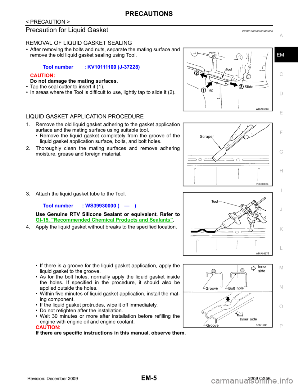
• After removing the bolts and nuts, separate the mating surface and
remove the old liquid gasket sealing using Tool.
CAUTION:
Do not damage the mating surfaces.
• Tap the seal cutter to insert it (1).
• In areas where the Tool is difficult to use, lightly tap to slide it (2).
LIQUID GASKET APPLICATION PROCEDURE
1. Remove the old liquid gasket adhering to the gasket application surface and the mating surface using suitable tool.
• Remove the liquid gasket completely from the groove of the
liquid gasket application surface, bolts, and bolt holes.
2. Thoroughly clean the mating surfaces and remove adhering moisture, grease and foreign material.
3. Attach the liquid gasket tube to the Tool. Use Genuine RTV Silicone Sealant or equivalent. Refer to
GI-15, "
Recommended Chemical Products and Sealants".
4. Apply the liquid gasket without breaks to the specified location.
• If there is a groove for the liquid gasket application, apply theliquid gasket to the groove.
• As for the bolt holes, normally apply the liquid gasket inside
the holes. If specified in the procedure, it should also be
applied outside the holes.
• Within five minutes of liquid gasket application, install the mat-
ing component.
• If the liquid gasket protrudes, wipe it off immediately.
• Do not retighten after the installation.
• Wait 30 minutes or more after installation before refilling the engine with engine oil and engine coolant.
CAUTION:
If there are specific instructions in this manual, observe them.
Tool number : KV10111100 (J-37228)
WBIA0566E
PBIC0003E
Tool number : WS39930000 ( — )
WBIA0567E
SEM159F
Revision: December 20092009 QX56
Page 1849 of 4171
EM-26
< ON-VEHICLE REPAIR >
INTAKE MANIFOLD
INTAKE MANIFOLD
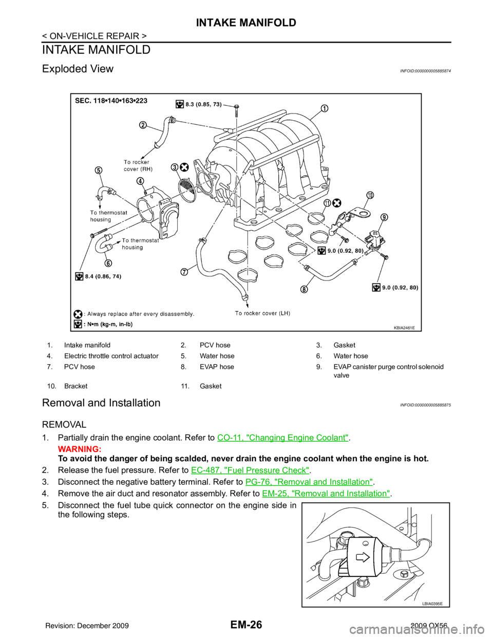
Exploded ViewINFOID:0000000005885874
Removal and InstallationINFOID:0000000005885875
REMOVAL
1. Partially drain the engine coolant. Refer to CO-11, "Changing Engine Coolant".
WARNING:
To avoid the danger of being scal ded, never drain the engine coolant when the engine is hot.
2. Release the fuel pressure. Refer to EC-487, "
Fuel Pressure Check".
3. Disconnect the negative battery terminal. Refer to PG-76, "
Removal and Installation".
4. Remove the air duct and resonator assembly. Refer to EM-25, "
Removal and Installation".
5. Disconnect the fuel tube quick connector on the engine side in the following steps.
1. Intake manifold 2. PCV hose 3. Gasket
4. Electric throttle control actuator 5. Water hose 6. Water hose
7. PCV hose 8. EVAP hose 9. EVAP canister purge control solenoid
valve
10. Bracket 11. Gasket
KBIA2461E
LBIA0395E
Revision: December 20092009 QX56
Page 1852 of 4171
INTAKE MANIFOLDEM-29
< ON-VEHICLE REPAIR >
C
DE
F
G H
I
J
K L
M A
EM
NP
O
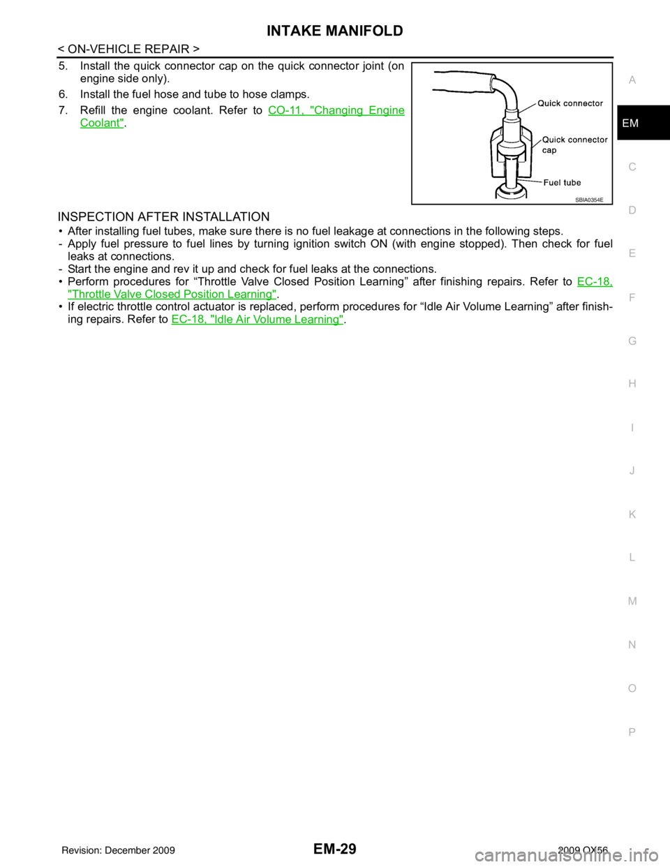
5. Install the quick connector cap on the quick connector joint (on
engine side only).
6. Install the fuel hose and tube to hose clamps.
7. Refill the engine coolant. Refer to CO-11, "
Changing Engine
Coolant".
INSPECTION AFTER INSTALLATION
• After installing fuel tubes, make sure there is no fuel leakage at connections in the following steps.
- Apply fuel pressure to fuel lines by turning ignition switch ON (with engine stopped). Then check for fuel leaks at connections.
- Start the engine and rev it up and check for fuel leaks at the connections.
• Perform procedures for “Throttle Valve Closed Position Learning” after finishing repairs. Refer to EC-18,
"Throttle Valve Closed Position Learning".
• If electric throttle control actuator is replaced, per form procedures for “Idle Air Volume Learning” after finish-
ing repairs. Refer to EC-18, "
Idle Air Volume Learning".
SBIA0354E
Revision: December 20092009 QX56
Page 1875 of 4171
EM-52
< ON-VEHICLE REPAIR >
TIMING CHAIN
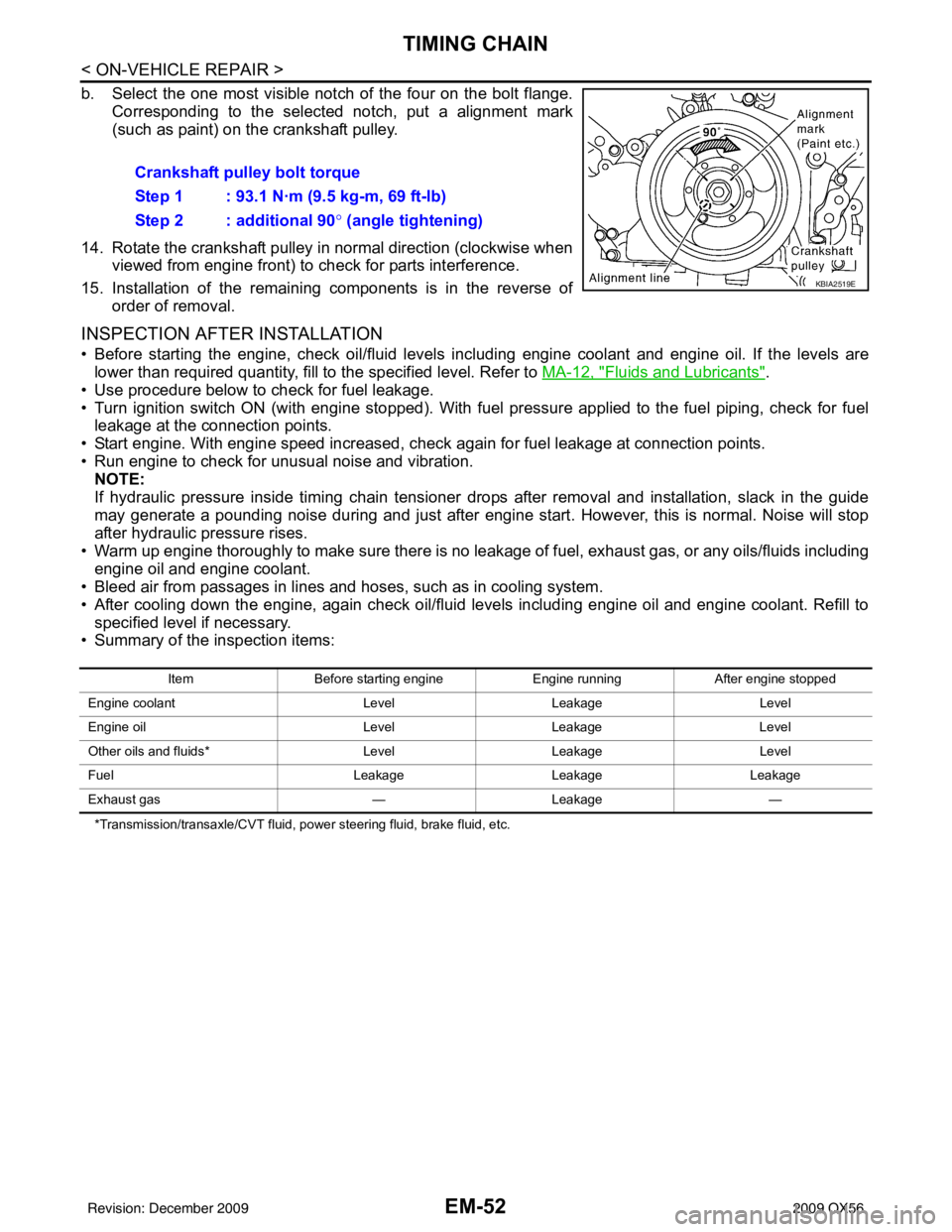
b. Select the one most visible notch of the four on the bolt flange.Corresponding to the selected notch, put a alignment mark
(such as paint) on the crankshaft pulley.
14. Rotate the crankshaft pulley in normal direction (clockwise when viewed from engine front) to check for parts interference.
15. Installation of the remaining components is in the reverse of order of removal.
INSPECTION AFTER INSTALLATION
• Before starting the engine, check oil/fluid levels in cluding engine coolant and engine oil. If the levels are
lower than required quantity, fill to the specified level. Refer to MA-12, "
Fluids and Lubricants".
• Use procedure below to check for fuel leakage.
• Turn ignition switch ON (with engine stopped). With fuel pressure applied to the fuel piping, check for fuel leakage at the connection points.
• Start engine. With engine speed increased, che ck again for fuel leakage at connection points.
• Run engine to check for unusual noise and vibration. NOTE:
If hydraulic pressure inside timing chain tensioner drops after removal and installation, slack in the guide
may generate a pounding noise during and just after engine start. However, this is normal. Noise will stop
after hydraulic pressure rises.
• Warm up engine thoroughly to make sure there is no leakage of fuel, exhaust gas, or any oils/fluids including engine oil and engine coolant.
• Bleed air from passages in lines and hoses, such as in cooling system.
• After cooling down the engine, again check oil/fluid levels including engine oil and engine coolant. Refill to
specified level if necessary.
• Summary of the inspection items:
*Transmission/transaxle/CVT fluid, power steering fluid, brake fluid, etc.
Crankshaft pulley bolt torque
Step 1 : 93.1 N·m (9.5 kg-m, 69 ft-lb)
Step 2 : additional 90 ° (angle tightening)
KBIA2519E
Item Before starting engine Engine runningAfter engine stopped
Engine coolant LevelLeakage Level
Engine oil LevelLeakage Level
Other oils and fluids* LevelLeakage Level
Fuel LeakageLeakageLeakage
Exhaust gas —Leakage —
Revision: December 20092009 QX56
Page 1891 of 4171
EM-68
< ON-VEHICLE REPAIR >
CYLINDER HEAD
CYLINDER HEAD
Exploded ViewINFOID:0000000005885894
Removal and InstallationINFOID:0000000005885895
REMOVAL
1. Remove the engine assembly from the vehicle. Refer to EM-78, "Removal and Installation".
2. Remove the following components and related parts: • Drive belt auto tensioner and idler pulley. Refer to EM-14, "
Drive Belt Auto Tensioner and Idler Pulley".
• Generator assembly and bracket. Refer to CHG-20, "
Removal and Installation".
• Thermostat housing and hose. Refer to CO-22, "
Removal and Installation".
• Oil pan and oil strainer. Refer to EM-33, "
Removal and Installation".
• Fuel tube and fuel injector assembly. Refer to EM-40, "
Removal and Installation".
• Intake manifold. Refer to EM-26, "
Removal and Installation".
• Rocker cover. Refer to EM-38, "
Removal and Installation".
3. Remove the crankshaft pulley, front cover, oil pump, and timing chain. Refer to EM-45, "
Removal and
Installation".
4. Remove the camshaft sprockets and camshafts. Refer to EM-53, "
Removal and Installation".
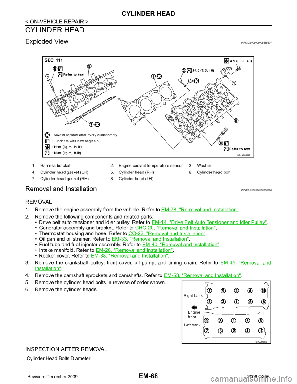
5. Remove the cylinder head bolts in reverse of order shown.
6. Remove the cylinder heads.
INSPECTION AFTER REMOVAL
Cylinder Head Bolts Diameter
1. Harness bracket 2. Engine coolant temperature sensor 3. Washer
4. Cylinder head gasket (LH) 5. Cylinder head (RH) 6. Cylinder head bolt
7. Cylinder head gasket (RH) 8. Cylinder head (LH)
KBIA2528E
PBIC0068E
Revision: December 20092009 QX56
Page 1892 of 4171
CYLINDER HEADEM-69
< ON-VEHICLE REPAIR >
C
DE
F
G H
I
J
K L
M A
EM
NP
O
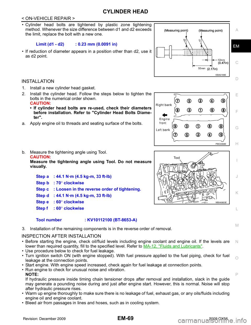
• Cylinder head bolts are tightened by plastic zone tightening
method. Whenever the size difference between d1 and d2 exceeds
the limit, replace the bolt with a new one.
• If reduction of diameter appears in a position other than d2, use it as d2 point.
INSTALLATION
1. Install a new cylinder head gasket.
2. Install the cylinder head. Follow the steps below to tighten the bolts in the numerical order shown.
CAUTION:
• If cylinder head bolts are re-used, check their diameters
before installation. Refer to "Cylinder Head Bolts Diame-
ter".
a. Apply engine oil to threads and seating surface of the bolts.
b. Measure the tightening angle using Tool. CAUTION:
Measure the tightening angl e using Tool. Do not measure
visually.
3. Installation of the remaining components is in the reverse order of removal.
INSPECTION AFTER INSTALLATION
• Before starting the engine, check oil/fluid levels including engine coolant and engine oil. If the levels are lower than required quantity, fill to the specified level. Refer to MA-12, "
Fluids and Lubricants".
• Use procedure below to check for fuel leakage.
• Turn ignition switch ON (with engine stopped). With fuel pressure applied to the fuel piping, check for fuel
leakage at the connection points.
• Start engine. With engine speed increased, check again for fuel leakage at connection points.
• Run engine to check for unusual noise and vibration.
NOTE:
If hydraulic pressure inside timing chain tensioner drops after removal and installation, slack in the guide
may generate a pounding noise during and just after engine start. However, this is normal. Noise will stop
after hydraulic pressure rises.
• Warm up engine thoroughly to make sure there is no leakage of fuel, exhaust gas, or any oils/fluids including
engine oil and engine coolant.
• Bleed air from passages in lines and hoses, such as in cooling system. Limit (d1 - d2) : 0.23 mm (0.0091 in)
KBIA0189E
PBIC0068E
Step a : 44.1 N·m (4.5 kg-m, 33 ft-lb)
Step b : 70°
clockwise
Step c : Loosen in the reverse order of tightening.
Step d : 44.1 N·m (4.5 kg-m, 33 ft-lb)
Step e : 60 ° clockwise
Step f : 60° clockwise
Tool number : KV10112100 (BT-8653-A)
WBIA0603E
Revision: December 20092009 QX56
Page 1893 of 4171
EM-70
< ON-VEHICLE REPAIR >
CYLINDER HEAD
• After cooling down the engine, again check oil/fluid levels including engine oil and engine coolant. Refill tospecified level if necessary.
• Summary of the inspection items:
*Transmission/transaxle/CVT fluid, power steering fluid, brake fluid, etc.
Exploded ViewINFOID:0000000005885896
Disassembly and AssemblyINFOID:0000000005885897
DISASSEMBLY
1. Remove the spark plug. Refer to EM-16, "Removal and Installation".
2. Remove the valve lifter. • Identify the installation positions, and store them without mixing them up.
Item Before starting engine Engine runningAfter engine stopped
Engine coolant LevelLeakage Level
Engine oil LevelLeakage Level
Other oils and fluids* LevelLeakage Level
Fuel LeakageLeakageLeakage
Exhaust gas —Leakage —
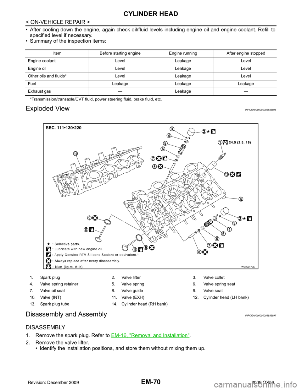
1. Spark plug 2. Valve lifter3. Valve collet
4. Valve spring retainer 5. Valve spring6. Valve spring seat
7. Valve oil seal 8. Valve guide9. Valve seat
10. Valve (INT) 11. Valve (EXH)12. Cylinder head (LH bank)
13. Spark plug tube 14. Cylinder head (RH bank)
WBIA0470E
Revision: December 20092009 QX56
Page 1895 of 4171
EM-72
< ON-VEHICLE REPAIR >
CYLINDER HEAD
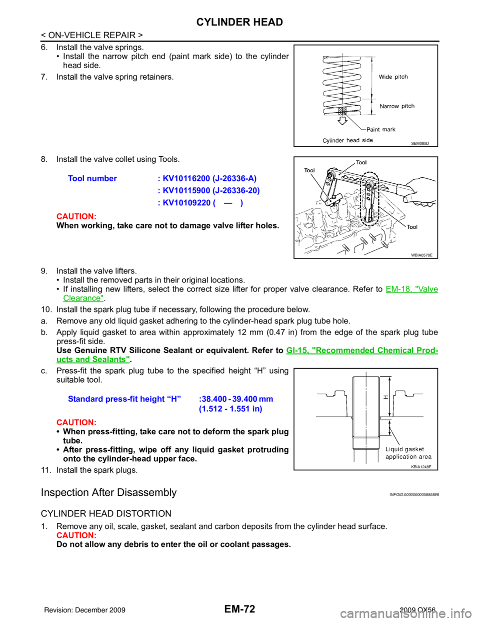
6. Install the valve springs.• Install the narrow pitch end (paint mark side) to the cylinderhead side.
7. Install the valve spring retainers.
8. Install the valve collet using Tools.
CAUTION:
When working, take care not to damage valve lifter holes.
9. Install the valve lifters. • Install the removed parts in their original locations.
• If installing new lifters, select the correct size lifter for proper valve clearance. Refer to EM-18, "
Va l v e
Clearance".
10. Install the spark plug tube if necessary, following the procedure below.
a. Remove any old liquid gasket adhering to the cylinder-head spark plug tube hole.
b. Apply liquid gasket to area within approximately 12 mm (0.47 in) from the edge of the spark plug tube
press-fit side.
Use Genuine RTV Silicone Seal ant or equivalent. Refer to GI-15, "
Recommended Chemical Prod-
ucts and Sealants".
c. Press-fit the spark plug tube to the specified height “H” using suitable tool.
CAUTION:
• When press-fitting, take care not to deform the spark plugtube.
• After press-fitting, wipe off any liquid gasket protruding
onto the cylinder-head upper face.
11. Install the spark plugs.
Inspection After DisassemblyINFOID:0000000005885898
CYLINDER HEAD DISTORTION
1. Remove any oil, scale, gasket, sealant and carbon deposits from the cylinder head surface. CAUTION:
Do not allow any debris to en ter the oil or coolant passages.
SEM085D
Tool number : KV10116200 (J-26336-A)
: KV10115900 (J-26336-20)
: KV10109220 ( — )
WBIA0578E
Standard press-fit height “H” :38.400 - 39.400 mm (1.512 - 1.551 in)
KBIA1248E
Revision: December 20092009 QX56