2009 INFINITI QX56 check engine light
[x] Cancel search: check engine lightPage 3679 of 4171
ON BOARD DIAGNOSTIC (OBD) SYSTEMTM-31
< FUNCTION DIAGNOSIS >
CEF
G H
I
J
K L
M A
B
TM
N
O P
longer stored. Remember, only one set of freeze frame data can be stored in the ECM. The ECM has the fol-
lowing priorities to update the data.
Both 1st trip freeze frame data and freeze frame data (along with the DTC) are cleared when the ECM mem-
ory is erased.
HOW TO ERASE DTC
The diagnostic trouble code can be erased by CONSULT- III, GST or ECM DIAGNOSTIC TEST MODE as
described following.
If the battery cable is disconnected, the diagnostic trouble code will be lost within 24 hours.
When you erase the DTC, using CONSULT-III or GS T is easier and quicker than switching the mode
selector on the ECM.
The following emission-related diagnostic information is cleared from the ECM memory when erasing DTC
related to OBD-II. For details, refer to EC-42, "Emission-related Diagnostic Information"
.
Diagnostic trouble codes (DTC)
1st trip diagnostic trouble codes (1st trip DTC)
Freeze frame data
1st trip freeze frame data
System readiness test (SRT) codes
Test values
HOW TO ERASE DTC (WITH CONSULT-III)
1. The emission related diagnostic information in the TCM and ECM can be er\
ased by selectioning "ALL
ERASE" in the "Description" of "F INAL CHECK" mode with CONSULT-III.
HOW TO ERASE DTC (WITH GST)
1. If the ignition switch stays “ON” after repair work, be sure to turn ignition switch “OFF” once. Wait at least
10 seconds and then turn it “ON” (engine stopped) again.
2. Select Mode 4 with the Generic Scan Tool (GST). For details refer to EC-72, "Generic Scan Tool (GST)
Function".
HOW TO ERASE DTC (NO TOOLS)
1. Disconnect battery for 24 hours.
2. Reconnect battery.
Malfunction Indicator Lamp (MIL)INFOID:0000000003771823
DESCRIPTION
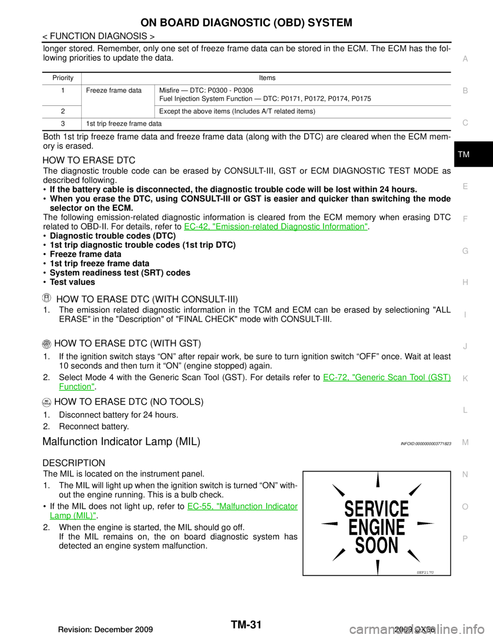
The MIL is located on the instrument panel.
1. The MIL will light up when the ignition switch is turned “ON” with-
out the engine running. This is a bulb check.
If the MIL does not light up, refer to EC-55, "Malfunction Indicator
Lamp (MIL)".
2. When the engine is start ed, the MIL should go off.
If the MIL remains on, the on board diagnostic system has
detected an engine system malfunction.
Priority Items
1 Freeze frame data Misfire — DTC: P0300 - P0306 Fuel Injection System Function — DTC: P0171, P0172, P0174, P0175
2 Except the above items (Includes A/T related items)
3 1st trip freeze frame data
SEF217U
Revision: December 20092009 QX56
Page 3685 of 4171
DIAGNOSIS SYSTEM (TCM)TM-37
< FUNCTION DIAGNOSIS >
CEF
G H
I
J
K L
M A
B
TM
N
O P
Diagnosis Procedure without CONSULT-IIIINFOID:0000000004024115
OBD-II SELF-DIAGNOSTIC PROCEDURE (WITH GST)
Refer to EC-72, "Generic Scan Tool (GST) Function".
OBD-II SELF-DIAGNOSTIC PROCEDURE (NO TOOLS)
Refer to EC-55, "Malfunction Indicator Lamp (MIL)".
TCM SELF-DIAGNOSTIC PROCEDURE (NO TOOLS)
Description
When the ignition switch is switched “ON”, the A/T CHECK indicator lamp lights up for 2 seconds. As a method
for locating the suspect circuit, w hen the self-diagnostics start signal is input, the memory for the malfunction
location is output and the A/T CHECK indicator lamp flashes to display the corresponding DTC.
Diagnostic Procedure
1.CHECK A/T CHECK INDICATOR LAMP
1. Start the engine with selector lever in “P” pos ition. Warm engine to normal operating temperature.
2. Turn ignition switch ON and OFF at least twice, then leave it in the OFF position.
3. Wait 10 seconds.
4. Turn ignition switch ON. (Do not start engine.)
Does A/T CHECK indicator lamp come on for about 2 seconds?
YES >> GO TO 2.
NO >> GO TO TM-119, "A/T Check Indicator Lamp Does Not Come On"
.
2.JUDGEMENT PROCEDURE STEP 1
1. Turn ignition switch OFF.
2. Keep pressing shift lock release button.
3. Move selector lever from “P” to “D” position.
4. Release accelerator pedal. (Set the closed throttle position signal “ON”.)
5. Depress brake pedal. (Stop lamp switch signal “ON”.)
6. Turn ignition switch ON. (Do not start engine.)
7. Wait 3 seconds.
8. Move the selector lever from “D” to “3” position.
9. Release brake pedal. (Stop lamp switch signal “OFF”.)
10. Move the selector lever from “3” to “2” position.
11. Depress brake pedal. (Stop lamp switch signal “ON”.)
DTC work support item Description Check item
1ST GR FUNCTN P0731 Following items for “” be confirmed.
Self-diagnosis status (whether the diagnosis is being performed
or not)
Self-diagnosis result (OK or NG)
Input clutch solenoid valve
Front brake solenoid valve
Direct clutch solenoid valve
High and low reverse clutch solenoid valve
Each clutch
Hydraulic co ntrol circuit
valve
2ND GR FUNCTN P0732
Following items for “” be confirmed.
Self-diagnosis status (whether the diagnosis is being performed
or not)
Self-diagnosis result (OK or NG)
3RD GR FUNCTN P0733 Following items for “” be confirmed.
Self-diagnosis status (whether the diagnosis is being performed
or not)
Self-diagnosis result (OK or NG)
4TH GR FUNCTN P0734 Following items for “” be confirmed.
Self-diagnosis status (whether the diagnosis is being performed
or not)
Self-diagnosis result (OK or NG)
5TH GR FUNCTN P0735 Following items for “” be confirmed.
Self-diagnosis status (whether the diagnosis is being performed
or not)
Self-diagnosis result (OK or NG)
Revision: December 20092009 QX56
Page 3752 of 4171
TM-104
< ECU DIAGNOSIS >
TCM
ECU DIAGNOSIS
TCM
Reference ValueINFOID:0000000003771985
REFERENCE VALUES
NOTICE:
1. The CONSULT-III electrically displays shift timing and lock-up timing (that is, operation timing of each
solenoid).
Check for time difference between actual shift timi ng and the CONSULT-III display. If the difference is
noticeable, mechanical parts (except solenoids, sens ors, etc.) may be malfunctioning. Check mechanical
parts using applicable diagnostic procedures.
2. Shift schedule (which implies gear position) display ed on CONSULT-III and that indicated in Service Man-
ual may differ slightly. This occurs because of the following reasons:
- Actual shift schedule has more or less tolerance or allowance,
- Shift schedule indicated in Service Manual refers to the point where shifts start, and
- Gear position displayed on CONSULT-III indicates the point where shifts are completed.
3. Display of solenoid valves on CONSULT-III changes at t he start of shifting, while gear position is displayed
upon completion of shifting (which is computed by TCM).
Item name Condition Display value (Approx.)
AT F T E M P S E 1 0 °C (32 ° F) - 20 °C (68 °F) - 80 °C (176 °F) 3.3 - 2.7 - 0.9 V
TCC SOLENOID When perform slip lock-up 0.2 - 0.4 A
When perform lock-up 0.4 - 0.6 A
SLCT LVR POSI Selector lever in “N”,“P” position. N/P
Selector lever in “R” position. R
Selector lever in “D” position. D
Selector lever in “4” position. 4
Selector lever in “3” position. 3
Selector lever in “2” position. 2
Selector lever in “1” position. 1
VHCL/S SE·A/T During driving Approximately matches the
speedometer reading.
ENGINE SPEED Engine running Closely matches the tachometer
reading.
LINE PRES SOL During driving 0.2 - 0.6 A
INPUT SPEED During driving (lock-up ON) Approximately matches the en-
gine speed.
VHCL/S SE·MTR During driving Approximately matches the
speedometer reading.
ATF PRES SW 2 Low coast brake engaged. Refer to
TM-9
ON
Low coast brake disengaged. Refer to TM-9
OFF
I/C SOLENOID Input clutch disengaged. Refer to
TM-9
0.6 - 0.8 A
Input clutch engaged. Refer to TM-9
0 - 0.05 A
FR/B SOLENOID Front brake engaged. Refer to
TM-9
0.6 - 0.8 A
Front brake disengaged. Refer to TM-9
0 - 0.05 A
D/C SOLENOID Direct clutch disengaged. Refer to
TM-9
0.6 - 0.8 A
Direct clutch engaged. Refer to TM-9
0 - 0.05 A
HLR/C SOL High and low reverse clutch disengaged. Refer to
TM-9
0.6 - 0.8 A
High and low reverse clutch engaged. Refer to TM-9
0 - 0.05 A
Revision: December 20092009 QX56
Page 3823 of 4171
PRECAUTIONSTM-175
< PRECAUTION >
CEF
G H
I
J
K L
M A
B
TM
N
O P
5. When the repair work is completed, return the ignition switch to the ″LOCK ″ position before connecting
the battery cables. (At this time, the steering lock mechanism will engage.)
6. Perform a self-diagnosis check of al l control units using CONSULT-III.
Precaution for On Board Diagnosis (OBD) System of A/T and EngineINFOID:0000000003772014
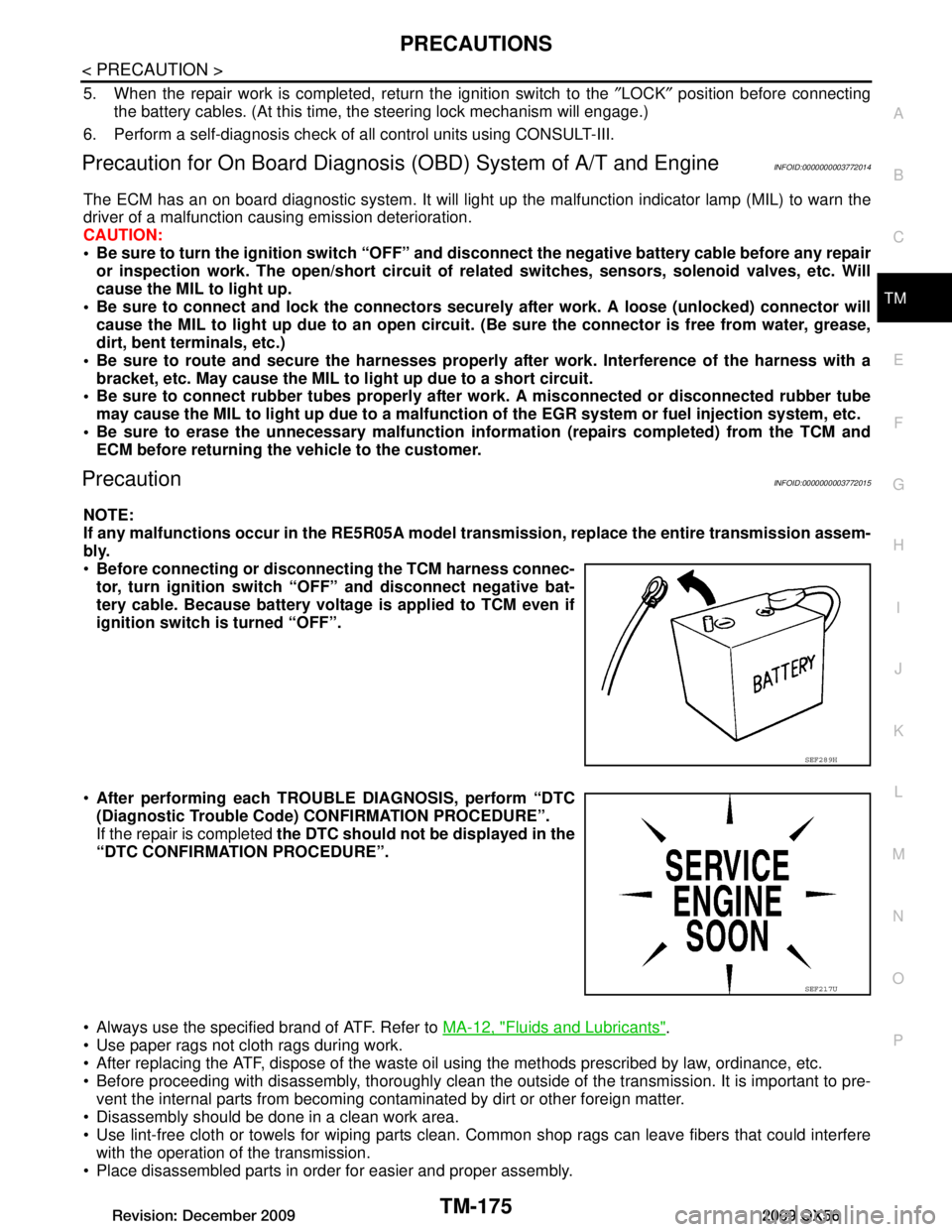
The ECM has an on board diagnostic system. It will light up the malfunction indicator lamp (MIL) to warn the
driver of a malfunction causing emission deterioration.
CAUTION:
Be sure to turn the ignition sw itch “OFF” and disconnect the negati ve battery cable before any repair
or inspection work. The open/short circuit of related switches, sensors, solenoid valves, etc. Will
cause the MIL to light up.
Be sure to connect and lock the connectors secure ly after work. A loose (unlocked) connector will
cause the MIL to light up due to an open circuit. (Be sure the connector is free from water, grease,
dirt, bent terminals, etc.)
Be sure to route and secure the harnesses properly after work. Interference of the harness with a
bracket, etc. May cause the MIL to li ght up due to a short circuit.
Be sure to connect rubber tubes properly afte r work. A misconnected or disconnected rubber tube
may cause the MIL to light up due to a malfunction of the EGR system or fuel injection system, etc.
Be sure to erase the unnecessary malfunction informa tion (repairs completed) from the TCM and
ECM before returning the vehicle to the customer.
PrecautionINFOID:0000000003772015
NOTE:
If any malfunctions occur in th e RE5R05A model transmission, repl ace the entire transmission assem-
bly.
Before connecting or disconn ecting the TCM harness connec-
tor, turn ignition switch “O FF” and disconnect negative bat-
tery cable. Because battery voltage is applied to TCM even if
ignition switch is turned “OFF”.
After performing each TROUBL E DIAGNOSIS, perform “DTC
(Diagnostic Trouble Code) CONFIRMATION PROCEDURE”.
If the repair is completed the DTC should not be displayed in the
“DTC CONFIRMATION PROCEDURE”.
Always use the specified brand of ATF. Refer to MA-12, "Fluids and Lubricants"
.
Use paper rags not cloth rags during work.
After replacing the ATF, dispose of the waste oil using the methods prescribed by law, ordinance, etc.
Before proceeding with disassembly, thoroughly clean the outsi de of the transmission. It is important to pre-
vent the internal parts from becoming contaminated by dirt or other foreign matter.
Disassembly should be done in a clean work area.
Use lint-free cloth or towels for wiping parts clean. Common shop rags can leave fibers that could interfere
with the operation of the transmission.
Place disassembled parts in order for easier and proper assembly.
SEF289H
SEF217U
Revision: December 20092009 QX56
Page 3838 of 4171
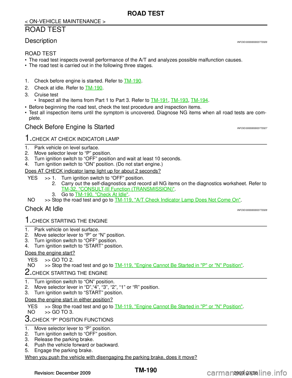
TM-190
< ON-VEHICLE MAINTENANCE >
ROAD TEST
ROAD TEST
DescriptionINFOID:0000000003772026
ROAD TEST
The road test inspects overall performance of the A/T and analyzes possible malfunction causes.
The road test is carried out in the following three stages.
1. Check before engine is started. Refer to TM-190
.
2. Check at idle. Refer to TM-190
.
3. Cruise test Inspect all the items from Part 1 to Part 3. Refer to TM-191
, TM-193, TM-194.
Before beginning the road test, check t he test procedure and inspection items.
Test all inspection items until the symptom is unc overed. Diagnose NG items when all road tests are com-
plete.
Check Before Engine Is StartedINFOID:0000000003772027
1.CHECK AT CHECK INDICATOR LAMP
1. Park vehicle on level surface.
2. Move selector lever to “P” position.
3. Turn ignition switch to “OFF” position and wait at least 10 seconds.
4. Turn ignition switch to “ON” position. (Do not start engine.)
Does AT CHECK indicator lamp light up for about 2 seconds?
YES >> 1. Turn ignition switch to “OFF” position. 2. Carry out the self-diagnostics and record al l NG items on the diagnostics worksheet. Refer to
TM-32, "CONSULT-III Function (TRANSMISSION)"
.
3. Go to TM-190, "Check At Idle"
.
NO >> Stop the road test and go to TM-119, "A/T Check Indicator Lamp Does Not Come On"
.
Check At IdleINFOID:0000000003772028
1.CHECK STARTING THE ENGINE
1. Park vehicle on level surface.
2. Move selector lever to “P” or “N” position.
3. Turn ignition switch to “OFF” position.
4. Turn ignition switch to “START” position.
Does the engine start?
YES >> GO TO 2.
NO >> Stop the road test and go to TM-119, "Engine Cannot Be Started in "P" or "N" Position"
.
2.CHECK STARTING THE ENGINE
1. Turn ignition switch to “ON” position.
2. Move selector lever in “D”,“4”, “3”, “2”, “1” or “R” position.
3. Turn ignition switch to “START” position.
Does the engine start in either position?
YES >> Stop the road test and go to TM-119, "Engine Cannot Be Started in "P" or "N" Position".
NO >> GO TO 3.
3.CHECK “P” POSITION FUNCTIONS
1. Move selector lever to “P” position.
2. Turn ignition switch to “OFF” position.
3. Release the parking brake.
4. Push the vehicle forward or backward.
5. Engage the parking brake.
When you push the vehicle with disengaging the parking brake, does it move?
Revision: December 20092009 QX56
Page 3841 of 4171
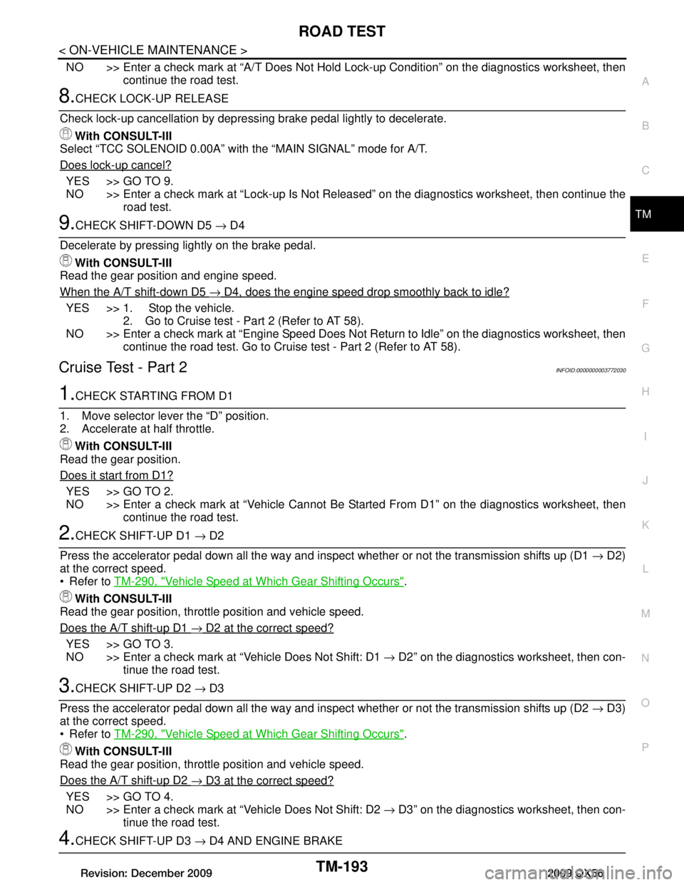
ROAD TESTTM-193
< ON-VEHICLE MAINTENANCE >
CEF
G H
I
J
K L
M A
B
TM
N
O P
NO >> Enter a check mark at “A/T Does Not Hold Lock-up Condition” on the diagnostics worksheet, then
continue the road test.
8.CHECK LOCK-UP RELEASE
Check lock-up cancellation by depressi ng brake pedal lightly to decelerate.
With CONSULT-III
Select “TCC SOLENOID 0.00A” with the “MAIN SIGNAL” mode for A/T.
Does lock-up cancel?
YES >> GO TO 9.
NO >> Enter a check mark at “Lock-up Is Not Rel eased” on the diagnostics worksheet, then continue the
road test.
9.CHECK SHIFT-DOWN D5 → D4
Decelerate by pressing lightly on the brake pedal. With CONSULT-III
Read the gear position and engine speed.
When the A/T shift-down D5
→ D4, does the engine speed drop smoothly back to idle?
YES >> 1. Stop the vehicle. 2. Go to Cruise test - Part 2 (Refer to AT 58).
NO >> Enter a check mark at “Engine Speed Does Not Return to Idle” on the diagnostics worksheet, then continue the road test. Go to Cruise test - Part 2 (Refer to AT 58).
Cruise Test - Part 2INFOID:0000000003772030
1.CHECK STARTING FROM D1
1. Move selector lever the “D” position.
2. Accelerate at half throttle. With CONSULT-III
Read the gear position.
Does it start from D1?
YES >> GO TO 2.
NO >> Enter a check mark at “Vehicle Cannot Be St arted From D1” on the diagnostics worksheet, then
continue the road test.
2.CHECK SHIFT-UP D1 → D2
Press the accelerator pedal down all the way and inspect whether or not the transmission shifts up (D1 → D2)
at the correct speed.
Refer to TM-290, "Vehicle Speed at Which Gear Shifting Occurs"
.
With CONSULT-III
Read the gear position, thrott le position and vehicle speed.
Does the A/T shift-up D1
→ D2 at the correct speed?
YES >> GO TO 3.
NO >> Enter a check mark at “Vehicle Does Not Shift: D1 → D2” on the diagnostics worksheet, then con-
tinue the road test.
3.CHECK SHIFT-UP D2 → D3
Press the accelerator pedal down all the way and inspect whether or not the transmission shifts up (D2 → D3)
at the correct speed.
Refer to TM-290, "Vehicle Speed at Which Gear Shifting Occurs"
.
With CONSULT-III
Read the gear position, thrott le position and vehicle speed.
Does the A/T shift-up D2
→ D3 at the correct speed?
YES >> GO TO 4.
NO >> Enter a check mark at “Vehicle Does Not Shift: D2 → D3” on the diagnostics worksheet, then con-
tinue the road test.
4.CHECK SHIFT-UP D3 → D4 AND ENGINE BRAKE
Revision: December 20092009 QX56
Page 4024 of 4171
WCS
COMBINATION METERWCS-47
< ECU DIAGNOSIS >
C
DE
F
G H
I
J
K L
M B A
O P
DTC IndexINFOID:0000000004115463
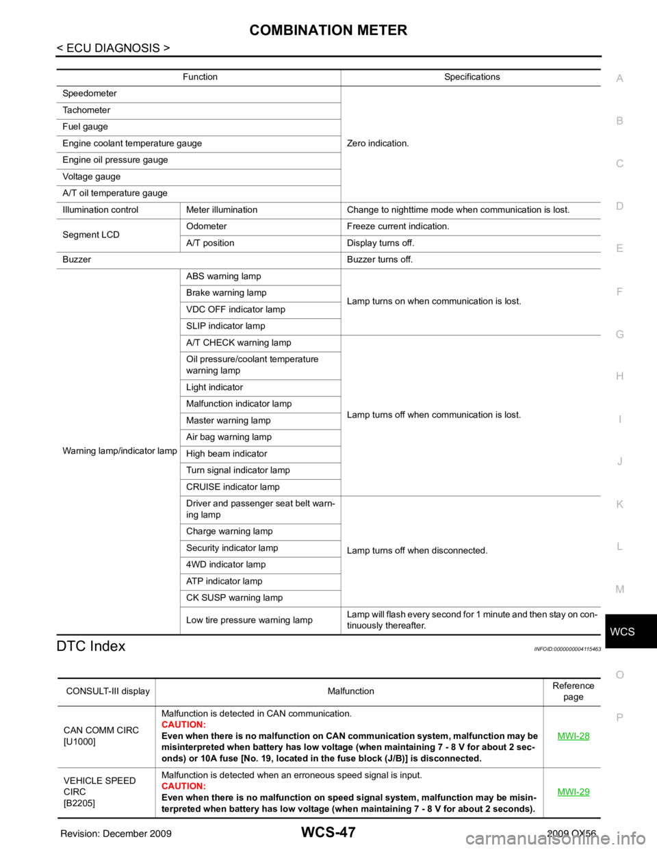
Function Specifications
Speedometer
Zero indication.
Tachometer
Fuel gauge
Engine coolant temperature gauge
Engine oil pressure gauge
Voltage gauge
A/T oil temperature gauge
Illumination control
Meter illumination Change to nighttime mode when communication is lost.
Segment LCD Odometer
Freeze current indication.
A/T position Display turns off.
Buzzer Buzzer turns off.
Warning lamp/indicator lamp ABS warning lamp
Lamp turns on when communication is lost.
Brake warning lamp
VDC OFF indicator lamp
SLIP indicator lamp
A/T CHECK warning lamp
Lamp turns off when communication is lost.
Oil pressure/coolant temperature
warning lamp
Light indicator
Malfunction indicator lamp
Master warning lamp
Air bag warning lamp
High beam indicator
Turn signal indicator lamp
CRUISE indicator lamp
Driver and passenger seat belt warn-
ing lamp
Lamp turns off when disconnected.
Charge warning lamp
Security indicator lamp
4WD indicator lamp
ATP indicator lamp
CK SUSP warning lamp
Low tire pressu
re warning lamp Lamp will flash every second for 1 minute and then stay on con-
tinuously thereafter.
CONSULT-III display
MalfunctionReference
page
CAN COMM CIRC
[U1000] Malfunction is detected in CAN communication.
CAUTION:
Even when there is no ma
lfunction on CAN communication system, malfunction may be
misinterpreted when battery has low voltag e (when maintaining 7 - 8 V for about 2 sec-
onds) or 10A fuse [No. 19, located in the fuse block (J/B)] is disconnected. MWI-28
VEHICLE SPEED
CIRC
[B2205]Malfunction is detected when an erroneous speed signal is input.
CAUTION:
Even when there is no malfunction on speed signal system, malfunction may be misin-
terpreted when battery has low voltage (whe
n maintaining 7 - 8 V for about 2 seconds). MWI-29
Revision: December 20092009 QX56