Page 50 of 273
1
FEATURES OF YOUR HYUNDAI
39
!
WARNING:
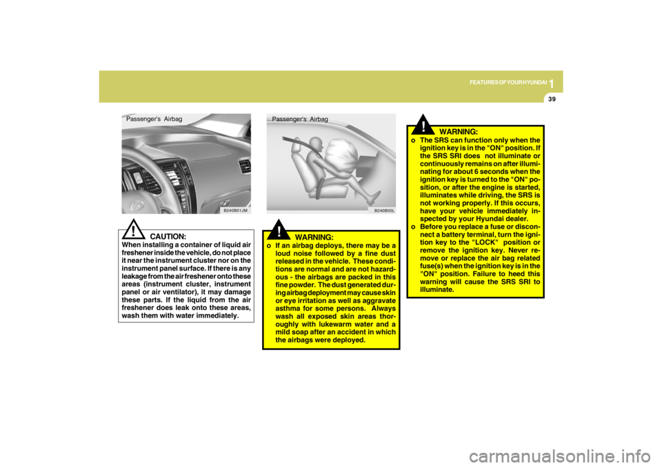
o If an airbag deploys, there may be a
loud noise followed by a fine dust
released in the vehicle. These condi-
tions are normal and are not hazard-
ous - the airbags are packed in this
fine powder. The dust generated dur-
ing airbag deployment may cause skin
or eye irritation as well as aggravate
asthma for some persons. Always
wash all exposed skin areas thor-
oughly with lukewarm water and a
mild soap after an accident in which
the airbags were deployed.Passenger's Airbag
B240B05L
!
o The SRS can function only when the
ignition key is in the "ON" position. If
the SRS SRI does not illuminate or
continuously remains on after illumi-
nating for about 6 seconds when the
ignition key is turned to the "ON" po-
sition, or after the engine is started,
illuminates while driving, the SRS is
not working properly. If this occurs,
have your vehicle immediately in-
spected by your Hyundai dealer.
o Before you replace a fuse or discon-
nect a battery terminal, turn the igni-
tion key to the "LOCK" position or
remove the ignition key. Never re-
move or replace the air bag related
fuse(s) when the ignition key is in the
"ON" position. Failure to heed this
warning will cause the SRS SRI to
illuminate.
WARNING:
CAUTION:
When installing a container of liquid air
freshener inside the vehicle, do not place
it near the instrument cluster nor on the
instrument panel surface. If there is any
leakage from the air freshener onto these
areas (instrument cluster, instrument
panel or air ventilator), it may damage
these parts. If the liquid from the air
freshener does leak onto these areas,
wash them with water immediately.
!Passenger's Airbag
B240B01JM
Page 70 of 273
1
FEATURES OF YOUR HYUNDAI
59
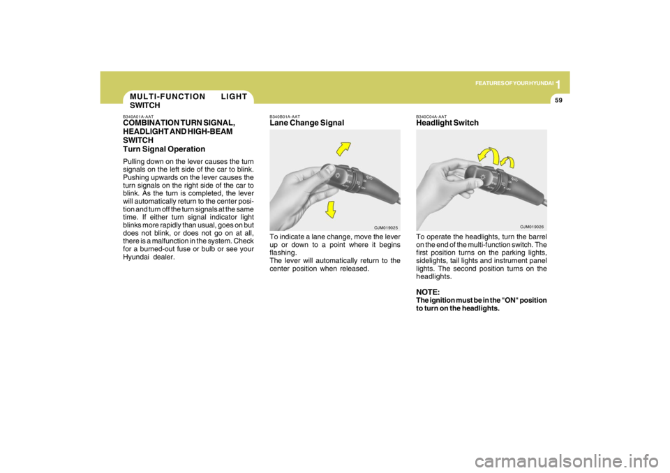
B340C04A-AATHeadlight SwitchTo operate the headlights, turn the barrel
on the end of the multi-function switch. The
first position turns on the parking lights,
sidelights, tail lights and instrument panel
lights. The second position turns on the
headlights.NOTE:The ignition must be in the "ON" position
to turn on the headlights.
OJM019026
MULTI-FUNCTION LIGHT
SWITCHB340A01A-AATCOMBINATION TURN SIGNAL,
HEADLIGHT AND HIGH-BEAM
SWITCH
Turn Signal OperationPulling down on the lever causes the turn
signals on the left side of the car to blink.
Pushing upwards on the lever causes the
turn signals on the right side of the car to
blink. As the turn is completed, the lever
will automatically return to the center posi-
tion and turn off the turn signals at the same
time. If either turn signal indicator light
blinks more rapidly than usual, goes on but
does not blink, or does not go on at all,
there is a malfunction in the system. Check
for a burned-out fuse or bulb or see your
Hyundai dealer.
B340B01A-AATLane Change SignalTo indicate a lane change, move the lever
up or down to a point where it begins
flashing.
The lever will automatically return to the
center position when released.
OJM019025
Page 205 of 273
6
Engine Compartment .................................................... 6-2
General Checks ............................................................ 6-4
Checking the Engine Oil ............................................... 6-5
Changing the Oil and Filter ............................................ 6-6
Checking and Changing the Engine Coolant ................ 6-8
Changing the Air Cleaner Filter ...................................6-10
Checking the Transaxle Oil (Manual) .........................6-11
Checking the Transaxle Fluid (Automatic)..................6-12
Checking the Brakes ..................................................6-14
Checking the Clutch Fluid...........................................6-15
Air Conditioning Care..................................................6-16
Changing the Climate Control Air Filter .......................6-17
Checking the Free-play...............................................6-19
Checking Drive Belts ..................................................6-20
Checking and Replacing Fuses..................................6-21
Checking the Battery..................................................6-23
Power Steering Fluid Level .........................................6-25
Replacement of Light Bulbs ........................................6-27
Bulb Wattage ...............................................................6-34
Fuse Panel Description...............................................6-35
6
DO-IT-YOURSELF MAINTENANCE
Page 206 of 273
6
DO-IT-YOURSELF MAINTENANCE
2
ENGINE COMPARTMENTG010A01JM-GAT(2.7 Gasoline)1. Power steering fluid reservoir
2. Brake & Clutch fluid reservoir
3. Air cleaner
4. Fuse and Relay box5. Windshield washer fluid reservoir
6. Engine oil level dipstick
7. Coolant reservoir cap
8. Engine oil filler cap9. Automatic transaxle fluid level dipstick
(Vehicle with Automatic Transaxle)
10. Radiator cap
11. Battery
G010A01JM
CAUTION:
When inspecting or servicing the
engine, you should handle tools
and other heavy objects care-
fully so that the plastic cover of
the engine is not damaged.
!
Page 207 of 273
6
DO-IT-YOURSELF MAINTENANCE
3
G010B01JM-AAT(2.0 Gasoline)
G010B01JM
1. Power steering fluid reservoir
2. Engine oil filler cap
3. Brake & Clutch fluid reservoir
4. Air cleaner5. Fuse and Relay box
6. Windshield washer fluid reservoir
7. Engine oil level dipstick
8. Coolant reservoir cap9. Automatic transaxle fluid level dipstick
(Vehicle with Automatic Transaxle)
10. Radiator cap
11. Battery
CAUTION:
When inspecting or servicing the
engine, you should handle tools
and other heavy objects care-
fully so that the plastic cover of
the engine is not damaged.
!
Page 225 of 273
6
DO-IT-YOURSELF MAINTENANCE
21
CHECKING AND REPLACING
FUSES
!
G200B02JM-AATReplacing Accessory Fuses
CAUTION:
When replacing a fusible link, never use
anything but a new fusible link with the
same or lower amperage rating. Never
use a piece of wire or a higher-rated
fusible link. This could result in serious
damage and create a fire hazard.
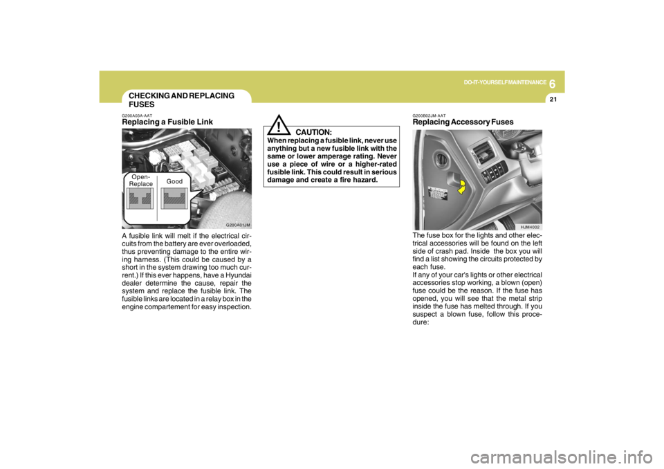
The fuse box for the lights and other elec-
trical accessories will be found on the left
side of crash pad. Inside the box you will
find a list showing the circuits protected by
each fuse.
If any of your car's lights or other electrical
accessories stop working, a blown (open)
fuse could be the reason. If the fuse has
opened, you will see that the metal strip
inside the fuse has melted through. If you
suspect a blown fuse, follow this proce-
dure:
G200A03A-AATReplacing a Fusible LinkA fusible link will melt if the electrical cir-
cuits from the battery are ever overloaded,
thus preventing damage to the entire wir-
ing harness. (This could be caused by a
short in the system drawing too much cur-
rent.) If this ever happens, have a Hyundai
dealer determine the cause, repair the
system and replace the fusible link. The
fusible links are located in a relay box in the
engine compartement for easy inspection.
HJM4002
G200A01JM
Open-
ReplaceGood
Page 226 of 273
6
DO-IT-YOURSELF MAINTENANCE
22
G200B02L
!
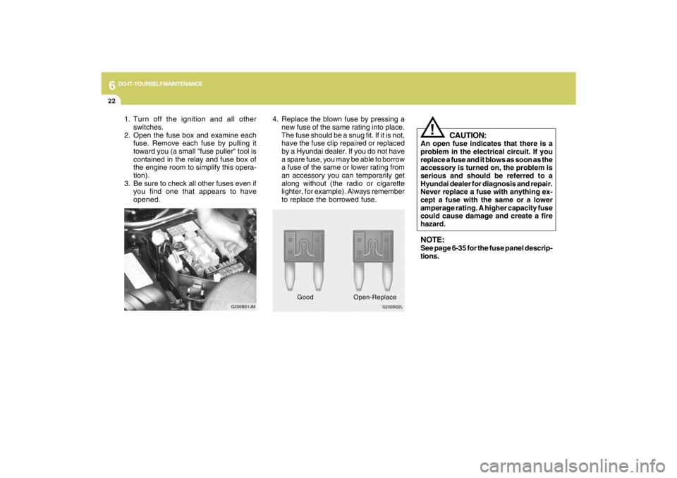
4. Replace the blown fuse by pressing a
new fuse of the same rating into place.
The fuse should be a snug fit. If it is not,
have the fuse clip repaired or replaced
by a Hyundai dealer. If you do not have
a spare fuse, you may be able to borrow
a fuse of the same or lower rating from
an accessory you can temporarily get
along without (the radio or cigarette
lighter, for example). Always remember
to replace the borrowed fuse.
CAUTION:
An open fuse indicates that there is a
problem in the electrical circuit. If you
replace a fuse and it blows as soon as the
accessory is turned on, the problem is
serious and should be referred to a
Hyundai dealer for diagnosis and repair.
Never replace a fuse with anything ex-
cept a fuse with the same or a lower
amperage rating. A higher capacity fuse
could cause damage and create a fire
hazard.NOTE:See page 6-35 for the fuse panel descrip-
tions.
GoodOpen-Replace
1. Turn off the ignition and all other
switches.
2. Open the fuse box and examine each
fuse. Remove each fuse by pulling it
toward you (a small "fuse puller" tool is
contained in the relay and fuse box of
the engine room to simplify this opera-
tion).
3. Be sure to check all other fuses even if
you find one that appears to have
opened.
G200B01JM
Page 239 of 273
6
DO-IT-YOURSELF MAINTENANCE
35
FUSE PANEL DESCRIPTIONG200C01JM-GATEngine Compartment
G200C01JM
NOTE:Not all fuse panel descriptions in this manual may be applicable to your vehicle. It is accurate at the time of printing. When you
inspect the fuse box on your vehicle, refer to the fuse box label.
FUSE
RATING
30A
30A
50A
50A
30A
40A
30A
30A
15A
10A
15A
15A
15A
15A
15A
15APROTECTED COMPONENTS
Start relay, Ignition switch
Engine control, Fuel pump , A/C, Generator, ATM
Ignition switch, Power connector
Cooling fan
ABS, ESC
ABS, ESC
Blower
Ignition switch, Power connector
Injector
Cooling fan, Stop lamp switch, Oxygen sensor, ECM/PCM
DRL
Front fog lamp
Horn, Siren
A/C
Head lamp (HIGH)
Head lamp (LOW)
IGN
ECU
BATT #1
C/FAN
ABS #1
ABS #2
BLOWER
BATT #2
INJ
SNSR
DRL
F/FOG
HORN
A/CON
H/LP (HI)
H/LP (LOW) FUSIBLE
LINK
FUSE
DESCRIPTION