2009 HYUNDAI TUCSON fuel filter
[x] Cancel search: fuel filterPage 198 of 273

5
VEHICLE MAINTENANCE REQUIREMENTS4
R: 100.000 miles / 120 months
SCHEDULED MAINTENANCEF030B03JM-AATR :Replace I : Inspect and, after Inspection, clean, adjust, repair or replace if necessary.
DESCRIPTION
EMISSION CONTROL ITEMS
ENGINE OIL AND FILTER
FUEL FILTER
FUEL LINES, FUEL HOSES AND CONNECTIONS
VACUUM HOSES
CRANKCASE VENTILATION HOSE
VAPOR HOSE AND FUEL FILLER CAP
AIR CLEANER FILTER
FUEL TANK AIR FILTER
SPARK PLUGS (PLATINUM COATED) - 2.0L
SPARK PLUGS (IRIDIUM COATED) - 2.7L
VALVE CLEARANCE (2.0L only) No.
1
2
3
4
5
6
7
8
9
10MILES X 1000
KILOMETERS X 1000
MONTHS7.5
12
6
R
I15
24
12
R
I
I22.5
36
18
R
I30
48
24
R
I
I
I
R
R37.5
60
30
R
I45
72
36
R
I
I52.5
84
42
R
R
I
I60
96
48
R
I
I
I
R
R
R
I67.5
108
54
R
I75
120
60
R
I
I82.5
132
66
R
I90
144
72
R
I
I
I
R
R97.5
156
78
R
I105
168
84
R
R
I
I
I112.5
180
90
R
I120
192
96
R
I
I
I
R
R
R
I127.5
204
102
R
I135
216
108
R
I
I142.5
228
114
R
I150
240
120
R
I
I
I
R
R
F030A01A-AATThe following maintenance services must be performed to ensure good emission control and performance. Keep receipts for all vehicle
emission services to protect your warranty. Where both mileage and time are shown, the frequency of service is determined by whichever
occurs first.
Page 201 of 273

5
VEHICLE MAINTENANCE REQUIREMENTS
7
F060D01A-AATo Fuel Lines, Fuel Hoses and Con-
nectionsCheck the fuel lines, fuel hoses and con-
nections for leakage and damage. Have a
trained technician replace any damaged
or leaking parts immediately.F060B01A-AATo Drive BeltsInspect all drive belts for evidence of cuts,
cracks, excessive wear or oil saturation
and replace if necessary. Drive belts should
be checked periodically for proper tension
and adjusted as necessary.
F060M01A-AATo Engine Oil and FilterThe engine oil and filter should be changed
at the intervals specified in the mainte-
nance schedule. If the car is being driven
in severe conditions, more frequent oil and
filter changes are required.F060C01A-AATo Fuel FilterA clogged filter can limit the speed at which
the vehicle may be driven, damage the
emission system and cause hard starting.
If an excessive amount of foreign matter
accumulates in the fuel tank, the filter may
require replacement more frequently.
After installing a new filter, run the engine
for several minutes, and check for leaks at
the connections. Fuel filters should be
installed by trained technicians.
F060F01O-AATo Vacuum HosesInspect the surface of hoses for evidence
of heat and/or mechanical damage. Hard
and brittle rubber, cracking, tears, cuts,
abrasions, and excessive swelling indi-
cate deterioration. Particular attention
should be paid to examine those hose
surfaces nearest to high heat sources,
such as the exhaust manifold.
Inspect the hose routing to assure that the
hoses do not come in contact with any heat
source, sharp edges or moving compo-
nent which might cause heat damage or
mechanical wear. Inspect all hose con-
nections, such as clamps and couplings,
to make sure they are secure, and that no
leaks are present. Hoses should be re-
placed immediately if there is any evi-
dence of deterioration or damage.
EXPLANATION OF SCHEDULED MAINTENANCE
ITEMS
Page 202 of 273

5
VEHICLE MAINTENANCE REQUIREMENTS8
F070D01A-AATo Manual Transaxle OilInspect the manual transaxle oil according
to the maintenance schedule.NOTE:If the oil level is low, check for possible
leaks before adding oil. Do not overfill.
F070C01A-AATo CoolantThe coolant should be changed at the
intervals specified in the maintenance
schedule.F060E01A-AATo Timing BeltInspect all parts related to the timing belt for
damage and deformation. Replace any
damaged parts immediately.F060J01A-AATo Spark PlugsMake sure to install new spark plugs of the
correct heat range.F060H01A-AATo Air Cleaner FilterA Genuine Hyundai air cleaner filter is
recommended when the filter is replaced.
F060G01A-AATo Vapor Hose and Fuel Filler CapThe vapor hose and fuel filler cap should
be inspected at those intervals specified in
the maintenance schedule. Make sure that
a new vapor hose or fuel filler cap is cor-
rectly replaced.F065F01O-AATo Crankcase Ventilation HoseInspect the surface of hose for evidence of
heat and/or mechanical damage. Hard
and brittle rubber, cracking, tears, cuts,
abrasions, and excessive swelling indi-
cate deterioration. Particular attention
should be paid to examine that hose sur-
face nearest to high heat sources, such as
the exhaust manifold.
Inspect the hose routing to assure that the
hose does not come in contact with any
heat source, sharp edges or moving com-
ponent which might cause heat damage or
mechanical wear. Inspect all hose con-
nections, such as clamps and couplings,
to make sure they are secure, and that no
leaks are present. Hose should be re-
placed immediately if there is any evi-
dence of deterioration or damage.
F070E06A-AATo Automatic Transaxle FluidThe fluid level should be in the “HOT”
range of the dipstick, after the engine and
transaxle are at normal operating tem-
perature. Check the automatic transaxle
fluid level with the engine running and the
transaxle in neutral, with the parking brake
properly applied. Use HYUNDAI GENU-
INE ATF SP III, DIAMOND ATF SP III, SK
ATF SP III or other brands meeting the SP
III specification approved by Hyundai Motor
Co. when adding or changing fluid. Using
the wrong ATF may result in damage to the
ATM.
Page 242 of 273

6
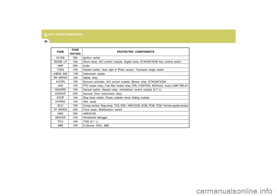
DO-IT-YOURSELF MAINTENANCE
38
FUSE
IG-SW
ROOM LP
AMP
T/SIG
A/BAG IND
RR WIPER
A/CON
IGN
HAZARD
S/ROOF
STOP
H/FREE
ECU
FF WIPER
4WD
DEICER
TCU
ABS
PROTECTED COMPONENTS
Ignition switch
Room lamp, A/C control module, Digital clock, ETACM/TACM Key remind switch
Audio
Hazard switch, Auto light & Photo sensor, Transaxle range switch
Instrument cluster
Safety relay
Sunroof controller, A/C control module, Blower relay, ETACM/TACM
PTC heater relay, Fuel filter heater relay, DRL CONTROL MODULE, head LAMP RELAY
Hazard switch, Hazard relay, Immobilizer control module (2.7 L)
Sunroof, Door lock/unlock relay
Stop lamp switch, Power outside mirror folding module
(Not used)
Cruise control, Stop lamp, TCS, ESC, 4WD ECM, ECM, PCM, TCM, Vehicle speed sensor
Front wiper, Multifunction switch
4WD/ECM
Windshield defogger
TCM (2.7 L)
G-Sensor, ESC, ABS FUSE
RATING
30A
10A
20A
10A
10A
15A
10A
10A
10A
20A
15A
10A
10A
20A
20A
15A
10A
10A
Page 244 of 273

7
EMISSION CONTROL SYSTEMS2
EMISSION CONTROL SYSTEM
H010D01A-AAT3. Exhaust Emission Control
SystemThe Exhaust Emission Control System is a
highly effective system which controls ex-
haust emissions while maintaining good
vehicle performace.
H010B01A-AAT1. Crankcase Emission Control
SystemThe positive crankcase ventilation system
is employed to prevent air pollution caused
by blow-by gases being emitted from the
crankcase. This system supplies filtered
air to the crankcase through the air intake
hose. Inside the crankcase, the fresh air
mixes with blow-by gases, which then pass
through the PCV valve and into the induc-
tion system.
H010A02O-AATYour Hyundai is equipped with an emis-
sion control system to meet all require-
ments of the U.S. Environmental Protec-
tion Agency or California Air Resources
Board.
There are three emission control systems
which are as follows.
(1) Crankcase emission control system
(2) Evaporative emission control system
(3) Exhaust emission control system
In order to assure the proper function of the
emission control systems, it is recom-
mended that you have your car inspected
and maintained by an authorized Hyundai
dealer in accordance with the maintenance
schedule in this manual.
Caution for the Inspection and Mainte-
nance Test (V6 Vehicle with Traction
Control System)
o To prevent the vehicle from misfiring
during dynamometer testing, discon-
nect the ABS connector in the engine
compartment. (2.7 V6 only)
o For more information, see shop manual
(Wheel Speed Sensor).
o After dynamometer testing is com-
pleted, erase the ABS/TCS DTC
(Diagnotic Trouble Code) with a GST
(Generic Scan Tool) or Hi-Scan Pro.
CanisterFuel vapors generated inside the fuel tank
are absorbed and stored in the canister.
When the engine is running, the fuel va-
pors absorbed in the canister are drawn
into the induction system through the purge
control solenoid valve.Purge Control Solenoid Valve (PCSV)The purge control solenoid valve is con-
trolled by the Engine Control Module
(ECM); when the engine coolant tempera-
ture is low during idling, the PCSV closes
so that evaporated fuel is not taken into the
engine. After the engine warms-up during
ordinary driving, the PCSV opens to intro-
duce evaporated fuel to the engine.
H010C01S-AAT2. Evaporative Emission Control (In-
cluding ORVR: Onboard Refuel-
ing Vapor Recovery) SystemThe Evaporative Emission Control Sys-
tem is designed to prevent fuel vapors from
escaping into the atmosphere.
(The ORVR system is designed to allow
the vapors from the fuel tank to be loaded
into a canister while refueling at the gas
station, preventing the escape of fuel va-
pors into the atmosphere.)