2009 Hyundai Sonata fuel
[x] Cancel search: fuelPage 257 of 286
7
EMISSION CONTROL SYSTEMS2
EMISSION CONTROL
SYSTEMS
H010B01A-AAT1. Crankcase Emission Control Sys-
temThe positive crankcase ventilation system
is employed to prevent air pollution caused
by blow-by gases being emitted from the
crankcase. This system supplies fresh
filtered air to the crankcase through the air
intake hose. Inside the crankcase, the fresh
air mixes with blow-by gases, which then
pass through the PCV valve into the
induction system.
CanisterFuel vapors generated inside the fuel tank
are absorbed and stored in the onboard
canister. When the engine is running, the
fuel vapors absorbed in the canister are
drawn into the surge tank through the
purge control solenoid valve.Purge Control Solenoid Valve (PCSV)The purge control solenoid valve is
controlled by the Engine Control Module
(ECM); when the engine coolant
temperature is low during idling, the PCSV
closes so that evaporated fuel is not taken
into the engine. After the engine warms-up
during ordinary driving, the PCSV opens
to introduce evaporated fuel to the engine.H010D01A-AAT3. Exhaust Emission Control
SystemThe Exhaust Emission Control System is a
highly effective system which controls
exhaust emissions while maintaining good
vehicle performance.
H010A01NF-AATYour Hyundai is equipped with an emission
control system to meet all emission
regulations.
There are three emission control systems
which are as follows.
(1) Crankcase emission control system
(2) Evaporative emission control system
(3) Exhaust emission control system
In order to assure the proper function of the
emission control systems, it is
recommended that you have your car
inspected and maintained by an authorized
Hyundai dealer in accordance with the
maintenance schedule in this manual.
Caution for the Inspection and Mainte-
nance Test With Electronic Stability
Control (ESC) system
o To prevent the vehicle from misfiring
during dynamometer testing, turn the
Electronic Stability Control (ESC) sys-
tem off by pressing the ESC switch.
o After dynamometer testing is com-
pleted, turn the ESC system back on
by pressing the ESC switch again.
H010C01S-AAT2. Evaporative Emission Control (In-
cluding ORVR: Onboard Refueling
Vapor Recovery) SystemThe Evaporative Emission Control System
is designed to prevent fuel vapors from
escaping into the atmosphere.
(The ORVR system is designed to allow
the vapors from the fuel tank to be loaded
into a canister while refueling at the gas
station, preventing the escape of fuel
vapors into the atmosphere.)
Page 258 of 286
7
EMISSION CONTROL SYSTEMS
3
!
!
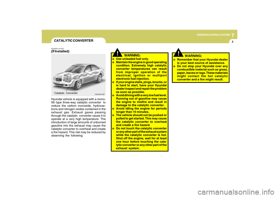
CATALYTIC CONVERTERH020A01A-AAT(If Installed)Hyundai vehicle is equipped with a mono-
lith type three-way catalytic converter to
reduce the carbon monoxide, hydrocar-
bons and nitrogen oxides contained in the
exhaust gas. Exhaust gases passing
through the catalytic converter cause it to
operate at a very high temperature. The
introduction of large amounts of unburned
gasoline into the exhaust may cause the
catalytic converter to overheat and create
a fire hazard. This risk may be reduced by
observing the following:Catalytic Converter
WARNING:
o Use unleaded fuel only.
o Maintain the engine in good operating
condition. Extremely high catalytic
converter temperatures can result
from improper operation of the
electrical, ignition or multiport
electronic fuel injection.
o If your engine stalls, pings, knocks, or
is hard to start, have your Hyundai
dealer inspect and repair the problem
as soon as possible.
o Avoid driving with a very low fuel level.
Running out of gasoline may cause
the engine to misfire and result in
damage to the catalytic converter.
o Avoid idling the engine for periods
longer than 10 minutes.
o The vehicle should not be pushed or
pulled to get started. This may cause
the catalytic converter to overheat
and create a fire hazard.
o Do not touch the catalytic converter
or any other part of the exhaust system
while the catalytic converter is hot.
Shut off the engine, wait for at least
one hour before touching the cata-
lytic converter or any other part of the
exhaust system.
H020A01NF
o Remember that your Hyundai dealer
is your best source of assistance.
o Do not stop your Hyundai over any
combustible material such as grass,
paper, leaves or rags. These materials
might contact the hot catalytic
converter and a fire might result.
WARNING:
Page 262 of 286
8CONSUMER INFORMATION, REPORTING SAFETY DEFECTS & BINDING ARBITRATION OF WARRANTY CLAIMS4
!
CAUTION:
Always observe the following:
o Check pressures when the tires
are cold. (After the vehicle has
been parked for at least three hours
or hasn't been driven more than 1
mile (1.6 km) since starting up.)
o Check the pressure of your spare
tire each time you check the pres-
sure of other tires.
o Worn, old tires can cause acci-
dents. If your tread is badly worn,
or if your tires have been dam-
aged, replace them.
!
NOTE:
o Underinflation also results in ex-
cessive wear, poor handling and
reduced fuel economy. Wheel de-
formation also is possible. Keep
your tire pressures at the proper
levels. If a tire frequently needs
refilling, have it checked by your
Hyundai Dealer.
o Overinflation produces a harsh
ride, excessive wear at the center
of the tire tread, and a greater
possibility of damage from road
hazards.
WARNING:
Overinflation or underinflation can
reduce the tire life, adversely affect
vehicle handling, and lead to sud-
den tire failure. This could rusult in
loss of vehicle control and potential
injury.
!
WARNING:
o Inspect your tires frequently for
proper inflation as well as wear
and damage. Always use a tire
pressure gauge.
o Tires with too much or too little
pressure wear unevenly causing
poor handling, loss of vehicle
control, and sudden tire failure
leading to accidents, injuries, and
even death. The recommended
cold tire pressure for your vehicle
can be found in this manual and
on the tire label located on the
driver's side of the center pillar.
o Worn tires can cause accidents.
Replace tires that are worn, show
uneven wear, or are damaged. See
page 8-11.
o Remember to check the pressure
of your spare tire. Hyundai recom-
mends that you check the spare
every time you check the pressure
of the other tires on your vehicle.
Page 265 of 286
8
CONSUMER INFORMATION, REPORTING SAFETY DEFECTS & BINDING ARBITRATION OF WARRANTY CLAIMS
7
6. Maximum load rating
This number indicates the maximum
load in kilograms and pounds that
can be carried by the tire. When
replacing the tires on the vehicle,
always use a tire that has the same
load rating as the factory installed
tire.
7. Uniform Tire Quality Grading
(UTQG):
Tire manufacturers are required to
grade tires based on three perfor-
mance factors: treadwear, traction
and temperature resistance. For more
information, see Uniform Tire Qual-
ity Grading on page 8-14.
I030D01JM-AATTIRE TERMINOLOGY AND DEFINI-
TIONS
Air Pressure: The amount of air inside
the tire pressing outward on the tire. Air
pressure is expressed in pounds per
square inch (psi) or kilopascal (kPa).
Accessory Weight: This means the
combined weight of optional accesso-
ries. Some examples of optional ac-
cessories are, automatic transmission,
power seats, and air conditioning.
Aspect Ratio: The relationship of a
tire's height to its width.
Belt: A rubber coated layer of cords that
is located between the plies and the
tread. Cords may be made from steel or
other reinforcing materials.
Bead: The tire bead contains steel
wires wrapped by steel cords that hold
the tire onto the rim.
Bias Ply Tire: A pneumatic tire in which
the plies are laid at alternate angles
less than 90 degrees to the centerline of
the tread.Cold Tire Pressure: The amount of air
pressure in a tire, measured in pounds
per square inch (psi) or kilopascals
(kPa) before a tire has built up heat from
driving.
Curb Weight: This means the weight of
a motor vehicle with standard and op-
tional equipment including the maxi-
mum capacity of fuel, oil and coolant,
but without passengers and cargo.
DOT Markings: A code molded into the
sidewall of a tire signifying that the tire
is in compliance with the U.S. Depart-
ment of Transportation motor vehicle
safety standards. The DOT code in-
cludes the Tire Identification Number
(TIN), an alphanumeric designator which
can also identify the tire manufacturer,
production plant, brand and date of
production.
GVWR: Gross Vehicle Weight Rating
GAWR FRT: Gross Axle Weight Rating
for the front Axle.
GAWR RR: Gross Axle Weight Rating
for the rear axle.
Page 277 of 286
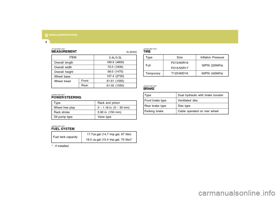
9
VEHICLE SPECIFICATIONS2
J010A03NF-AATMEASUREMENTJ060A01NF-AATFUEL SYSTEMJ020A01NF-AATPOWER STEERING
J030A03NF-AATTIRE
in.(mm)
Fuel tank capacity
17.7us.gal (14.7 imp.gal, 67 liter)
18.5 us.gal (15.4 imp.gal, 70 liter)* ITEM
J050A01NF-AATBRAKE
Dual hydraulic with brake booster
Ventilated disc
Disc type
Cable operated on rear wheel Type
Front brake type
Rear brake type
Parking brake
Type
Wheel free play
Rack stroke
Oil pump typeRack and pinion
0 ~ 1.18 in. (0 ~ 30 mm)
5.90 in. (150 mm)
Vane type
2.4L/3.3L
189.9 (4800)
72.0 (1830)
58.0 (1475)
107.4 (2730)
61.61 (1565)
61.02 (1550) Overall length
Overall width
Overall height
Wheel base
Wheel tread
Front
Rear
Inflation Pressure
32PSI (220kPa)
60PSI (420kPa)
Type
Full
TemporarySize
P215/60R16
P215/55R17
T125/80D16
* : if installed
Page 283 of 286

10
INDEX
4
Fuel
Capacity............................................................................ 9-2
Gauge..............................................................................1-55
Recommendations............................................................ 1-2
Fuel Filler Lid
Remote release ..............................................................1-85
Fuse Panel Description .....................................................6-37
Fuses..................................................................................6-22
G
General Checks ................................................................... 6-4
Glove Box ...........................................................................1-73
H
Hazard Warning System ....................................................1-65
Headlight
Aiming adjustment ..........................................................6-27
Replacement...................................................................6-28
Switch..............................................................................1-61
Heating and Cooling Control ............................................1-96
Heating and Ventilation
Air flow control ................................................... 1-98, 1-108
Air intake control switch ..................................... 1-99, 1-107
Bi-level heating .............................................................1-100
Defrosting/Defogging....................................................1-103
Fan speed control (Blower Control) .................. 1-97, 1-107
Temperature control .......................................................1-97
High-Mounted Rear Stop Light .........................................1-85
Hood Release ....................................................................1-87
Horn....................................................................................1-90I
Ignition Switch ...................................................................... 2-3
Instrument Cluster and Indicator Lights ............................1-48
Instrument Panel Light Control (Rheostat) .......................1-66
Interior Light .......................................................................1-72
Intermittent Wiper ...............................................................1-64
J
Jump Starting ....................................................................... 3-3
K
Key ........................................................................................ 1-3
If you lose your keys ......................................................3-18
Positions............................................................................ 2-3
L
Light Bulb Watages ............................................................6-36
Light Bulbs Replacement ..................................................6-28
Lubrication Chart .................................................................. 9-4
M
Maintenance Intervals
Explanation of scheduled maintenance items ................ 5-7
Maintenance under severe usage conditions ................. 5-6
Scheduled maintenance .................................................. 5-4
Service requirements ........................................................ 5-2
Mirrors
Day/night inside rearview ...............................................1-76
Homelink mirror ..............................................................1-77
Outside rearview .............................................................1-75
Outside rearview mirror heater ......................................1-76