2009 Hyundai Sonata ECU
[x] Cancel search: ECUPage 196 of 286
3
WHAT TO DO IN AN EMERGENCY
15
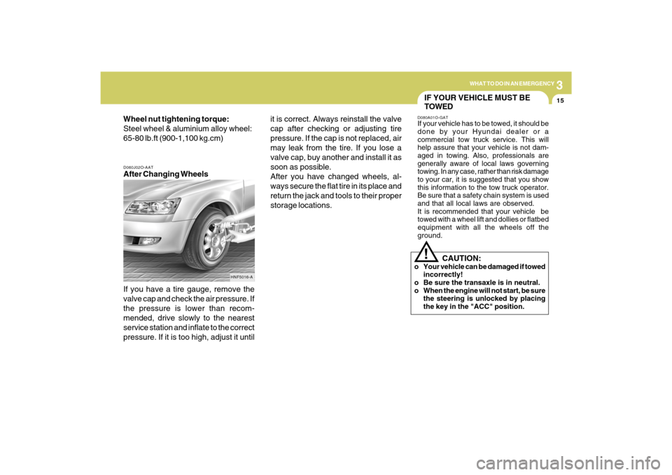
D060J02O-AATAfter Changing Wheels
If you have a tire gauge, remove the
valve cap and check the air pressure. If
the pressure is lower than recom-
mended, drive slowly to the nearest
service station and inflate to the correct
pressure. If it is too high, adjust it until Wheel nut tightening torque:
Steel wheel & aluminium alloy wheel:
65-80 lb.ft (900-1,100 kg.cm)
HNF5016-A
it is correct. Always reinstall the valve
cap after checking or adjusting tire
pressure. If the cap is not replaced, air
may leak from the tire. If you lose a
valve cap, buy another and install it as
soon as possible.
After you have changed wheels, al-
ways secure the flat tire in its place and
return the jack and tools to their proper
storage locations.
IF YOUR VEHICLE MUST BE
TOWEDD080A01O-GATIf your vehicle has to be towed, it should be
done by your Hyundai dealer or a
commercial tow truck service. This will
help assure that your vehicle is not dam-
aged in towing. Also, professionals are
generally aware of local laws governing
towing. In any case, rather than risk damage
to your car, it is suggested that you show
this information to the tow truck operator.
Be sure that a safety chain system is used
and that all local laws are observed.
It is recommended that your vehicle be
towed with a wheel lift and dollies or flatbed
equipment with all the wheels off the
ground.!
CAUTION:
o Your vehicle can be damaged if towed
incorrectly!
o Be sure the transaxle is in neutral.
o When the engine will not start, be sure
the steering is unlocked by placing
the key in the "ACC" position.
Page 212 of 286
5
VEHICLE MAINTENANCE REQUIREMENTS
7
F060D01A-AATo Fuel Lines, Fuel Hoses and Con-
nectionsCheck the fuel lines, fuel hoses and con-
nections for leakage and damage. Have a
trained technician replace any damaged
or leaking parts immediately.F060B01NF-GATo Drive BeltsInspect all drive belts for evidence of cuts,
cracks, excessive wear or oil saturation
and replace if necessary. Drive belts should
be checked periodically for proper tension.
F060M01A-AATo Engine Oil and FilterThe engine oil and filter should be changed
at the intervals specified in the
maintenance schedule. If the car is being
driven in severe conditions, more frequent
oil and filter changes are required.F060C01A-AATo Fuel FilterA clogged filter can limit the speed at which
the vehicle may be driven, damage the
emission system and cause hard starting.
If an excessive amount of foreign matter
accumulates in the fuel tank, the filter may
require replacement more frequently.
After installing a new filter, run the engine
for several minutes, and check for leaks at
the connections. Fuel filters should be
installed by trained technicians.
F060F01A-AATo Vacuum, Crankcase Ventilation
HosesInspect the surface of hoses for evidence
of heat and/or mechanical damage. Hard
and brittle rubber, cracking, tears, cuts,
abrasions, and excessive swelling indicate
deterioration. Particular attention should
be paid to examine those hose surfaces
nearest to high heat sources, such as the
exhaust manifold.
Inspect the hose routing to assure that the
hoses do not come in contact with any heat
source, sharp edges or moving component
which might cause heat damage or
mechanical wear. Inspect all hose
connections, such as clamps and
couplings, to make sure they are secure,
and that no leaks are present. Hoses should
be replaced immediately if there is any
evidence of deterioration or damage.
EXPLANATION OF SCHEDULED MAINTENANCE ITEMS
Page 225 of 286
6
DO-IT-YOURSELF MAINTENANCE
10
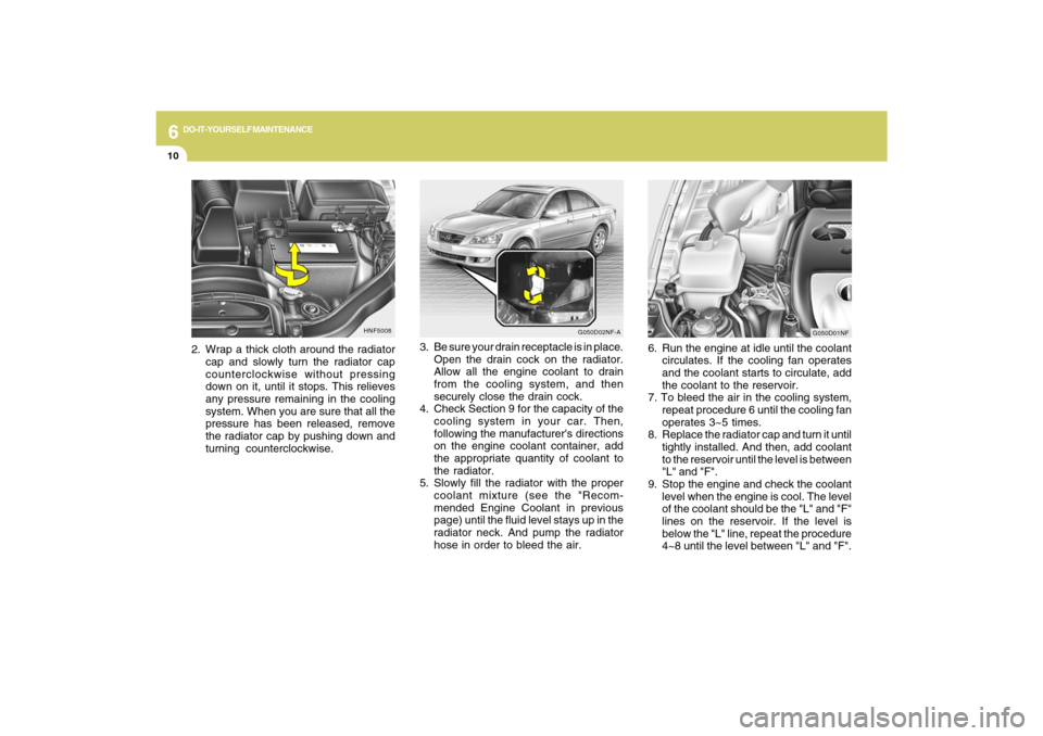
3. Be sure your drain receptacle is in place.
Open the drain cock on the radiator.
Allow all the engine coolant to drain
from the cooling system, and then
securely close the drain cock.
4. Check Section 9 for the capacity of the
cooling system in your car. Then,
following the manufacturer's directions
on the engine coolant container, add
the appropriate quantity of coolant to
the radiator.
5. Slowly fill the radiator with the proper
coolant mixture (see the "Recom-
mended Engine Coolant in previous
page) until the fluid level stays up in the
radiator neck. And pump the radiator
hose in order to bleed the air.
HNF5008
2. Wrap a thick cloth around the radiator
cap and slowly turn the radiator cap
counterclockwise without pressing
down on it, until it stops. This relieves
any pressure remaining in the cooling
system. When you are sure that all the
pressure has been released, remove
the radiator cap by pushing down and
turning counterclockwise.
G050D02NF-A
G050D01NF
6. Run the engine at idle until the coolant
circulates. If the cooling fan operates
and the coolant starts to circulate, add
the coolant to the reservoir.
7. To bleed the air in the cooling system,
repeat procedure 6 until the cooling fan
operates 3~5 times.
8. Replace the radiator cap and turn it until
tightly installed. And then, add coolant
to the reservoir until the level is between
"L" and "F".
9. Stop the engine and check the coolant
level when the engine is cool. The level
of the coolant should be the "L" and "F"
lines on the reservoir. If the level is
below the "L" line, repeat the procedure
4~8 until the level between "L" and "F".
Page 253 of 286
6
DO-IT-YOURSELF MAINTENANCE
38
1
2
3
4
5
6
7
8
9
10
11
12
13
14
15
16
17
18
19
20
21
22
23
24
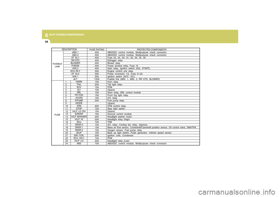
HORN
TAIL
ECU
IG1
DRL
FR FOG
A/CON
F/PUMP
DIODE
ATM
STOP
H/LP LO RH
S/ROOF
H/LP WASHER
H/LP HI
ECU
SNSR.3
SNSR.1
SNSR.2
B/UP
IGN COIL
ECU (IG1)
H/LP LO
ABS
PROTECTED COMPONENTS
ABS/ESC control module, Multipurpose check connector
ABS/ESC control module, Multipurpose check connector
Fuse 23, 24, 30, 31, 32, 33, 34, 35
Defogger relay
Blower relay
Power window relay, Fuse 16
Start relay, Ignition switch (IG2, START)
Engine control unit relay
Power connector 1/2, Fuse 21,22
Ignition switch (ACC, IG1)
Fusible Iink (ABS. 1, ABS. 2, RR HTD, BLOWER)
Horn relay
Tail light relay
PCM
(Spare)
Siren relay, DRL control module
Front fog light relay
A/C relay
Fuel pump relay
(Spare)
ATM control relay
Stop light switch
(Spare)
Sunroof control module
Headlight washer motor
Headlight relay (High)
TCM
A/C relay, Cooling fan relay, Injectors
Mass air flow sensor, Crankshaft/Camshaft position sensor, Oil control valve, SMATRA
Oxygen sensor, Fuel pump relay
Back up light switch, Pulse generator, Vehicle speed sensor
Ignition coils, Condenser
PCM
Headlight relay (Low)
ABS/ESC control module, Multipurpose check connector
ABS.1
ABS.2
I/P B+1
RR HTD
BLOWER
P/WDW
IGN.2
ECU RLY
I/P B+2
IGN.1
ALTFUSE RATING
40A
20A
40A
40A
40A
40A
40A
30A
30A
30A
150A
15A
20A
10A
10A
15A
15A
10A
20A
-
20A
15A
15A
15A
20A
20A
10A
10A
15A
15A
10A
20A
10A
20A
10A
DESCRIPTION
FUSIBLE
LINK
FUSE
Page 281 of 286
10
INDEX
2
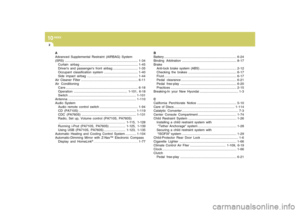
A
Advanced Supplemental Restraint (AIRBAG) System
(SRS)..................................................................................1-34
Curtain airbag .................................................................1-45
Driver's and passenger's front airbag ............................1-35
Occupant classification system ......................................1-40
Side impact airbag .........................................................1-44
Air Cleaner Filter ................................................................6-11
Air Conditioning
Care.................................................................................6-18
Operation............................................................ 1-101, 6-18
Switch............................................................................1-101
Antenna ............................................................................1-110
Audio System
Audio remote control switch ...........................................1-94
CD (PA710S) ................................................................1-119
CDC (PA760S) .............................................................1-131
Radio, Set up, Volume control (PA710S, PA760S)
........................................................................... 1-115, 1-128
Running i-Pod (PA710S, PA760S) .................. 1-125, 1-139
Using USB (PA710S, PA760S) ........................ 1-123, 1-135
Automatic Heating and Cooling Control System ............1-104
Automatic-Dimming Mirror with Z-Nav™ Electronic Compass
Display and HomeLink
®
......................................................................................
1-77B
Battery .................................................................................6-24
Binding Arbitration .............................................................8-17
Brake
Anti-lock brake system (ABS) .........................................2-12
Checking the brakes ......................................................6-17
Fluid.................................................................................6-17
Pedal clearance ..............................................................6-21
Pedal free-play ...............................................................6-20
Practices..........................................................................2-15
Breaking-In your New Hyundai ........................................... 1-3
C
California Perchlorate Notice ............................................5-10
Care of Discs ....................................................................1-114
Catalytic Converter ............................................................... 7-3
Center Console Compartment ...........................................1-74
Child Restraint System ......................................................1-26
Installing a child restraint system with
"Tether Anchorage" system ...........................................1-28
Securing a child restraint system with
"ISOFIX" system .............................................................1-29
Child-Protector Rear Door Lock .......................................... 1-6
Cigarette Lighter ................................................................1-66
Climate Control Air Fiter ........................................ 1-109, 6-19
Clock...................................................................................1-66
Clutch
Pedal free-play ...............................................................6-21