2009 Hyundai Sonata controls
[x] Cancel search: controlsPage 95 of 286
1FEATURES OF YOUR HYUNDAI82
!
handheld transmitter every two seconds
until the frequency signal has been learned.
The indicator light will flash slowly and
then rapidly after several seconds upon
successful training.
Operating HomeLink
®
To operate, simply press and release the
programmed HomeLink
® button. Activation
will now occur for the trained device (i.e.
garage door opener, gate operator, security
system, entry door lock, home/office
lighting, etc.). For convenience, the hand-
held transmitter of the device may also be
used at any time.
Reprogramming a Single HomeLink
® But-
ton
To program a new device to a previously
trained HomeLink
® button, follow these
steps:
1. Press and hold the desired HomeLink
®
button. Do NOT release until step 4 has
been completed.
2. When the indicator light begins to flash
slowly (after 20 seconds), position the
handheld transmitter 1 to 3 inches away
from the HomeLink
® surface.
3. Press and hold the handheld transmitter
button. The HomeLink
® indicator light
will flash, first slowly and then rapidly.4. When the indicator light begins to flash
rapidly, release both buttons.
5. Press and hold the just-trained
HomeLink
® button and observe the red
Status Indicator LED. If the indicator
light stays on constantly, programming
is complete and your new device should
activate.
Erasing HomeLink
® Buttons
Individual buttons cannot be erased.
However, to erase all three programmed
buttons:
1. Press and hold the two outer HomeLink
®
buttons until the indicator light begins to
flash-after 20 seconds.
2. Release both buttons. Do not hold for
longer than 30 seconds.
The Integrated HomeLink
® Wireless
Control System is now in the training (learn)
mode and can be programmed at any time
following the appropriate steps in the
Programming sections above.
FCC ID: NZLZTVHL3
IC: 4112A-ZTVHL3This device complies with Part 15 FCC
Rules. Operation is subject to the following
two conditions: (1) this device may not
cause harmful interference, and (2) this
device must accept any interference
received, including interference that may
cause undesired operation.
WARNING:
The transceiver has been tested and
complies with FCC and Industry Canada
rules. Changes or modifications not
expressly approved by the party
responsible for compliance could void
the user's authority to operate the
device.
NVS
® is a registered trademark and Z-
Nav™ is a trademark of the Gentex
Corporation, Zeeland, Michigan.
HomeLink
® is a registered trademark
owned by Johnson Controls, Incorporated,
Milwaukee, Wisconsin.
Page 111 of 286
1FEATURES OF YOUR HYUNDAI98
MAX A/C-Level (B, D) *
1
Air is discharged through the face level
vents.
If the "MAX A/C" mode is selected, the A/C
will turn on automatically and
"Recirculation" mode will be activated.
*1 : See page 1-96
Floor-Level (C, E, A, D) *
1
Air is discharged through the floor vents,
windshield defroster nozzle, side defroster
nozzle and side ventilator.
If the "Floor" mode is selected, the "Fresh"
mode will be activated.
Floor-Defrost Level (A, C, E, D) *
1
Air is discharged through the windshield
defroster nozzle, the floor vents, side
defroster nozzle and side ventilator.
If the "Floor-Defrost" mode is selected,
"Fresh" mode will be activated.
Defrost-Level (A, D) *
1
Air is discharged through the windshield
defroster nozzle, side defroster nozzle and
side ventilator.
If the "Defrost" mode is selected, the "Fresh"
mode will be activated to improve
windshield defrosting.
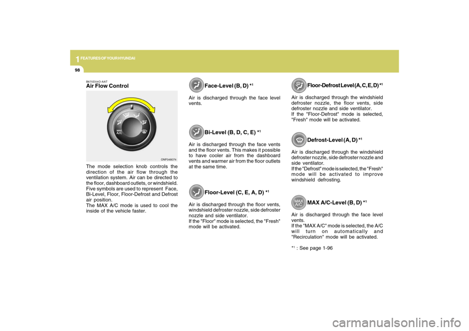
B670D04O-AATAir Flow ControlThe mode selection knob controls the
direction of the air flow through the
ventilation system. Air can be directed to
the floor, dashboard outlets, or windshield.
Five symbols are used to represent Face,
Bi-Level, Floor, Floor-Defrost and Defrost
air position.
The MAX A/C mode is used to cool the
inside of the vehicle faster.
Face-Level (B, D) *
1
Air is discharged through the face level
vents.
Bi-Level (B, D, C, E) *
1
Air is discharged through the face vents
and the floor vents. This makes it possible
to have cooler air from the dashboard
vents and warmer air from the floor outlets
at the same time.
ONF048074
Page 113 of 286
1FEATURES OF YOUR HYUNDAI
100
VENTILATION
B700A02A-AATBI-LEVEL HEATING
B710A01A-AAT
Your Hyundai is equipped with bi-level
heating controls. This makes it possible to
have cooler air from the dashboard vents
and warmer air from the floor outlets at the
same time. To use this feature:
o Set the air intake control switch to the
fresh air ( ) position.
o Set the air flow control at the bi-level ( )
position.
o Adjust the fan speed control to the
desired speed.
o Set the temperature control between
"Cool" and "Warm".To operate the ventilation system:
o Set the air intake control to the fresh air
( ) position.
o To direct all intake air to the dashboard
vents, set the airflow control to the face
( ) position.
o Adjust the fan speed control to the
desired speed.
o Set the temperature control between
"Cool" and "Warm".
For normal heating operation, set the air
flow control to the floor ( ) position. (The
"Fresh" mode will be activated.)
For faster heating, the air intake control
switch should be set in the recirculate ( )
position.
If the windows fog up, set the air flow
control to the defrost ( ) position (The A/
C will turn on automatically and "Fresh"
mode will be activated.)
For maximum heat, move the temperature
control to "Warm".HEATING CONTROLSB690A01O-AAT
Page 117 of 286
1FEATURES OF YOUR HYUNDAI
104
AUTOMATIC HEATING AND COOLING CONTROL SYSTEMB970A01Y-AAT(If lnstalled)Your Hyundai is equipped with an auto-
matic heating and cooling control system
controlled by simply setting the desired
temperature.
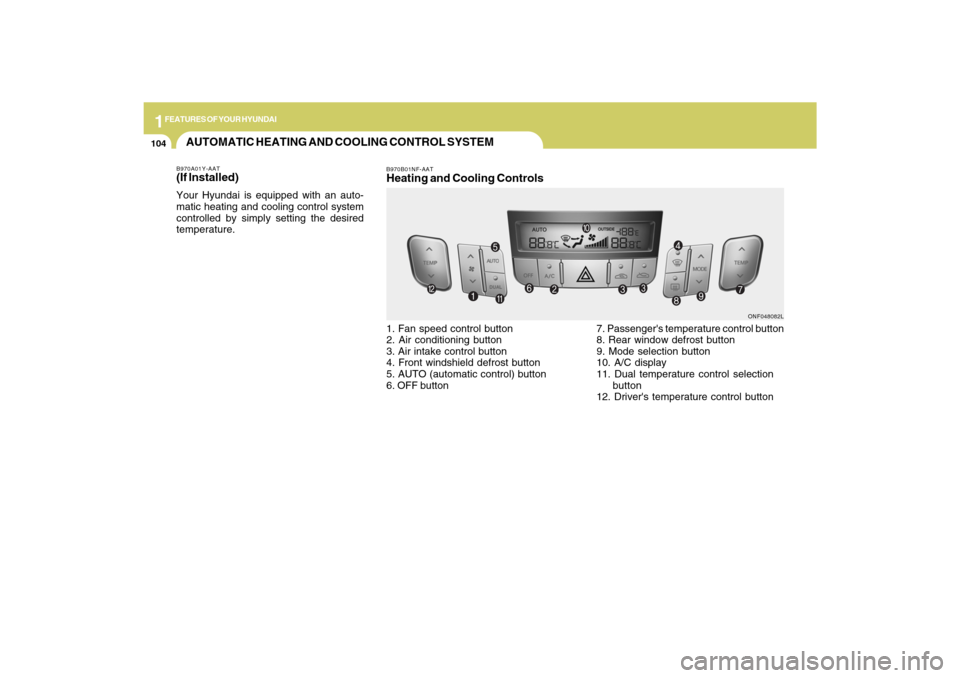
B970B01NF-AATHeating and Cooling Controls1. Fan speed control button
2. Air conditioning button
3. Air intake control button
4. Front windshield defrost button
5. AUTO (automatic control) button
6. OFF button7. Passenger's temperature control button
8. Rear window defrost button
9. Mode selection button
10. A/C display
11. Dual temperature control selection
button
12. Driver's temperature control button
ONF048082L
Page 118 of 286
1
FEATURES OF YOUR HYUNDAI
105105
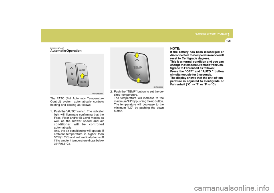
B970C01NF-AATAutomatic OperationThe FATC (Full Automatic Temperature
Control) system automatically controls
heating and cooling as follows:
1. Push the "AUTO" switch. The indicator
light will illuminate confirming that the
Face, Floor and/or Bi-Level modes as
well as the blower speed and air
conditioner will be controlled
automatically.
And, the air conditioning will operate if
ambient temperature is higher than
35°F(1.5°C) and automatically turns off
if the ambient temperature drops below
33°F(0.6°C).2. Push the "TEMP" button to set the de-
sired temperature.
The temperature will increase to the
maximum "HI" by pushing the up button.
The temperature will decrease to the
minimum "LO" by pushing the down
button.
NOTE:If the battery has been discharged or
disconnected, the temperature mode will
reset to Centigrade degrees.
This is a normal condition and you can
change the temperature mode from Cen-
tigrade to Fahrenheit as follows;
Press the "OFF" and "AUTO " button
simultaneously for 3 seconds.
The display shows that the unit of tem-
perature is adjusted to Centigrade or
Fahrenheit (°C
→ →→ →
→ °F or °F
→ →→ →
→ °C).
ONF048083NONF048086
Page 165 of 286
2
DRIVING YOUR HYUNDAI
12
!
ANTI-LOCK BRAKE SYSTEM
(ABS)C120A01FC-AATThe Anti-Lock Brake System (ABS) is
designed to prevent wheel lock-up during
sudden braking or on hazardous road
surfaces. The ABS control module monitors
the wheel speed and controls the pressure
applied to each brake. Thus, in emergency
situations or on slick roads, ABS will
increase vehicle control during braking.NOTE:o A click sound may be heard in the
engine compartment when the ve-
hicle begins to move after the engine
is started. These conditions are nor-
mal and indicate that the anti-lock
brake system or Electronic Stability
Control is functioning properly.
o During ABS or ESC operation, a pul-
sation may be felt in the brake pedal
when the brakes are applied. Also, a
noise may be heard in the engine
compartment while braking. These
conditions are normal and indicate
that the anti-lock brake system or
Electronic Stability Control System is
functioning properly.
Setting the driver's position1) Be sure the parking brake is engaged.
2) Move the accelerator and brake pedals
to the front most position by pushing the
" " portion of the switch.
3) Adjust the seat position and the steering
wheel angle properly.
4) Move the pedals toward you until you
can fully depress the brake pedal by
pushing the " " portion of the switch.
5) Depress the pedals a few times to get
used to the feel after adjusting.
WARNING:
o Adjust the pedals after parking the
vehicle on level ground. Never attempt
to adjust the pedals while the vehicle
is moving.
o Never adjust the pedals with your foot
on the accelerator pedal as this may
result in increasing the engine speed
and acceleration.
o Make sure that you can fully depress
the brake pedal before driving.
Otherwise, you may not be able to
hold down the brake pedal firmly in an
emergency stop.
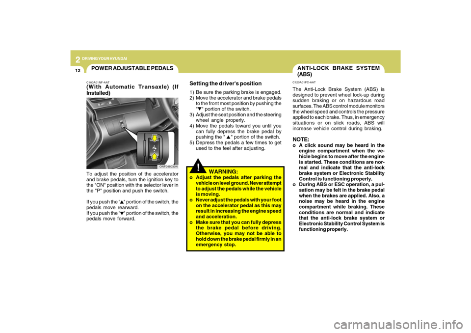
POWER ADJUSTABLE PEDALSC100A01NF-AAT(With Automatic Transaxle) (If
Installed)To adjust the position of the accelerator
and brake pedals, turn the ignition key to
the "ON" position with the selector lever in
the "P" position and push the switch.
If you push the " " portion of the switch, the
pedals move rearward.
If you push the " " portion of the switch, the
pedals move forward.
ONF048030N
Page 257 of 286

7
EMISSION CONTROL SYSTEMS2
EMISSION CONTROL
SYSTEMS
H010B01A-AAT1. Crankcase Emission Control Sys-
temThe positive crankcase ventilation system
is employed to prevent air pollution caused
by blow-by gases being emitted from the
crankcase. This system supplies fresh
filtered air to the crankcase through the air
intake hose. Inside the crankcase, the fresh
air mixes with blow-by gases, which then
pass through the PCV valve into the
induction system.
CanisterFuel vapors generated inside the fuel tank
are absorbed and stored in the onboard
canister. When the engine is running, the
fuel vapors absorbed in the canister are
drawn into the surge tank through the
purge control solenoid valve.Purge Control Solenoid Valve (PCSV)The purge control solenoid valve is
controlled by the Engine Control Module
(ECM); when the engine coolant
temperature is low during idling, the PCSV
closes so that evaporated fuel is not taken
into the engine. After the engine warms-up
during ordinary driving, the PCSV opens
to introduce evaporated fuel to the engine.H010D01A-AAT3. Exhaust Emission Control
SystemThe Exhaust Emission Control System is a
highly effective system which controls
exhaust emissions while maintaining good
vehicle performance.
H010A01NF-AATYour Hyundai is equipped with an emission
control system to meet all emission
regulations.
There are three emission control systems
which are as follows.
(1) Crankcase emission control system
(2) Evaporative emission control system
(3) Exhaust emission control system
In order to assure the proper function of the
emission control systems, it is
recommended that you have your car
inspected and maintained by an authorized
Hyundai dealer in accordance with the
maintenance schedule in this manual.
Caution for the Inspection and Mainte-
nance Test With Electronic Stability
Control (ESC) system
o To prevent the vehicle from misfiring
during dynamometer testing, turn the
Electronic Stability Control (ESC) sys-
tem off by pressing the ESC switch.
o After dynamometer testing is com-
pleted, turn the ESC system back on
by pressing the ESC switch again.
H010C01S-AAT2. Evaporative Emission Control (In-
cluding ORVR: Onboard Refueling
Vapor Recovery) SystemThe Evaporative Emission Control System
is designed to prevent fuel vapors from
escaping into the atmosphere.
(The ORVR system is designed to allow
the vapors from the fuel tank to be loaded
into a canister while refueling at the gas
station, preventing the escape of fuel
vapors into the atmosphere.)