Page 299 of 340
Maintenance
56
7
4. Push in a new fuse of the same rating,
and make sure it fits tightly in the clips.
If it fits loosely, consult an authorised
HYUNDAI dealer.
G210201AFD-EA Main fuse
If the main fuse is blown, it must be
removed as follows:
1. Disconnect the negative battery cable.
2. Remove the nuts shown in the pictureabove.
3. Replace the fuse with a new one of the same rating.
4. Reinstall in the reverse order of removal.✽✽ NOTICE
If the main fuse is blown, consult an
authorised HYUNDAI dealer.
CAUTION
After checking the fuse box in the engine compartment, securely install the fuse box cover. If not,
electrical failures may occur from water leaking in.
ONF078038
Page 300 of 340
757
Maintenance
✽✽NOTICE
Not all fuse panel descriptions in this
manual may be applicable to your vehi-cle. It is accurate at the time of printing.When you inspect the fuse box on your
vehicle, refer to the fuse box label.G210300ANF-EA
Fuse/Relay panel description
Inside the fuse/relay box covers, you can find the fuse/relay label describing fuse/relay
name and capacity.
Engine compartmentONF078021R/ONF078022/ONF078023
Diesel only
Driver’s side panel
Page 303 of 340
Maintenance
60
7
Engine compartment
Description Fuse rating Protected component
ABS.1 40A ABS/ESP control module, Multipurpose check connector
ABS.2 20A ABS/ESP control module, Multipurpose check connector
I/P B+1 40A Fuse 23, 24, 30, 31, 32, 33, 34, 35
RR HTD 40A Defogger relay
BLOWER 40A Blower relay
Fusible link P/WDW 40A Power window relay, Fuse 16 IGN.2 40A Start relay, Ignition switch (IG2, START)
ECU RLY 30A Engine control unit relay
I/P B+2 30A Power connector 1/2, Fuse 21,22
IGN.1 30A Ignition switch (ACC, IG1)
ALT 150A Fusible Iink (ABS. 1, ABS. 2, RR HTD, BLOWER)
1 HORN 15A Horn relay
2 TAIL 20A Tail light relay
3 ECU 10A PCM
4 IG1 10A DSL TCU
5 DRL 15A Siren relay, DRL control module
6 FR FOG 15A Front fog light relay
Fuse 7 A/CON 10A A/C relay 8 F/PUMP 20A Fuel pump relay
9 DIODE - (Spare)
10 ATM 20A ATM control relay, TCU
11 STOP 15A Stop light switch
12 H/LP LO RH 15A (Spare)
13 S/ROOF 15A Sunroof control module
Page 304 of 340
761
Maintenance
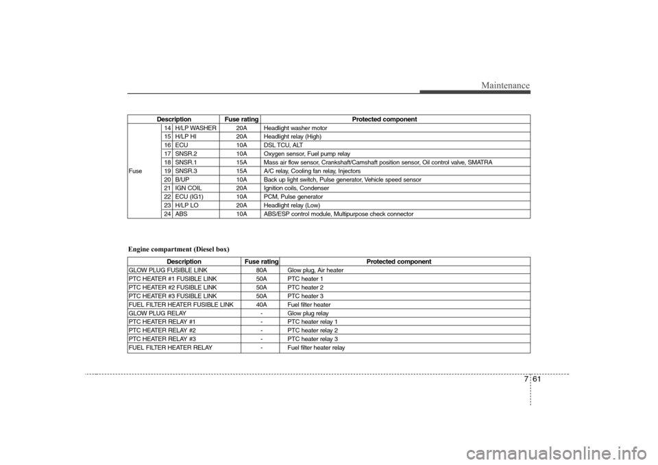
Description Fuse rating Protected component14 H/LP WASHER 20A Headlight washer motor
15 H/LP HI 20A Headlight relay (High)
16 ECU 10A DSL TCU, ALT
17 SNSR.2 10A Oxygen sensor, Fuel pump relay
18 SNSR.1 15A Mass air flow sensor, Crankshaft/Camshaft position sensor, Oil control valve, SMATRA
Fuse 19 SNSR.3 15A A/C relay, Cooling fan relay, Injectors 20 B/UP 10A Back up light switch, Pulse generator, Vehicle speed sensor
21 IGN COIL 20A Ignition coils, Condenser
22 ECU (IG1) 10A PCM, Pulse generator
23 H/LP LO 20A Headlight relay (Low)
24 ABS 10A ABS/ESP control module, Multipurpose check connector
Description Fuse rating Protected component
GLOW PLUG FUSIBLE LINK 80A Glow plug, Air heater
PTC HEATER #1 FUSIBLE LINK 50A PTC heater 1
PTC HEATER #2 FUSIBLE LINK 50A PTC heater 2
PTC HEATER #3 FUSIBLE LINK 50A PTC heater 3
FUEL FILTER HEATER FUSIBLE LINK 40A Fuel filter heater
GLOW PLUG RELAY - Glow plug relay
PTC HEATER RELAY #1 - PTC heater relay 1
PTC HEATER RELAY #2 - PTC heater relay 2
PTC HEATER RELAY #3 - PTC heater relay 3
FUEL FILTER HEATER RELAY - Fuel filter heater relay
Engine compartment (Diesel box)
Page 311 of 340
Maintenance
68
7
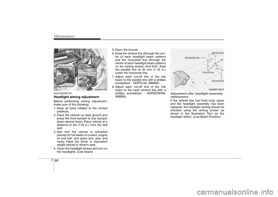
G221000ANF-EA Headlight aiming adjustment
Before performing aiming adjustment,
make sure of the following.
1. Keep all tyres inflated to the correct
pressure.
2. Place the vehicle on level ground and press the front bumper & rear bumper
down several times. Place vehicle at adistance of 3m (118 in.) from the test
wall.
3. See that the vehicle is unloaded (except for full levels of coolant, engine
oil and fuel, and spare tyre, jack, and
tools). Have the driver or equivalent
weight placed in driver's seat.
4. Clean the headlight lenses and turn on the headlights. (Low beam) 5. Open the bonnet.
6. Draw the vertical line (through the cen-
tre of each headlight beam pattern)
and the horizontal line (through the
centre of each headlight beam pattern)
on the aiming screen. And then, draw
the parallel line at 30 mm (1.18 in.)
under the horizontal line.
7. Adjust each cut-off line of the low beam to the parallel line with a phillips
screwdriver - VERTICAL AIMING.
8. Adjust each cut-off line of the low beam to the each vertical line with a
phillips screwdriver - HORIZONTALAIMING.Adjustment after headlight assembly
replacement
If the vehicle has had front body repair
and the headlight assembly has beenreplaced, the headlight aiming should be
checked using the aiming screen as
shown in the illustration. Turn on the
headlight switch. (Low Beam Position)
G290A01NF
Vertical aiming
Horizontal aiming
G290B01JM-D H
H L30 mm
W
Horizontal line
Vertical line
“P”
Ground line
Cut-off line
Page 313 of 340
Maintenance
70
7
APPEARANCE CARE
Exterior care
G230101AUN
Exterior general caution
It is very important to follow the label
directions when using any chemical
cleaner or polish. Read all warning andcaution statements that appear on thelabel.
G230102BUN-EA
Finish maintenance
Washing
To help protect your vehicle’s finish from
rust and deterioration, wash it thoroughlyand frequently at least once a month with
lukewarm or cold water.
If you use your vehicle for off-road driv-
ing, you should wash it after each off-
road trip. Pay special attention to the
removal of any accumulation of salt, dirt,
mud, and other foreign materials. Make
sure the drain holes in the lower edges of
the doors and rocker panels are keptclear and clean. Insects, tar, tree sap, bird droppings,
industrial pollution and similar deposits
can damage your vehicle’s finish if not
removed immediately.
Even prompt washing with plain water
may not completely remove all these
deposits. A mild soap, safe for use on
painted surfaces, may be used.
After washing, rinse the vehicle thor-
oughly with lukewarm or cold water. Do
not allow soap to dry on the finish.
WARNING -
Wet brakes
After washing the vehicle, test the
brakes while driving slowly to see if
they have been affected by water. If
braking performance is impaired,
dry the brakes by applying them
lightly while maintaining a slow for-
ward speed.
CAUTION
Do not use strong soap, chemical detergents or hot water, and do not
wash the vehicle in direct sunlight or when the body of the vehicle is warm.CAUTION
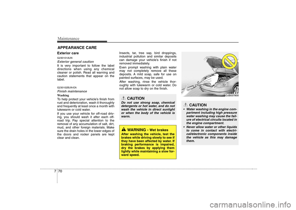
Water washing in the engine com- partment including high pressure
water washing may cause the fail- ure of electrical circuits located inthe engine compartment.
Never allow water or other liquids to come in contact with electri-cal/electronic components inside the vehicle as this may damagethem.
OJB037800
Page 319 of 340
Maintenance
76
7
EMISSION CONTROL SYSTEM
G270000AFD-EA
The emission control system of your
vehicle is covered by a written limited
warranty. Please see the warranty infor-
mation contained in the Service Passport
in your vehicle.
Your vehicle is equipped with an emis-
sion control system to meet all Australian
Design Rules (ADR) requirements. There are three emission control sys-
tems which are as follows.
(1) Crankcase emission control system
(2) Evaporative emission control system(3) Exhaust emission control system In order to assure the proper function of
the emission control systems, it is rec-
ommended that you have your car
inspected and maintained by an autho-
rised HYUNDAI dealer in accordancewith the maintenance schedule in this
manual. Caution for the Inspection and
Maintenance Test (With Electronic
Stability Program (ESP) system)
To prevent the vehicle from misfir-
ing during dynamometer testing,
turn the Electronic Stability
Program (ESP) system off by press-
ing the ESP switch.
After dynamometer testing is com- pleted, turn the ESP system back on
by pressing the ESP switch again.
G270100AUN
1. Crankcase emission control system
The positive crankcase ventilation sys-
tem is employed to prevent air pollution
caused by blow-by gases being emitted
from the crankcase. This system supplies
fresh filtered air to the crankcase through
the air intake hose. Inside the crankcase,
the fresh air mixes with blow-by gases,
which then pass through the PCV valveinto the induction system. G270200AFD-EA
2. Evaporative emission control
System
The Evaporative Emission Control
System is designed to prevent fuel
vapours from escaping into the atmos-
phere.
G270201AUN-EA
Canister
Fuel vapours generated inside the fuel tank are absorbed and stored in the
onboard canister. When the engine is
running, the fuel vapours absorbed in the
canister are drawn into the surge tank
through the purge control solenoid valve.
Page 320 of 340
777
Maintenance
G270202AUN
Purge Control Solenoid Valve (PCSV)
The purge control solenoid valve is con-
trolled by the Engine Control Module
(ECM); when the engine coolant temper-
ature is low during idling, the PCSV clos-
es so that evaporated fuel is not taken
into the engine. After the engine warms-
up during ordinary driving, the PCSV
opens to introduce evaporated fuel to the
engine.
G270300AUN
3. Exhaust emission control system
The Exhaust Emission Control System is
a highly effective system which controls
exhaust emissions while maintaining
good vehicle performance.
G270301AUN
Vehicle modifications
This vehicle should not be modified.
Modification of your vehicle could affect
its performance, safety or durability and
may even violate governmental safety
and emissions regulations.
In addition, damage or performance
problems resulting from any modification
may not be covered under warranty. G270302AUN-EA
Engine exhaust gas precautions (car-
bon monoxide)
Carbon monoxide can be present with other exhaust fumes. Therefore, if you
smell exhaust fumes of any kind inside
your vehicle, have it inspected and
repaired immediately. If you ever sus-
pect exhaust fumes are coming into
your vehicle, drive it only with all the
windows fully open. Have your vehicle
checked and repaired immediately. Do not operate the engine in confined
or closed areas (such as garages) any
more than what is necessary to move
the vehicle in or out of the area.
When the vehicle is stopped in an open area for more than a short time
with the engine running, adjust the
ventilation system (as needed) to draw
outside air into the vehicle.
Never sit in a parked or stopped vehi- cle for any extended time with the
engine running.
When the engine stalls or fails to start, excessive attempts to restart the
engine may cause damage to theemission control system.
WARNING - Exhaust
Engine exhaust gases contain car-
bon monoxide (CO). Though
colourless and odourless, it is dan-
gerous and could be lethal if
inhaled. Follow the instructions
following to avoid CO poisoning.