2009 Hyundai Santa Fe horn
[x] Cancel search: hornPage 9 of 269
F9
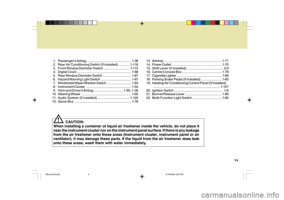
1. Passenger's
Airbag............................................... 1-36
2. Rear Air Conditioning Sw itch (If installed) ............1-116
3. Front Window Demister Switch........................... 1-115
4. Digital Clock .......................................................... 1-68
5. Rear Window Demi ster Switch .............................. 1-67
6. Hazard Warning Light Switch................................ 1-67
7. Windshield W iper/Washer Switch ..........................1-63
8. Instrument Cluster ................................................ 1-54
9. Horn and Driver' s Airbag ............................... 1-92, 1-36
10. Steering Wheel ..................................................... 1-93
11. Audio System (If installed) .................................. 1-120
12. Glove Box ............................................................. 1-78
CAUTION:
When installing a container of liquid air freshener inside the vehicle, do not place it near the instrument cluster nor on the instrument panel surface. If there is any leakagefrom the air freshener onto these areas (Instrument cluster, instrument panel or airventilator), it may damage these parts. If the liquid from the air freshener does leakonto these areas, wash them with water immediately.
! 13. Ashtray
............................................................. 1-71
14. Power Outlet ..................................................... 1-70
15. Shift Lever (If installed) ...................................... 2-9
16. Centre Console Box .......................................... 1-78
17. Cigarette Lighter ................................................ 1-69
18 Parking Brake Pedal (If installed) ...................... 1-83
19. Heating/Air Conditioning Control Panel (If installed)
....................................................................... 1-107
20. Ignition Switch ................................................... 1-6
21. Bonnet Release Lever ....................................... 1-90
22. Multi-Function Light Switch ............................... 1-60
CM-aust-00.p65 5/19/2008, 6:25 PM
9
Page 54 of 269
1
FEATURES OF YOUR HYUNDAI
43
o Do not tamper with or disconnect
SRS wiring, or other components of the SRS system. Doing so could result in injury, due to acci- dental firing of the airbags or byrendering the SRS inoperative.
o If components of the air bag sys-
tem must be discarded, or if thevehicle must be scrapped, certain safety precautions must be ob- served. Your Hyundai dealerknows these precautions and can give you the necessary informa- tion. Failure to follow these precautions and procedures could increase therisk of personal injury.
o If you sell your vehicle, make cer-
tain that this manual is trans-ferred to the new owner.
o If your car was flooded and has
soaked carpeting or water on floor-ing, you shouldn't try to start the engine; have the car towed to an authorised Hyundai dealer.
o Modification to SRS components
or wiring, including the addition of any kind of badges to the pad cover or modifications to the bodystructure, can adversely affect SRS performance and lead to possible injury.
o For cleaning the horn pad, use only a soft, dry cloth or one whichhas been moistened with plainwater. Solvents or cleaners could adversely affect the airbag cover and proper deployment of the sys-tem.
o No objects should be placed over
or near the label identifying the airbag on the steering wheel and instrument panel, because any such object could cause harm ifthe vehicle is in a crash severe enough to cause the air bag to inflate.
o If the air bag inflates, it must be replaced by an authorised Hyundaidealer. o Do not replace the bumper or the
bumper guard with the one otherthan the Hyundai genuine parts.Otherwise, it can adversely affect SRS performance and lead to un- expected injury.
CM-aust-1a.p65 5/21/2008, 2:06 PM
43
Page 103 of 269
1FEATURES OF YOUR HYUNDAI
92
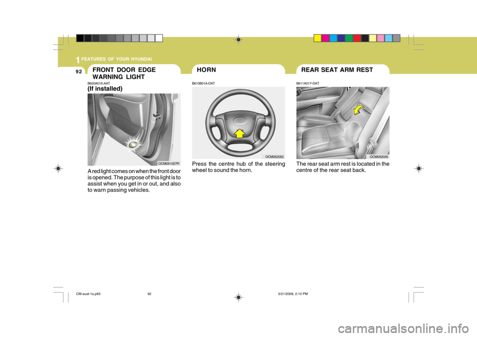
B620A01S-AAT (If installed) A red light comes on when the front door is opened. The purpose of this light is to assist when you get in or out, and alsoto warn passing vehicles.FRONT DOOR EDGE WARNING LIGHT
HORN
B610B01A-DAT Press the centre hub of the steering wheel to sound the horn.
OCM052052
REAR SEAT ARM REST
B611A01Y-DAT The rear seat arm rest is located in the centre of the rear seat back.
OCM052035
OCM051027R
CM-aust-1a.p65 5/21/2008, 2:10 PM
92
Page 212 of 269
6
DO-IT-YOURSELF MAINTENANCE
5GENERAL CHECKS
G020A03A-AAT
Engine Compartment
The following should be checked regu- larly:
o Engine oil level and condition
o Transaxle fluid level and condition
o Brake fluid level
o Engine coolant level
o Windshield washer fluid level
o Accessory drive belt condition
o Engine coolant hose condition
o Fluid leaks (on or below compo- nents)
o Power steering fluid level
o Battery condition
o Air cleaner filter condition G020B01A-DAT
Vehicle Exterior
The following should be checked
monthly:
o Overall appearance and condition
o Wheel condition and wheel nut
torque
o Exhaust system condition
o Light condition and operation
o Windshield glass condition
o Wiper blade condition
o Paint condition and body corrosion
o Fluid leaks
o Door and bonnet lock condition
o Tyre pressure and condition (including spare tyre) G020C01A-DAT Vehicle Interior The following should be checked each time when the vehicle is driven:
o Lights operation
o Windshield wiper operation
o Horn operation
o Demister, heating system operation
(and air conditioning, if installed)
o Steering operation and condition
o Mirror condition and operation
o Turn signal light operation
o Accelerator pedal operation
o Brake operation, including parking
brake
o Manual transaxle operation, includ-
ing clutch operation
o Automatic transaxle operation, in- cluding "Park" mechanism opera-tion
o Seat control condition and operation
o Seat belt condition and operation
o Sun visor operation If you notice anything that does not operate correctly or appears to befunctioning incorrectly, inspect it care- fully and seek assistance from your Hyundai dealer if service is needed.
CM-aust-6.p65 5/19/2008, 6:37 PM
5
Page 245 of 269
6DO-IT-YOURSELF MAINTENANCE
38FUSE PANEL DESCRIPTION
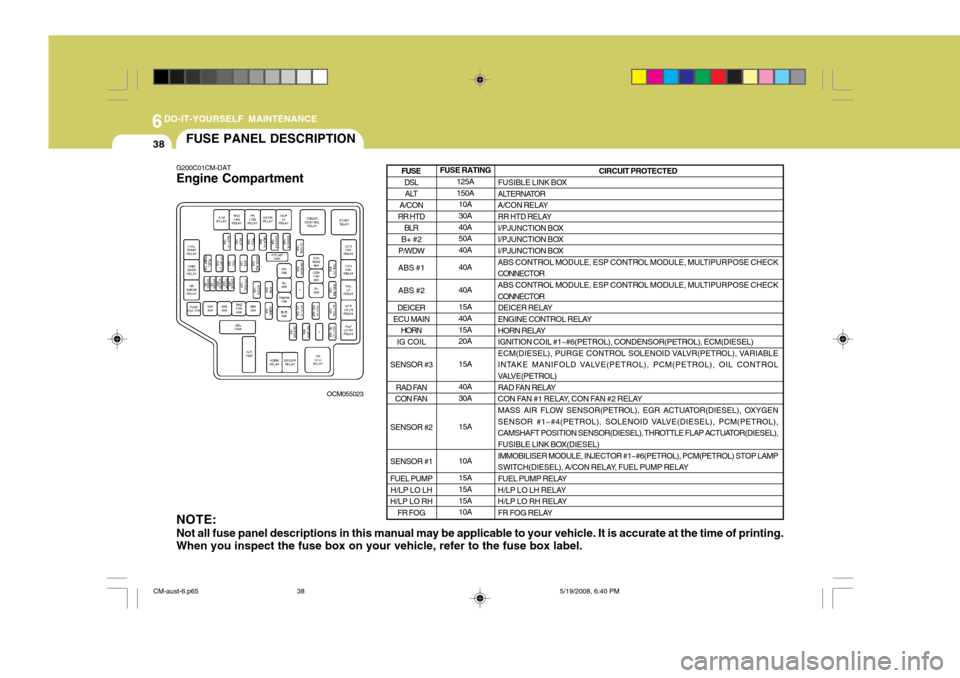
G200C01CM-DAT Engine Compartment
OCM055023
NOTE: Not all fuse panel descriptions in this manual may be applicable to your vehicle. It is accurate at the time of printing. When you inspect the fuse box on your vehicle, refer to the fuse box label.
FUSE RATING 125A 150A10A 30A 40A50A 40A 40A 40A 15A 40A 15A20A 15A40A 30A 15A 10A 15A 15A 15A10A CIRCUIT PROTECTED
FUSIBLE LINK BOX
ALTERNATOR
A/CON RELAY
RR HTD RELAY
I/PJUNCTION BOX
I/PJUNCTION BOX
I/PJUNCTION BOX
ABS CONTROL MODULE, ESP CONTROL MODULE, MULTIPURPOSE CHECK CONNECTOR
ABS CONTROL MODULE, ESP CONTROL MODULE, MULTIPURPOSE CHECK CONNECTOR
DEICER RELAY
ENGINE CONTROL RELAY
HORN RELAY IGNITION COIL #1~#6(PETROL), CONDENSOR(PETROL), ECM(DIESEL)
ECM(DIESEL), PURGE CONTROL SOLENOID VALVR(PETROL), VARIABLE
INTAKE MANIFOLD VALVE(PETROL), PCM(PETROL), OIL CONTROL
VALVE(PETROL)
RAD FAN RELAY
CON FAN #1 RELAY, CON FAN #2 RELAY
MASS AIR FLOW SENSOR(PETROL), EGR ACTUATOR(DIESEL), OXYGEN
SENSOR #1~#4(PETROL), SOLENOID VALVE(DIESEL), PCM(PETROL),
CAMSHAFT POSITION SENSOR(DIESEL), THROTTLE FLAP ACTUATOR(DIESEL),
FUSIBLE LINK BOX(DIESEL) IMMOBILISER MODULE, INJECTOR #1~#6(PETROL), PCM(PETROL) STOP LAMP
SWITCH(DIESEL), A/CON RELAY, FUEL PUMP RELAY
FUEL PUMP RELAY
H/LP LO LH RELAY
H/LP LO RH RELAY
FR FOG RELAY
DSL ALT
A/CON
RR HTD BLR
B+ #2
P/WDW ABS #1 ABS #2
DEICER
ECU MAIN HORN
IG COIL
SENSOR #3 RAD FAN
CON FAN
SENSOR #2 SENSOR #1 FUEL PUMP H/LP LO LH
H/LP LO RH
FR FOG
FUSE
CM-aust-6.p65 5/19/2008, 6:40 PM
38
Page 248 of 269
6
DO-IT-YOURSELF MAINTENANCE
41
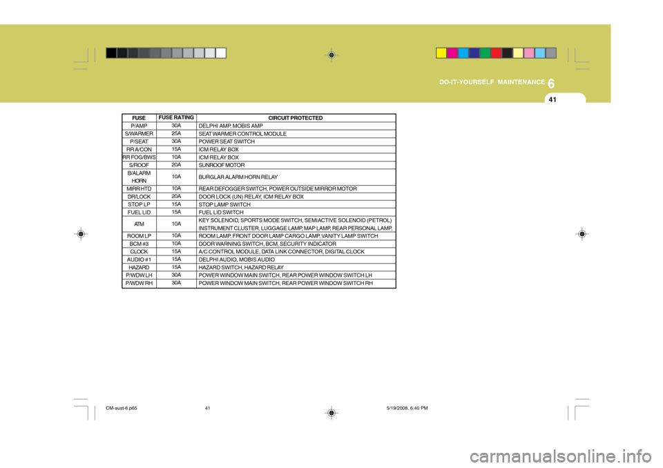
FUSE RATING 30A 25A30A 15A 10A20A 10A10A 20A 15A15A 10A10A 10A 15A15A 15A 30A30A CIRCUIT PROTECTED
DELPHI AMP, MOBIS AMP
SEAT WARMER CONTROL MODULE
POWER SEAT SWITCH
ICM RELAY BOX
ICM RELAY BOX SUNROOF MOTOR
BURGLAR ALARM HORN RELAYREAR DEFOGGER SWITCH, POWER OUTSIDE MIRROR MOTOR
DOOR LOCK (UN) RELAY, ICM RELAY BOX STOP LAMP SWITCH FUEL LID SWITCH
KEY SOLENOID, SPORTS MODE SWITCH, SEMIACTIVE SOLENOID (PETROL)
INSTRUMENT CLUSTER, LUGGAGE LAMP, MAP LAMP, REAR PERSONAL LAMP,
ROOM LAMP, FRONT DOOR LAMP CARGO LAMP, VANITY LAMP SWITCH
DOOR WARNING SWITCH, BCM, SECURITY INDICATOR
A/C CONTROL MODULE, DATA LINK CONNECTOR, DIGITAL CLOCK DELPHI AUDIO, MOBIS AUDIO
HAZARD SWITCH, HAZARD RELAYPOWER WINDOW MAIN SWITCH, REAR POWER WINDOW SWITCH LH POWER WINDOW MAIN SWITCH, REAR POWER WINDOW SWITCH RH
P/AMP
S/WARMER P/SEAT
RR A/CON
RR FOG/BWS S/ROOF
B/ALARM HORN
MIRR HTD
DR/LOCKSTOP LP
FUEL LID
AT M
ROOM LP BCM #3CLOCK
AUDIO #1
HAZARD
P/WDW LH
P/WDW RH
FUSE
CM-aust-6.p65 5/19/2008, 6:40 PM
41
Page 267 of 269
4
10INDEX
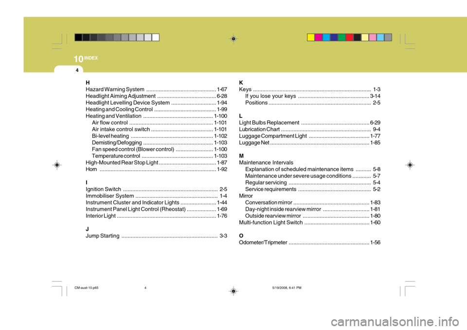
H Hazard Warning
System ............................................. 1-67
Headlight Aiming Adjustment ......................................6-28
Headlight Levelling Device System .............................1-94
Heating and Cooling Con trol ........................................ 1-99
Heating and Ventilation ............................................. 1-100
Air flow control ...................................................... 1-101
Air intake control switch ........................................ 1-101
Bi-level heating ..................................................... 1-102
Demisting/Defogging ............................................. 1-103
Fan speed control (Blower control) ........................1-100
Temperature control .............................................. 1-103
High-Mounted Rear Stop Light ..................................... 1-87
Horn ........................................................................... 1-92
IIgnition Switch ............................................................. 2-5
Immobiliser System ..................................................... 1-4
Instrument Cluster and Indicator Lights .......................1-44
Instrument Panel Light Control (Rheostat) ................... 1-69
Interior Light ................................................................ 1-76
JJump Starting .............................................................. 3-3 KKeys
............................................................................ 1-3
If you lose y our keys .............................................. 3-14
Positions .................................................................. 2-5
LLight Bulbs R eplacement............................................ 6-29
Lubrication Chart .......................................................... 9-4
Luggage Compartment Light .......................................1-77
Luggage Net ................................................................ 1-85
MMaintenance Intervals Explanation of scheduled maintenance items .......... 5-8Maintenance under severe usage conditions ............ 5-7
Regular servi cing..................................................... 5-4
Service requ irements............................................... 5-2
Mirror Conversation mirror ................................................. 1-83
Day-night inside rearview mirror .............................. 1-81
Outside rearview mirror ........................................... 1-80
Multi-function Light Switch ................... .......................1-60
OOdometer/Tripmeter .................................................... 1-56
CM-aust-10.p65 5/19/2008, 6:41 PM
4