2009 Hyundai Santa Fe fuel filter
[x] Cancel search: fuel filterPage 211 of 269
6DO-IT-YOURSELF MAINTENANCE
4
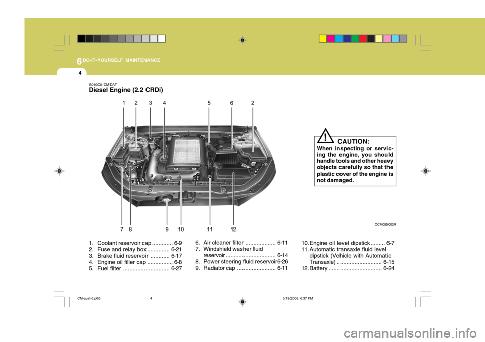
1. Coolant rese rvoir cap ............. 6-9
2. Fuse and relay box .............. 6-21
3. Brake fluid reservoir ............ 6-17
4. Engine oil filler cap ................ 6-8
5. Fuel filter ............................. 6-276. Air cleaner filter ...................
6-11
7. Windshield washer fluid
reservoir ............................... 6-14
8. Power steering fluid reservoir 6-26
9. Radiator cap ........................6-1110. Engine oil level dipstick ......... 6-7
11. Automatic transaxle fluid level
dipstick (Vehicle with AutomaticTransaxle) ............................ 6-15
12. Battery ................................. 6-24
G010C01CM-DAT
Diesel Engine (2.2 CRDi)
CAUTION:
When inspecting or servic-
ing the engine, you should handle tools and other heavy objects carefully so that theplastic cover of the engine is not damaged.
!
OCM055002R
CM-aust-6.p65 5/19/2008, 6:37 PM
4
Page 214 of 269
6
DO-IT-YOURSELF MAINTENANCE
7
NOTE:
o For good fuel economy, SAE 5W- 20 (5W-30), ILSAC GF-3 engine oil is preferred regardless of regional option and engine variation.
o If SAE 5W-20, ILSAC GF-3 engine oil is not available, secondaryrecommended engine oil for cor- responding temperature rangecan be used. G030B02CM-DAT
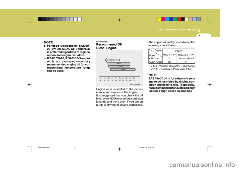
Recommened Oil Diesel Engine The engine oil quality should meet the following classification:
API Class ACEA ClassEngine
With C.P.F* 2
-
C3
Class
Without C.P.F*
2
CH4 or ABOVE B4
V.G.T* 1
* 1
V.G.T - Variable Geometry Turbocharger
* 2
C.P.F - Catalyzed Particulate Filter
OCM055020L-D
Engine oil is essential to the perfor-
mance and service of the engine.
It is suggested that you check the oil
level every 500km or before starting a long trip and more often if you are on a trip or driving in severe conditions. NOTE: SAE 0W-30 oil is for extra cold zone and to be restricted by driving con- dition and dealing area. (Especially, not recommended for sustained high loaded & high speed operation.)
CM-aust-6.p65
5/19/2008, 6:38 PM
7
Page 234 of 269
6
DO-IT-YOURSELF MAINTENANCE
27
G240A01A-DAT
POWER STEERING HOSES
It is suggested that you check the power steering hose connections for fluid leakage at those intervals speci- fied in the vehicle maintenance sched-ule in Section 5. The power steering hoses should be replaced if there is severe surface cracking, pulling, scuff-ing or worn spots. Deterioration of the hoses could cause premature failure.
HSM240-1
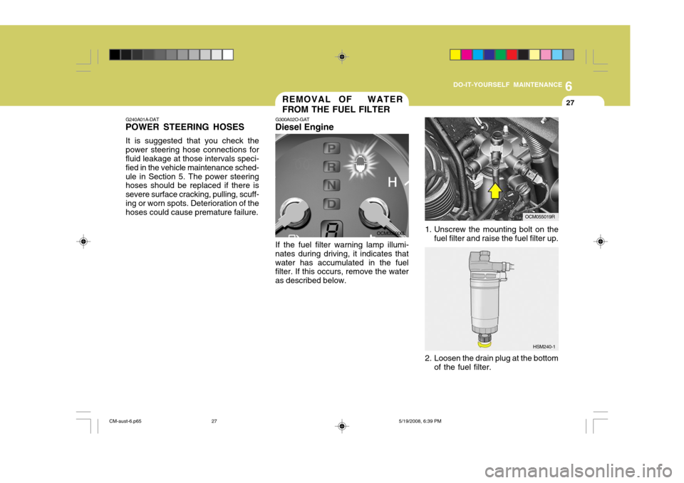
1. Unscrew the mounting bolt on the
fuel filter and raise the fuel filter up.
REMOVAL OF WATER FROM THE FUEL FILTER
G300A02O-GAT
Diesel Engine
If the fuel filter warning lamp illumi-
nates during driving, it indicates that water has accumulated in the fuel filter. If this occurs, remove the water as described below. OCM055006L
OCM055019R
2. Loosen the drain plug at the bottom of the fuel filter.
CM-aust-6.p65 5/19/2008, 6:39 PM
27
Page 235 of 269
6DO-IT-YOURSELF MAINTENANCE
28
OCM055007L
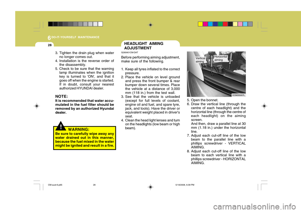
5. Open the bonnet.
6. Draw the vertical line (through the centre of each headlight) and thehorizontal line (through the centre of each headlight) on the aiming screen.And then, draw a parallel line at 30mm (1.18 in.) under the horizontalline.
7. Adjust each cut-off line of the low
beam to the parallel line with aphillips screwdriver - VERTICAL AIMING.
8. Adjust each cut-off line of the low beam to each vertical line with a phillips screwdriver - HORIZONTALAIMING.
Vertical aimingHorizontal aiming
HEADLIGHT AIMING ADJUSTMENT
G290A01CM-DAT Before performing aiming adjustment, make sure of the following.
1. Keep all tyres inflated to the correct pressure.
2. Place the vehicle on level ground and press the front bumper & rear bumper down several times. Placethe vehicle at a distance of 3,000 mm (118 in.) from the test wall.
3. See that the vehicle is unloaded (except for full levels of coolant, engine oil and fuel, and spare tyre,jack, and tools). Have the driver or equivalent weight placed in driver's seat.
4. Clean the head light lenses and turn on the headlights (low beam or highbeam).
!WARNING:
Be sure to carefully wipe away any water drained out in this manner, because the fuel mixed in the watermight be ignited and result in a fire.
3. Tighten the drain plug when water
no longer comes out.
4. Installation is the reverse order of the disassembly.
5. Check to be sure that the warning lamp illuminates when the ignitionkey is turned to 'ON', and that itgoes off when the engine is started.If in doubt, consult your nearestauthorized HYUNDAI dealer.
NOTE: It is recommended that water accu- mulated in the fuel filter should be removed by an authorized Hyundai dealer.
CM-aust-6.p65 5/19/2008, 6:39 PM
28
Page 246 of 269
6
DO-IT-YOURSELF MAINTENANCE
39
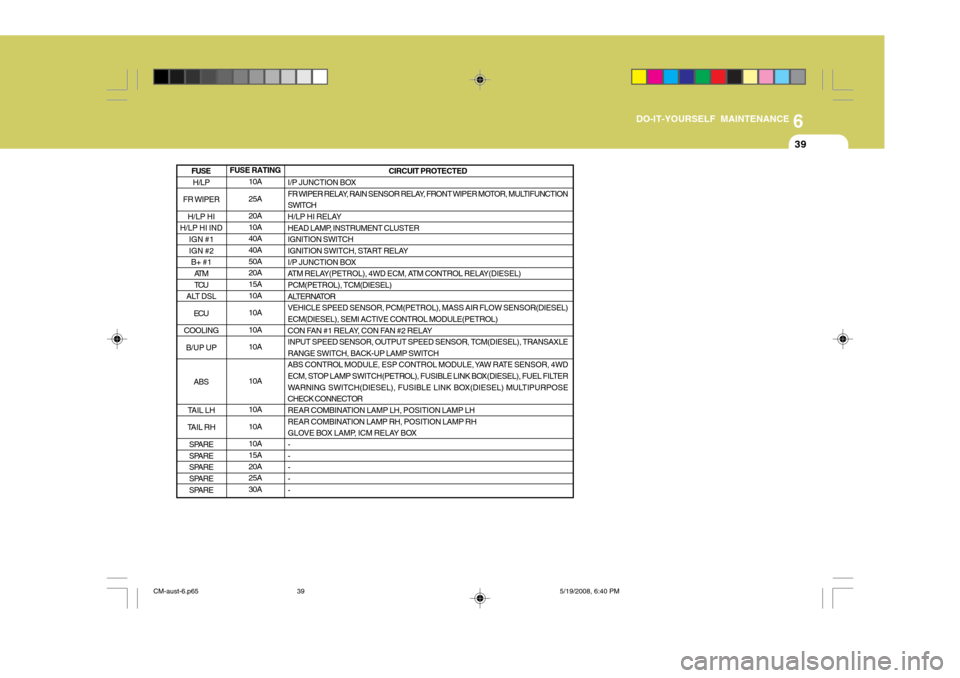
FUSE RATING 10A 25A20A 10A40A 40A 50A20A 15A 10A 10A10A10A 10A 10A 10A10A 15A 20A25A 30A CIRCUIT PROTECTED
I/P JUNCTION BOX
FR WIPER RELAY, RAIN SENSOR RELAY, FRONT WIPER MOTOR, MULTIFUNCTION
SWITCH
H/LP HI RELAY
HEAD LAMP, INSTRUMENT CLUSTER IGNITION SWITCH
IGNITION SWITCH, START RELAY
I/P JUNCTION BOX
ATM RELAY(PETROL), 4WD ECM, ATM CONTROL RELAY(DIESEL)PCM(PETROL), TCM(DIESEL)
ALTERNATOR VEHICLE SPEED SENSOR, PCM(PETROL), MASS AIR FLOW SENSOR(DIESEL)ECM(DIESEL), SEMI ACTIVE CONTROL MODULE(PETROL)
CON FAN #1 RELAY, CON FAN #2 RELAY INPUT SPEED SENSOR, OUTPUT SPEED SENSOR, TCM(DIESEL), TRANSAXLERANGE SWITCH, BACK-UP LAMP SWITCH
ABS CONTROL MODULE, ESP CONTROL MODULE, YAW RATE SENSOR, 4WD
ECM, STOP LAMP SWITCH(PETROL), FUSIBLE LINK BOX(DIESEL), FUEL FILTER
WARNING SWITCH(DIESEL), FUSIBLE LINK BOX(DIESEL) MULTIPURPOSECHECK CONNECTOR
REAR COMBINATION LAMP LH, POSITION LAMP LH
REAR COMBINATION LAMP RH, POSITION LAMP RH
GLOVE BOX LAMP, ICM RELAY BOX - -- - -
H/LP
FR WIPER H/LP HI
H/LP HI IND IGN #1 IGN #2B+ #1
AT MTCU
ALT DSL
ECU
COOLING B/UP UP
ABS
TAIL LH
TAIL RH SPARE
SPARE
SPARE
SPARE
SPARE
FUSE
CM-aust-6.p65 5/19/2008, 6:40 PM
39
Page 250 of 269
7EMISSION CONTROL SYSTEMS
2EMISSION CONTROL SYSTEM
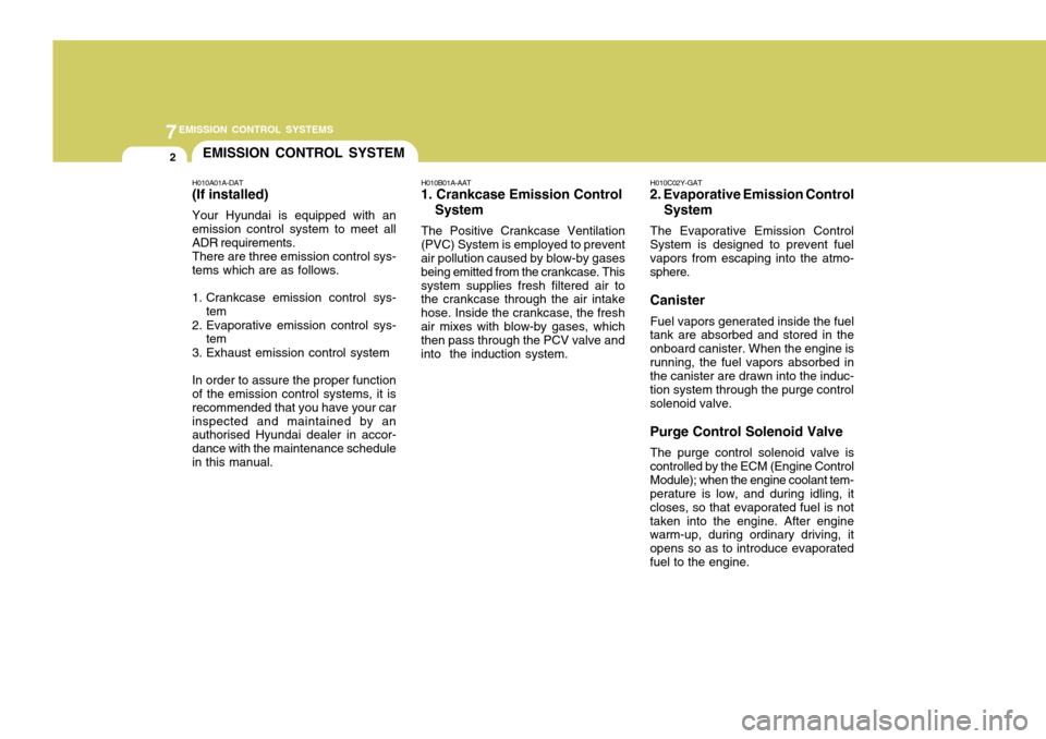
H010A01A-DAT (If installed) Your Hyundai is equipped with an emission control system to meet all ADR requirements. There are three emission control sys- tems which are as follows.
1. Crankcase emission control sys- tem
2. Evaporative emission control sys- tem
3. Exhaust emission control systemIn order to assure the proper function of the emission control systems, it is recommended that you have your carinspected and maintained by an authorised Hyundai dealer in accor- dance with the maintenance schedulein this manual. H010B01A-AAT
1. Crankcase Emission Control
System
The Positive Crankcase Ventilation
(PVC) System is employed to prevent air pollution caused by blow-by gases being emitted from the crankcase. Thissystem supplies fresh filtered air to the crankcase through the air intake hose. Inside the crankcase, the freshair mixes with blow-by gases, which then pass through the PCV valve and into the induction system. H010C02Y-GAT
2. Evaporative Emission Control
System
The Evaporative Emission Control
System is designed to prevent fuel vapors from escaping into the atmo- sphere. Canister
Fuel vapors generated inside the fuel
tank are absorbed and stored in the onboard canister. When the engine isrunning, the fuel vapors absorbed in the canister are drawn into the induc- tion system through the purge controlsolenoid valve. Purge Control Solenoid Valve
The purge control solenoid valve is
controlled by the ECM (Engine Control Module); when the engine coolant tem- perature is low, and during idling, it closes, so that evaporated fuel is nottaken into the engine. After engine warm-up, during ordinary driving, it opens so as to introduce evaporatedfuel to the engine.
Page 266 of 269
3
10
INDEX
D Demisting/Defogging
................................................. 1-105
Door Central door locks .................................................... 1-9
Door locks ................................................................ 1-6
Front door edge warning light ..................................1-92
Locking, unlocking front doors with a key ................. 1-7
Drink Holder ................................................................ 1-71
Driving Driving for economy ................................................ 2-21
Smooth cornering .................................................... 2-22
Winter driving .......................................................... 2-23
EEmission Control System ............................................ 7-2
Engine Before starting the engine ........................................ 2-3Compartment ........................................................... 6-2
Coolant .................................................................... 6-9
Coolant temperature gauge .....................................1-54
If the engine overheats ............................................. 3-4
Number .................................................................... 8-2
Oil ............................................................................ 6-6Starting .................................................................... 2-6
Engine Exhaust Can Be Dangerous ............................. 2-2FFan Speed
Control .................................................... 1-100
Fog Light Front ....................................................................... 1-66
Rear ........................................................................ 1-67
Front Seats Adjustable front seats ............................................. 1-15
Adjustable headrests .............................................. 1-16
Adjusting seat forward and rearward ........................ 1-15
Adjusting seatback angle .. ......................................1-15
Fuel Capacity .................................................................. 9-2
Gauge ..................................................................... 1-54
Recommendations ................................................... 1-2
Fuel Filler Lid Remote release ....................................................... 1-88
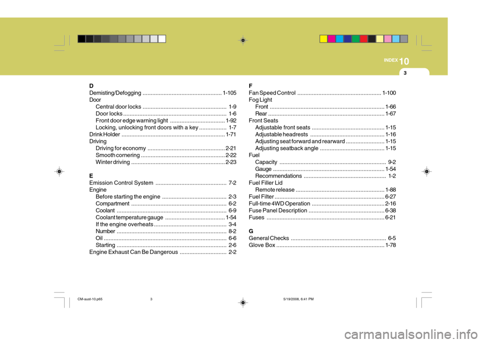
Fuel Filter .................................................................... 6-27
Full-time 4 WD Operation ............................................. 2-16
Fuse Panel Description ............................................... 6-38
Fuses ......................................................................... 6-21
GGeneral Checks ........................................................... 6-5
Glove Box ................................................................... 1-78
CM-aust-10.p65 5/19/2008, 6:41 PM
3