Page 8 of 303

Your vehicle at a glance
2
2
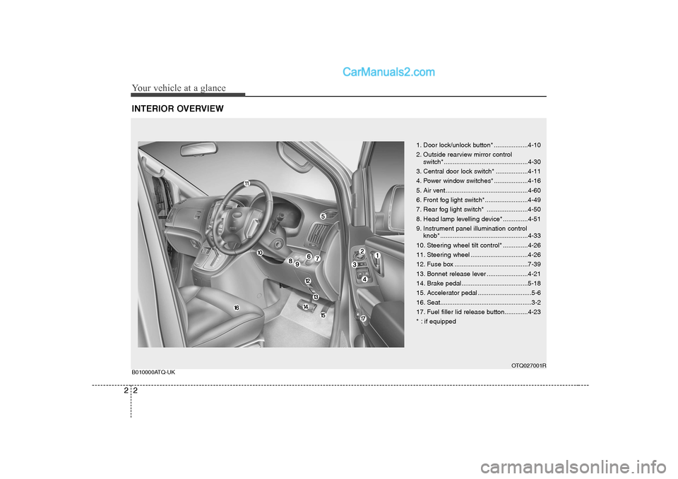
INTERIOR OVERVIEW
1. Door lock/unlock button* ...................4-10
2. Outside rearview mirror control
switch*...............................................4-30
3. Central door lock switch* ..................4-11
4. Power window switches* ...................4-16
5. Air vent ..............................................4-60
6. Front fog light switch*........................4-49
7. Rear fog light switch* .......................4-50
8. Head lamp levelling device* ..............4-51
9. Instrument panel illumination control knob* .................................................4-33
10. Steering wheel tilt control* ..............4-26
11. Steering wheel ................................4-26
12. Fuse box .........................................7-39
13. Bonnet release lever .......................4-21
14. Brake pedal .....................................5-18
15. Accelerator pedal ..............................5-6
16. Seat...................................................3-2
17. Fuel filler lid release button.............4-23
* : if equipped
OTQ027001R
B010000ATQ-UK
Page 10 of 303
Your vehicle at a glance
4
2
ENGINE COMPARTMENT
1. Power steering fluid reservoir ...........7-17
2. Automatic transmission fluid
dipstick*.............................................7-18
3. Engine oil filler cap ...........................7-12
4. Brake fluid reservoir ..........................7-16
5. Fuse box ...........................................7-39
6. Negative battery terminal..................7-27
7. Positive battery terminal ...................7-27
8. Engine coolant reservoir ...................7-13
9. Engine oil dipstick .............................7-12
10. Radiator cap ...................................7-15
11. Windscreen washer fluid reservoir..7-20
12. Air cleaner.......................................7-22
* : if equipped
OTQ027003R
B030000ATQ-UK* The actual engine room in the vehicle may differ from the illustration.
Page 51 of 303

341
Safety features of your vehicle
C040400BTQ-UK
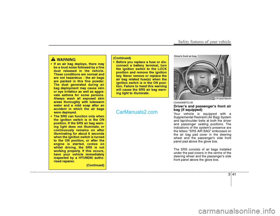
Driver's and passenger's front air
bag (if equipped)
Your vehicle is equipped with a
Supplemental Restraint (Air Bag) System
and lap/shoulder belts at both the driver
and passenger seating positions. Theindications of the system's presence are
the letters "SRS AIR BAG" embossed on
the air bag pad cover in the steeringwheel and the passenger's side front
panel pad above the glove box. The SRS consists of air bags installed
under the pad covers in the centre of the
steering wheel and the passenger's side
front panel above the glove box.
WARNING
If an air bag deploys, there may be a loud noise followed by a fine
dust released in the vehicle.These conditions are normal and
are not hazardous - the air bags
are packed in this fine powder.
The dust generated during air
bag deployment may cause skin
or eye irritation as well as aggra-
vate asthma for some persons.
Always wash all exposed skin
areas thoroughly with lukewarmwater and a mild soap after an
accident in which the air bags
were deployed.
The SRS can function only when the ignition switch is in the ON
position. If the SRS air bag warn-
ing light does not illuminate, or
continuously remains on after
illuminating for about 6 seconds
when the ignition switch is turned
to the ON position, or after the
engine is started, comes on
whilst driving, the SRS is not
working properly. If this occurs,
have your vehicle immediately
inspected by a HYUNDAI autho-
rised repairer.
(Continued)(Continued)
Before you replace a fuse or dis-connect a battery terminal, turn
the ignition switch to the LOCK
position and remove the ignition
key. Never remove or replace the
air bag related fuse(s) when the
ignition switch is in the ON posi-
tion. Failure to heed this warning
will cause the SRS air bag warn-
ing light to illuminate.
OTQ037024/H
Driver’s front air bag
Page 221 of 303
Maintenance
2
7
ENGINE COMPARTMENT
OTQ027003R
1. Power steering fluid reservoir
2. Automatic transmission fluid dipstick
(if equipped)
3. Engine oil filler cap
4. Fuel filter
5. Brake fluid reservoir
6. Fuse box
7. Negative battery terminal
8. Positive battery terminal
9. Engine coolant reservoir
10. Engine oil dipstick
11. Radiator cap
12. Windscreen washer fluid reservoir
13. Air cleaner
* The actual engine room in the vehicle may differ from the illustration.
■
■
Diesel Engine
Page 222 of 303
73
Maintenance
OTQ077066R
1. Power steering fluid reservoir
2. Automatic transmission fluid dipstick
(if equipped)
3. Engine oil filler cap
4. Brake fluid reservoir
5. Fuse box
6. Negative battery terminal
7. Positive battery terminal
8. Engine coolant reservoir
9. Engine oil dipstick
10. Radiator cap
11. Windscreen washer fluid reservoir
12. Air cleaner
■
■
Petrol Engine
* The actual engine room in the vehicle may differ from the illustration.
Page 265 of 303

Maintenance
46
7
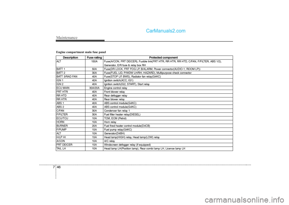
Engine compartment main fuse panel
Description Fuse rating Protected component
ALT 150A Fuse(A/CON, FRT DEICER), Fusible link(FRT HTR, RR HTR, RR HTD, C/FAN, F/FILTER, ABS 1/2), Generator, E/R fuse & relay box RH
BATT 1 50A Fuse(DR LOCK, FRT FOG LP, B/ALARM, Power connector(AUDIO-1, ROOM LP))
BATT 2 30A Fuse(FUEL LID, P/WDW LH/RH, HAZARD), Multipurpose check connector
BATT 3/RAD FAN 40A Fuse(STOP LP, BWS), Radiator fan relay(G4KC)
IGN 1 40A Ignition switch(ACC, IG1)
IGN 2 40A Ignition switch(IG2, START), Start relay
ECU MAIN 30A/20A Engine control relay
FRT HTR 40A Front blower relay
RR HTD 40A Rear defogger relay
RR HTR 40A Rear blower relay
ABS 1 40A ABS control module(G4KC)
ABS 2 40A ABS control module(G4KC)
C/FAN 30A Condenser fan relay 1
F/FILTER 30A Fuel filter heater relay(DIESEL)
ECU/TCU 10A TCM, ECM (Petrol)
HORN 10A Horn relay
BURNER 20A Fuel fired heater control module(D4CB)
F/PUMP 15A Fuel pump relay(G4KC)
ALT 10A Generator(D4BH)
H/LP HI 15A Head lamp(HIGH) relay, Head lamp(LOW) relay
A/CON 10A A/C relay
FRT DEICER 15A Windscreen defogger relay (if equipped)
TAIL LH 10A Head lamp LH(Position lamp), Rear combi lamp LH, License lamp LH