Page 248 of 303
729
Maintenance
G190200AUN-UK
Battery recharging
Your vehicle has a maintenance-free,
calcium-based battery.
If the battery becomes discharged in ashort time (because, for example, the
headlights or interior lights were left on
whilst the vehicle was not in use),
recharge it by slow charging (trickle)
for 10 hours.
If the battery gradually discharges because of high electric load whilst the
vehicle is being used, recharge it at 20-
30A for two hours.
G190300ATQ Reset items
Items should be reset after the battery
has been discharged or the battery hasbeen disconnected.
Climate control system (See section 4)
Clock (See section 4)
Audio (See section 4)(Continued)
Disconnect the battery charger in the following order.
1. Turn off the battery charger main switch.
2. Unhook the negative clamp from the negative battery terminal.
3. Unhook the positive clamp from the positive battery terminal.
Before performing maintenance or recharging the battery, turn off all accessories and stop the
engine.
The negative battery cable must be removed first and installed
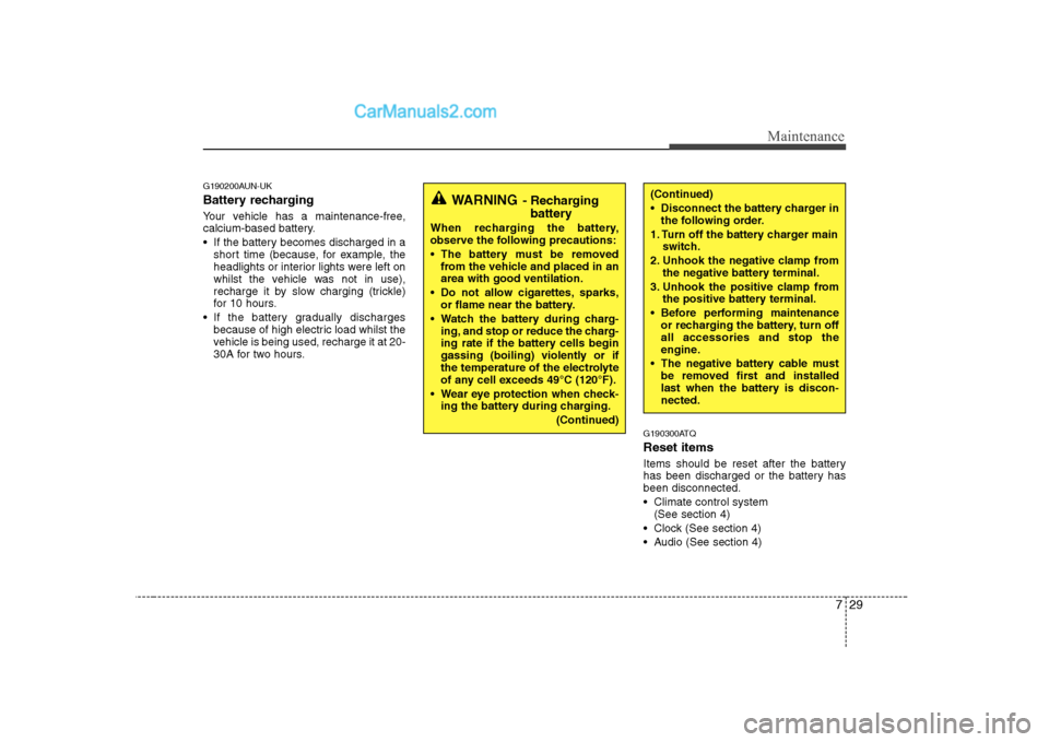
last when the battery is discon-nected.WARNING - Recharging
battery
When recharging the battery,
observe the following precautions:
The battery must be removed from the vehicle and placed in an area with good ventilation.
Do not allow cigarettes, sparks, or flame near the battery.
Watch the battery during charg- ing, and stop or reduce the charg-
ing rate if the battery cells begin
gassing (boiling) violently or if
the temperature of the electrolyte
of any cell exceeds 49°C (120°F).
Wear eye protection when check- ing the battery during charging.
(Continued)
Page 258 of 303
739
Maintenance
FUSES
G210000AEN-UK
A vehicle’s electrical system is protected
from electrical overload damage by
fuses. This vehicle has 3 fuse panels, one locat-
ed in the driver’s side panel bolster, the
other in the engine compartment.
If any of your vehicle’s lights, acces-
sories, or controls do not work, check the
appropriate circuit fuse. If a fuse has
blown, the element inside the fuse will bemelted.
If the electrical system does not work,
first check the driver’s side fuse panel.
Always replace a blown fuse with one of
the same rating.
If the replacement fuse blows, this indi-
cates an electrical problem. Avoid using
the system involved and immediately
consult a HYUNDAI authorised repairer.
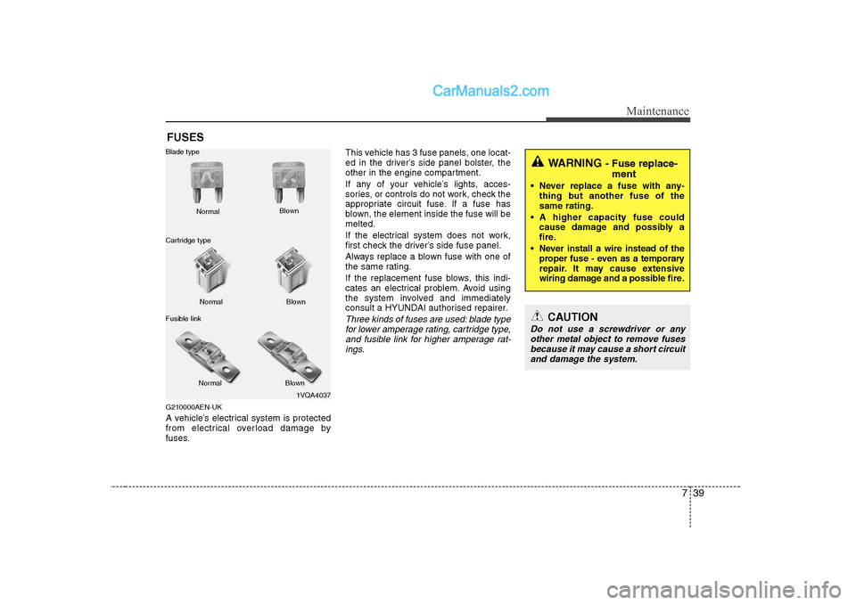
Three kinds of fuses are used: blade type
for lower amperage rating, cartridge type,
and fusible link for higher amperage rat-ings.
1VQA4037
Normal
Normal
Blade type
Cartridge type
Fusible link Blown
Blown
Normal Blown
WARNING - Fuse replace-
ment
Never replace a fuse with any- thing but another fuse of the same rating.
A higher capacity fuse could cause damage and possibly a
fire.
Never install a wire instead of the proper fuse - even as a temporary
repair. It may cause extensive
wiring damage and a possible fire.
CAUTION
Do not use a screwdriver or any
other metal object to remove fusesbecause it may cause a short circuit and damage the system.
Page 259 of 303
Maintenance
40
7
G210100AFD-UK Instrument panel fuse replace- ment
1. Turn the ignition switch and all other
switches off.
2. Open the fuse panel cover. 3. Pull the suspected fuse straight out.
Use the removal tool provided in the
engine compartment fuse panel.
4. Check the removed fuse; replace it if it is blown.
Spare fuses are provided in the inner
fuse panel (or in the engine compart- ment fuse panel).
5. Push in a new fuse of the same rating, and make sure it fits tightly in the clips.
If it fits loosely, consult a HYUNDAI
authorised repairer.
If you do not have a spare, use a fuse of the same rating from a circuit you may not need for operating the vehicle, suchas the cigarette lighter fuse.
If the headlights or other electrical com-
ponents do not work and the fuses are
OK, check the fuse panel in the engine
compartment. If a fuse is blown, it mustbe replaced.
OTQ077041ROTQ077040R
Page 261 of 303
Maintenance
42
7
3. Check the removed fuse; replace it if it
is blown. To remove or insert the fuse, use the fuse puller in the engine com-
partment fuse panel.
4. Push in a new fuse of the same rating, and make sure it fits tightly in the clips.
If it fits loosely, consult a HYUNDAI
authorised repairer.
G210201AEN-UK
Main fuse
If the main fuse is blown, it must be
removed as follows:
1. Disconnect the negative battery cable.
2. Remove the nuts shown in the pictureabove.
3. Replace the fuse with a new one of the same rating.
4. Reinstall in the reverse order of removal.
✽✽ NOTICE
If the main fuse is blown, consult a
HYUNDAI authorised repairer.
CAUTION
After checking the fuse panel in the engine compartment, securelyinstall the fuse panel cover. If not,electrical failures may occur fromwater contact.OTQ077045
Page 265 of 303
Maintenance
46
7
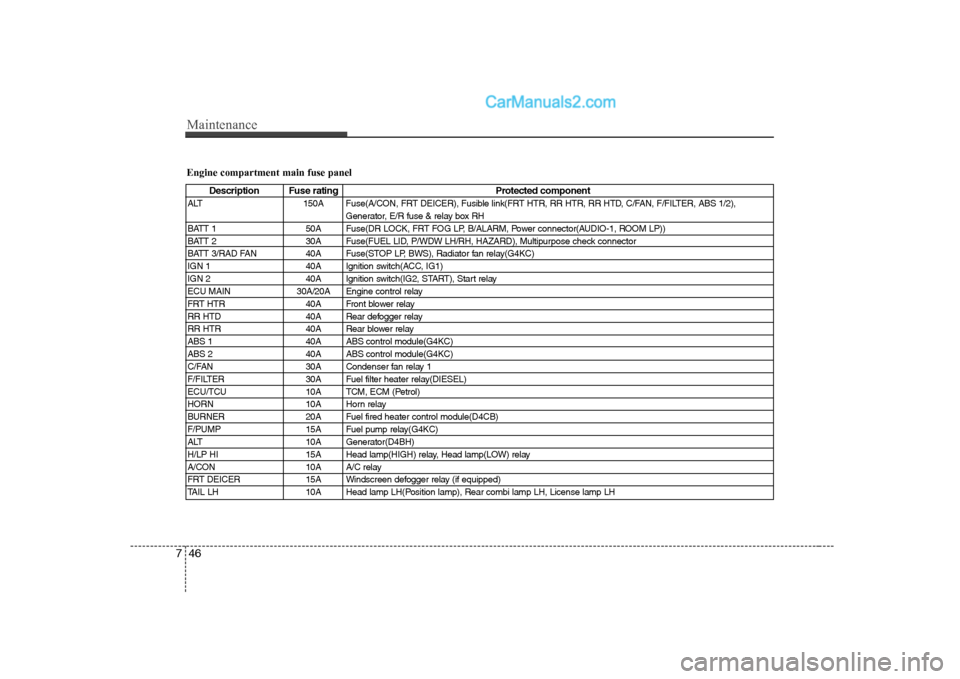
Engine compartment main fuse panel
Description Fuse rating Protected component
ALT 150A Fuse(A/CON, FRT DEICER), Fusible link(FRT HTR, RR HTR, RR HTD, C/FAN, F/FILTER, ABS 1/2), Generator, E/R fuse & relay box RH
BATT 1 50A Fuse(DR LOCK, FRT FOG LP, B/ALARM, Power connector(AUDIO-1, ROOM LP))
BATT 2 30A Fuse(FUEL LID, P/WDW LH/RH, HAZARD), Multipurpose check connector
BATT 3/RAD FAN 40A Fuse(STOP LP, BWS), Radiator fan relay(G4KC)
IGN 1 40A Ignition switch(ACC, IG1)
IGN 2 40A Ignition switch(IG2, START), Start relay
ECU MAIN 30A/20A Engine control relay
FRT HTR 40A Front blower relay
RR HTD 40A Rear defogger relay
RR HTR 40A Rear blower relay
ABS 1 40A ABS control module(G4KC)
ABS 2 40A ABS control module(G4KC)
C/FAN 30A Condenser fan relay 1
F/FILTER 30A Fuel filter heater relay(DIESEL)
ECU/TCU 10A TCM, ECM (Petrol)
HORN 10A Horn relay
BURNER 20A Fuel fired heater control module(D4CB)
F/PUMP 15A Fuel pump relay(G4KC)
ALT 10A Generator(D4BH)
H/LP HI 15A Head lamp(HIGH) relay, Head lamp(LOW) relay
A/CON 10A A/C relay
FRT DEICER 15A Windscreen defogger relay (if equipped)
TAIL LH 10A Head lamp LH(Position lamp), Rear combi lamp LH, License lamp LH
Page 282 of 303
763
Maintenance
G270201AUN-UK
Canister
Fuel vapours generated inside the fuel tank are absorbed and stored in the
onboard canister. When the engine is
running, the fuel vapours absorbed in the
canister are drawn into the surge tank
through the purge control solenoid valve.
G270202AUN
Purge Control Solenoid Valve (PCSV)
The purge control solenoid valve is con-
trolled by the Engine Control Module
(ECM); when the engine coolant temper-
ature is low during idling, the PCSV clos-
es so that evaporated fuel is not taken
into the engine. After the engine warms-
up during ordinary driving, the PCSV
opens to introduce evaporated fuel to the
engine.G270300AUN-UK
3. Exhaust emission control
system
The Exhaust Emission Control System is
a highly effective system which controls
exhaust emissions whilst maintaining
good vehicle performance.
G270301AUN
Vehicle modifications
This vehicle should not be modified.
Modification of your vehicle could affect
its performance, safety or durability and
may even violate governmental safety
and emissions regulations.
In addition, damage or performance
problems resulting from any modification
may not be covered under warranty. G270302AUN-UK
Engine exhaust gas precautions (car-
bon monoxide)
Carbon monoxide can be present with other exhaust fumes. Therefore, if you
smell exhaust fumes of any kind inside
your vehicle, have it inspected and
repaired immediately. If you ever sus-
pect exhaust fumes are coming into
your vehicle, drive it only with all the
windows fully open. Have your vehicle
checked and repaired immediately.
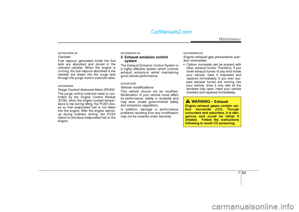
WARNING - Exhaust
Engine exhaust gases contain car-
bon monoxide (CO). Though
colourless and odourless, it is dan-
gerous and could be lethal if
inhaled. Follow the instructions
following to avoid CO poisoning.
Page 292 of 303
Specifications
6
9
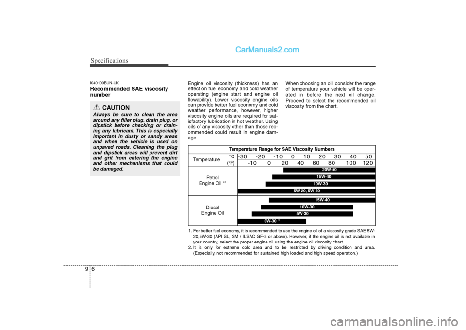
I040100BUN-UK Recommended SAE viscosity
number Engine oil viscosity (thickness) has an
effect on fuel economy and cold weather
operating (engine start and engine oil
flowability). Lower viscosity engine oils
can provide better fuel economy and cold
weather performance, however, higher
viscosity engine oils are required for sat-
isfactory lubrication in hot weather. Using
oils of any viscosity other than those rec-ommended could result in engine dam-
age.When choosing an oil, consider the range
of temperature your vehicle will be oper-
ated in before the next oil change.Proceed to select the recommended oil
viscosity from the chart.
CAUTION
Always be sure to clean the area
around any filler plug, drain plug, or dipstick before checking or drain- ing any lubricant. This is especially
important in dusty or sandy areasand when the vehicle is used on unpaved roads. Cleaning the plugand dipstick areas will prevent dirt
and grit from entering the engineand other mechanisms that could be damaged.
Temperature Range for SAE Viscosity Numbers
Temperature
Petrol
Engine Oil *
1
°C
(°F)-30 -20 -10 0 10 20 30 40 50 -10 0 20 40 60 80 100 120
Diesel
Engine Oil
5W-30
15W-40
10W-30
0W-30 *2
1. For better fuel economy, it is recommended to use the engine oil of a viscosity grade SAE 5W-
20,5W-30 (API SL, SM / ILSAC GF-3 or above). However, if the engine oil is not available in
your country, select the proper engine oil using the engine oil viscosity chart.
2. It is only for extreme cold area and to be restricted by driving condition and area. (Especially, not recommended for sustained high loaded and high speed operation.)
20W-50
10W-30
15W-40
5W-20, 5W-30