2009 Hyundai Getz engine
[x] Cancel search: enginePage 160 of 191
6- 18 DO-IT-YOURSELF MAINTENANCE
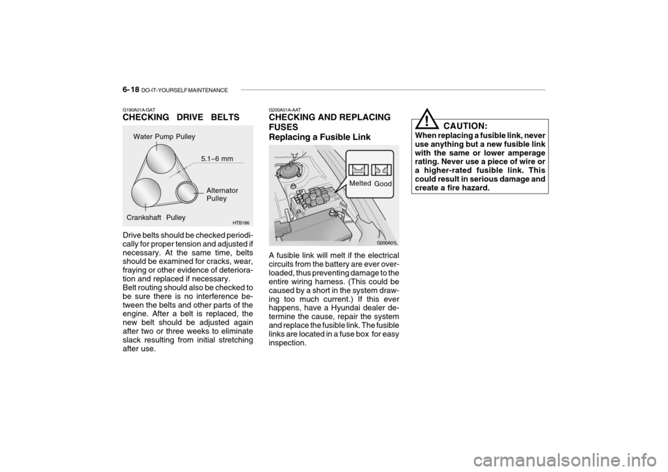
A fusible link will melt if the electrical circuits from the battery are ever over-loaded, thus preventing damage to the entire wiring harness. (This could be caused by a short in the system draw-ing too much current.) If this ever happens, have a Hyundai dealer de- termine the cause, repair the systemand replace the fusible link. The fusible links are located in a fuse box for easy inspection. CAUTION:
When replacing a fusible link, neveruse anything but a new fusible linkwith the same or lower amperage rating. Never use a piece of wire or a higher-rated fusible link. Thiscould result in serious damage and create a fire hazard.
!
G200A01A-AAT CHECKING AND REPLACING FUSESReplacing a Fusible Link
G200A01L
Melted
Good
Water Pump Pulley
Alternator Pulley
Crankshaft Pulley 5.1~6 mm
G190A01A-GAT CHECKING DRIVE BELTS Drive belts should be checked periodi- cally for proper tension and adjusted ifnecessary. At the same time, belts should be examined for cracks, wear, fraying or other evidence of deteriora-tion and replaced if necessary. Belt routing should also be checked to be sure there is no interference be-tween the belts and other parts of the engine. After a belt is replaced, the new belt should be adjusted againafter two or three weeks to eliminate slack resulting from initial stretching after use. HTB186
Page 163 of 191
DO-IT-YOURSELF MAINTENANCE 6- 21
If any electrolyte gets into your eyes, flush your eyeswith clean water for at least 15 minutes and get immedi- ate medical attention. If pos-sible, continue to apply water with a sponge or cloth until medical attention is re-ceived. If electrolyte gets on your skin, thoroughly wash thecontacted area. If you feel a pain or a burn- ing sensation, get medicalattention immediately. Wear eye protection when charging or working near abattery. Always provide ventilation when working in an en-closed space.
o When lifting a plastic-cased bat- tery, excessive pressure on the case may cause battery acid to leak, resulting in personal injury.Lift with a battery carrier or with your hands on opposite corners.
!
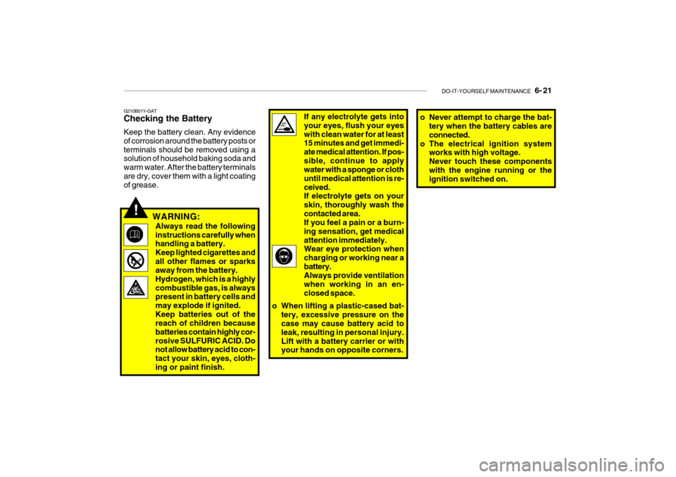
G210B01Y-GAT Checking the Battery Keep the battery clean. Any evidence of corrosion around the battery posts orterminals should be removed using a solution of household baking soda and warm water. After the battery terminalsare dry, cover them with a light coating of grease.
WARNING:
Always read the following instructions carefully when handling a battery. Keep lighted cigarettes andall other flames or sparks away from the battery. Hydrogen, which is a highlycombustible gas, is always present in battery cells and may explode if ignited.Keep batteries out of the reach of children because batteries contain highly cor-rosive SULFURIC ACID. Do not allow battery acid to con- tact your skin, eyes, cloth-ing or paint finish. o Never attempt to charge the bat-
tery when the battery cables areconnected.
o The electrical ignition system works with high voltage.Never touch these componentswith the engine running or the ignition switched on.
Page 164 of 191
6- 22 DO-IT-YOURSELF MAINTENANCE
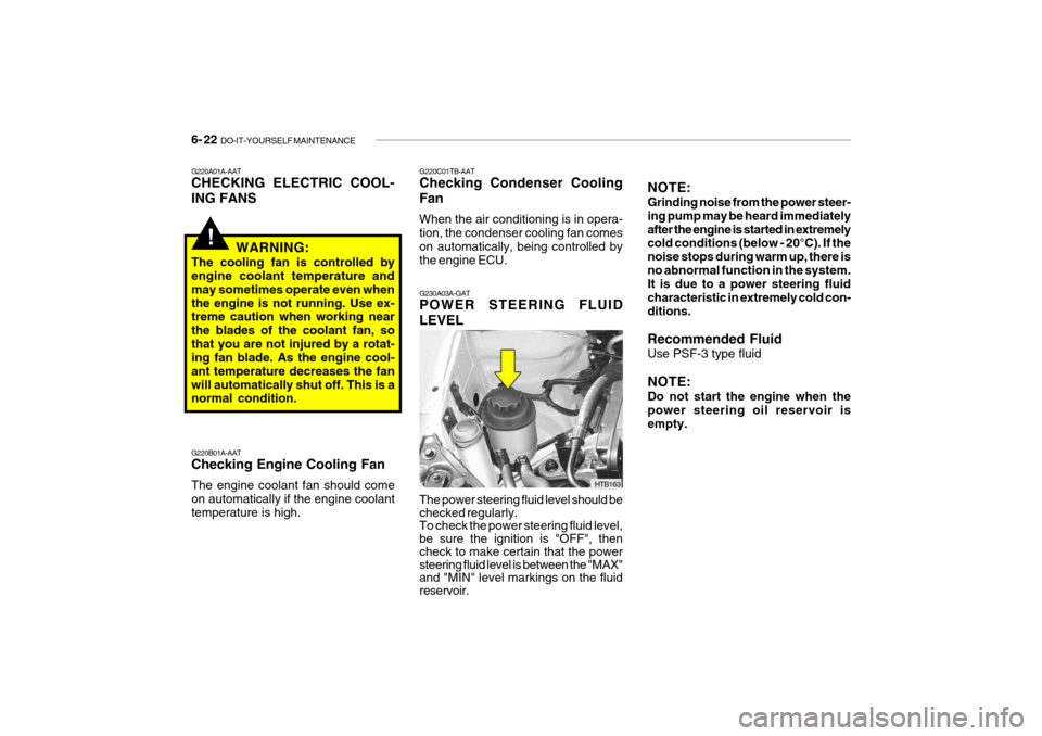
G230A03A-GAT POWER STEERING FLUID LEVEL The power steering fluid level should be checked regularly. To check the power steering fluid level, be sure the ignition is "OFF", then check to make certain that the power steering fluid level is between the "MAX" and "MIN" level markings on the fluid reservoir. HTB163NOTE: Grinding noise from the power steer- ing pump may be heard immediatelyafter the engine is started in extremely cold conditions (below - 20°C). If the noise stops during warm up, there isno abnormal function in the system. It is due to a power steering fluid characteristic in extremely cold con-ditions. Recommended Fluid Use PSF-3 type fluid NOTE: Do not start the engine when the power steering oil reservoir is empty.
!
G220A01A-AAT CHECKING ELECTRIC COOL- ING FANS
WARNING:
The cooling fan is controlled by engine coolant temperature and may sometimes operate even whenthe engine is not running. Use ex- treme caution when working near the blades of the coolant fan, sothat you are not injured by a rotat- ing fan blade. As the engine cool- ant temperature decreases the fanwill automatically shut off. This is a normal condition. G220B01A-AAT Checking Engine Cooling Fan The engine coolant fan should come on automatically if the engine coolanttemperature is high. G220C01TB-AAT Checking Condenser Cooling Fan When the air conditioning is in opera- tion, the condenser cooling fan comes on automatically, being controlled by
the engine ECU.
Page 165 of 191
DO-IT-YOURSELF MAINTENANCE 6- 23
G290A01FC-DAT HEADLIGHT AIMING ADJUSTMENT Before performing aiming adjustment, make sure of the following.
1. Keep all tyres inflated to the correct
pressure.
2. Place the vehicle on level ground
and press the front bumper & rear bumper down several times. Place the vehicle at a distance of 3,000 mm (118 in.) from the test wall.
3. See that the vehicle is unloaded (except for full levels of coolant,engine oil and fuel, and spare tyre,jack, and tools).
4. Clean the head light lenses and turn
on the headlights (low beam).
G240A01A-DAT POWER STEERING HOSES It is suggested that you check the power steering hose connections forfluid leakage at those intervals speci- fied in the vehicle maintenance schedule in Section 5. The power steer-ing hoses should be replaced if there is severe surface cracking, pulling, scuff- ing or worn spots. Deterioration of thehoses could cause premature failure.
HTB269
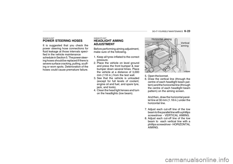
Horizontal aiming
Vertical
aiming
5. Open the bonnet.
6. Draw the vertical line (through the centre of each headlight beam pat-tern) and the horizontal line (throughthe centre of each headlight beam pattern) on the aiming screen. And then, draw the horizontal paral- lel line at 30 mm (1.18 in.) under the horizontal line.
7. Adjust each cut-off line of the low beam to the parallel line with a phillipsscrewdriver - VERTICAL AIMING.
8. Adjust each cut-off line of the low
beam to each vertical line with aphillips screwdriver - HORIZONTAL AIMING.
Page 172 of 191
6- 30 DO-IT-YOURSELF MAINTENANCE
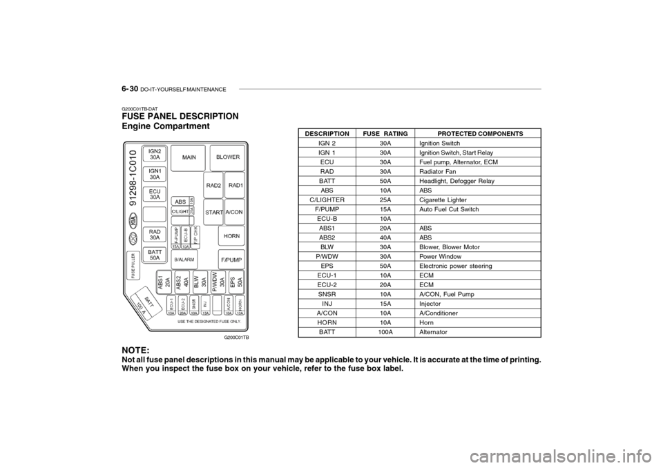
G200C01TB-DAT FUSE PANEL DESCRIPTION Engine Compartment
G200C01TB PROTECTED COMPONENTS
Ignition Switch
Ignition Switch, Start Relay
Fuel pump, Alternator, ECM
Radiator FanHeadlight, Defogger RelayABSCigarette LighterAuto Fuel Cut Switch ABS ABS
Blower, Blower Motor
Power WindowElectronic power steeringECMECMA/CON, Fuel PumpInjectorA/ConditionerHornAlternator
FUSE RATING
30A30A30A30A50A10A25A15A10A20A40A30A30A50A10A20A10A15A10A10A
100A
DESCRIPTION
IGN 2IGN 1ECURAD
BATT ABS
C/LIGHTER F/PUMPECU-BABS1ABS2BLW
P/WDW EPS
ECU-1ECU-2 SNSR INJ
A/CON HORN BATT
NOTE: Not all fuse panel descriptions in this manual may be applicable to your vehicle. It is accurate at the time of printing. When you inspect the fuse box on your vehicle, refer to the fuse box label.
Page 175 of 191

7- 2 EMISSION CONTROL SYSTEMS
H010A01A-DAT
EMISSION CONTROL SYSTEM (If Installed)
Your Hyundai is equipped with an
emission control system to meet all ADR requirements. There are three emission control sys-
tems which are as follows.
1. Crankcase emission control sys- tem
2. Evaporative emission control sys- tem
3. Exhaust emission control system
In order to assure the proper function
of the emission control systems, it is recommended that you have your car inspected and maintained by anauthorised Hyundai dealer in accor- dance with the maintenance sched- ule in this manual. H010B01A-AAT
1. Crankcase Emission Control
System
The positive crankcase ventilation
system is employed to prevent airpollution caused by blow-by gases being emitted from the crankcase. This system supplies fresh air to thecrankcase through the air intake hose. Inside the crankcase, the fresh air mixes with blow-by gases, which thenpass through the PCV valve and into the induction system.
H010C01A-DAT
2. Evaporative Emission
Control System (If Installed)
The Evaporative Emission Control
System is designed to prevent fuel vapors from escaping into the atmo- sphere. H010D01A-DAT
3. Exhaust Emission Control
System
This system has been integrated intoa highly effective system which con- trols exhaust emissions while main-taining good vehicle performance.
Canister
While the engine is inoperative, fuel
vapors generated inside the fuel tankare absorbed and stored in the canis-ter. When the engine is running, the fuel vapors absorbed in the canister are drawn into the induction systemthrough the purge control solenoid valve. Purge Control Solenoid Valve
The purge control solenoid valve is
controlled by the ECU; when the en- gine coolant temperature is low, and during idling, it closes, so that evapo- rated fuel is not taken into the engine.After engine warm-up, during ordi- nary driving, it opens so as to intro- duce evaporated fuel to the engine.
Page 176 of 191
EMISSION CONTROL SYSTEMS 7- 3
H020A01A-DAT
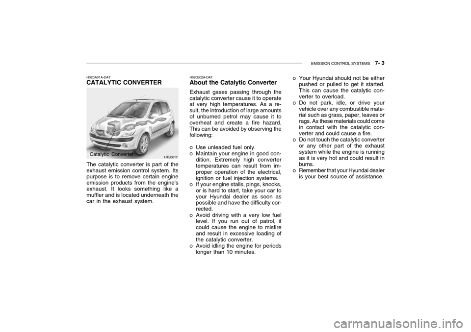
CATALYTIC CONVERTER
HTB5017
The catalytic converter is part of the exhaust emission control system. Its purpose is to remove certain engine emission products from the engine'sexhaust. It looks something like a muffler and is located underneath the car in the exhaust system.
Catalytic Converter H020B02A-DAT
About the Catalytic Converter
Exhaust gases passing through the
catalytic converter cause it to operate at very high temperatures. As a re- sult, the introduction of large amountsof unburned petrol may cause it to overheat and create a fire hazard. This can be avoided by observing thefollowing:
o Use unleaded fuel only.
o Maintain your engine in good con- dition. Extremely high convertertemperatures can result from im- proper operation of the electrical, ignition or fuel injection systems.
o If your engine stalls, pings, knocks,
or is hard to start, take your car toyour Hyundai dealer as soon as possible and have the difficulty cor- rected.
o Avoid driving with a very low fuel level. If you run out of patrol, itcould cause the engine to misfireand result in excessive loading of the catalytic converter.
o Avoid idling the engine for periods longer than 10 minutes. o Your Hyundai should not be either
pushed or pulled to get it started. This can cause the catalytic con-verter to overload.
o Do not park, idle, or drive your vehicle over any combustible mate- rial such as grass, paper, leaves or rags. As these materials could comein contact with the catalytic con- verter and could cause a fire.
o Do not touch the catalytic converter or any other part of the exhaustsystem while the engine is running as it is very hot and could result inburns.
o Remember that your Hyundai dealer is your best source of assistance.
Page 177 of 191

8. CONSUMER INFORMATION
Vehicle Identification Number (VIN) ................................................. 8-2
Engine number ................................................................................. 8-2
Recommended inflation pressures ................................................... 8-3
Snow tyres ....................................................................................... 8-4
Tyre chains ...................................................................................... 8-4
Tyre rotation ..................................................................................... 8-4
Tyre balancing .................................................................................. 8-5
Tyre traction ..................................................................................... 8-5
When to replace tyres ...................................................................... 8-5
Spare tyre and tools ......................................................................... 8-8
8