2009 Hyundai Accent fuel
[x] Cancel search: fuelPage 210 of 266

6
DO-IT-YOURSELF MAINTENANCE
5
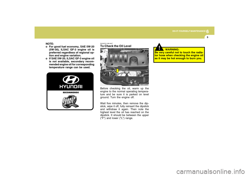
G030C01JM-AATTo Check the Oil LevelBefore checking the oil, warm up the
engine to the normal operating tempera-
ture and be sure it is parked on level
ground. Turn the engine off.
Wait five minutes, then remove the dip-
stick, wipe it off, fully reinsert the dipstick
and withdraw it again. Then note the
highest level the oil has reached on the
dipstick. It should be between the upper
("F") and lower ("L") range.
OMC059003
NOTE:
o For good fuel economy, SAE 5W-20
(5W-30), ILSAC GF-3 engine oil is
preferred regardless of regional op-
tion and engine variation.
o If SAE 5W-20, ILSAC GF-3 engine oil
is not available, secondary recom-
mended engine oil for corresponding
temperature range can be used.
!
WARNING:
Be very careful not to touch the radia-
tor hose when checking the engine oil
as it may be hot enough to burn you.
Page 233 of 266

6
DO-IT-YOURSELF MAINTENANCE
28
FUSE PANEL DESCRIPTION
FUSE RATING
125A
50A
40A
40A
40A
40A
30A
30A
30A
30A
30A
20A
15A
10A
10A
10A
10A
10A
30A
G200C01MC-AATEngine CompartmentNOTE:
Not all fuse panel descriptions in this manual may be applicable to your vehicle. It is accurate at the time of printing. When you
inspect the fuse box on your vehicle, refer to the fuse box label.
CIRCUIT PROTECTED
Generator
I/P Junction Box
Blower Relay, Blower Motor
ABS Control Module, Multipurpose Check Connector
ABS Control Module, Multipurpose Check Connector
Star t Relay, Ignition Switch
Ignition Switch
I/P Junction Box, Tail Lamp Relay
I/P Junction Box, Power Window Relay
Radiator Fan Relay
Main Relay, Fuel Pump Relay
ECM, PCM
Injector #1, #2, #3, #4, CVVT Oil Control Valve, Immobilizer Control Module,Purge
Control Solenoid Valve, Idle Speed Control Actuator, Fuel Pump Relay
A/Con Relay
A/C Control Module
ECM, PCM
Horn Relay, Burglar Alarm Horn Relay
A/Con Relay, Rad Fan Relay, Cond Fan Relay #1, #2, Camshaft Position
Sensor,Oxygen Sensor(UP, DOWN), Mass Air Flow Sensor
Condenser Fan Relay #1
MAIN
BATT #1
BLOWER
ABS #1
ABS #2
IGN #2
IGN #1
BATT #2
P/WDW
RAD
ECU A
ECU C
INJ
A/CON #1
A/CON #2
ECU B
HORN
SNSR
CONDFUSE
G200C01MC
Page 237 of 266

7
EMISSION CONTROL SYSTEMS2
EMISSION CONTROL SYSTEM
CanisterFuel vapors generated inside the fuel
tank are absorbed and stored in the
onboard canister. When the engine is
running, the fuel vapors absorbed in the
canister are drawn into the induction sys-
tem through the purge control solenoid
valve.Purge Control Solenoid Valve (PCSV)The purge control solenoid valve is con-
trolled by the Engine Control Module
(ECM); when the engine coolant tem-
perature is low during idling, the PCSV
closes so that evaporated fuel is not taken
into the engine. After the engine warms-
up during ordinary driving, the PCSV
opens to introduce evaporated fuel to the
engine.
H010B01A-AAT1. Crankcase Emission Control
SystemThe positive crankcase ventilation sys-
tem is employed to prevent air pollution
caused by blow-by gases being emitted
from the crankcase. This system supplies
filtered fresh air to the crankcase through
the air intake hose. Inside the crankcase,
the fresh air mixes with blow-by gases,
then passes through the PCV valve into
the induction system.
H010A01A-AATYour Hyundai is equipped with an emis-
sion control system to meet all require-
ments of the U.S. Environmental Protec-
tion Agency or California Air Resources
Board.
There are three emission control systems
which are as follows.
1) Crankcase Emission Control System
2) Evaporative Emission Control System
3) Exhaust Emission Control System
In order to ensure the proper function of
the emission control systems, it is recom-
mended that you have your car inspected
and maintained by an authorized Hyundai
dealer in accordance with the mainte-
nance schedule in this manual.
H010D01A-AAT3. Exhaust Emission
Control SystemThe Exhaust Emission Control System is
a highly effective system which controls
exhaust emissions while maintaining
good vehicle performace.
H010C01S-AAT2. Evaporative Emission Control (In-
cluding ORVR: Onboard Refuel-
ing Vapor Recovery) SystemThe Evaporative Emission Control Sys-
tem is designed to prevent fuel vapors
from escaping into the atmosphere.
(The ORVR system is designed to allow
the vapors from the fuel tank to be loaded
into a canister while refueling at the gas
station, preventing the escape of fuel
vapors into the atmosphere.)
Page 238 of 266

7
EMISSION CONTROL SYSTEMS
3
CATALYTIC CONVERTER
!
!
H020A03A-AAT(If Installed)Hyundai vehicle is equipped with a mono-
lith type three-way catalytic converter to
reduce the carbon monoxide, hydrocar-
bons and nitrogen oxides contained in
the exhaust gas. Exhaust gases passing
through the catalytic converter cause it to
operate at a very high temperature. The
introduction of large amounts of unburned
gasoline into the exhaust may cause the
catalytic converter to overheat and create
a fire hazard. This risk may be reduced by
observing the following:WARNING:
o Do not touch the catalytic converter
or any other part of the exhaust sys-
tem while the catalytic converter is
hot. Shut off the engine, wait for at
least one hour before touching the
catalytic converter or any other part
of the exhaust system.
o Remember that your Hyundai dealer
is your best source of assistance.
o Do not park, idle or drive your ve-
hicle over any combustible material
such as grass, paper, leaves or rags.
These materials might contact the
hot catalytic converter and a fire
might result.
H020A01MC
Catalytic Converter
WARNING:
o Use unleaded fuel only.
o Maintain the engine in good operat-
ing condition. Extremely high cata-
lytic converter temperatures can re-
sult from improper operation of the
electrical, ignition or multiport elec-
tronic fuel injection.
o If your engine stalls, pings, knocks,
or is hard to start, have your Hyundai
dealer inspect and repair the prob-
lem as soon as possible.
o Avoid driving with a very low fuel
level. Running out of gasoline may
cause the engine to misfire and re-
sult in damage to the catalytic con-
verter.
o Avoid idling the engine for periods
longer than 10 minutes.
o The vehicle should not be pushed or
pulled to get started. This may cause
the catalytic converter to overheat
and create a fire hazard.
Page 243 of 266

8
CONSUMER INFORMATION, REPORTING SAFETY DEFECTS & BINDING ARBITRATION OF WARRANTY CLAIMS
5
!
!
o Worn tires can cause accidents.
Replace tires that are worn, show
uneven wear, or are damaged.
See page 8-12.
o Remember to check the pressure
of your spare tire. Hyundai rec-
ommends that you check the
spare every time you check the
pressure of the other tires on
your vehicle.
WARNING:
Overinflation or underinflation can
reduce the tire life, adversely affect
vehicle handling, and lead to sud-
den tire failure. This could rusult in
loss of vehicle control and potential
injury.CAUTION:
Always observe the following:
o Check pressures when the tires
are cold. (After the vehicle has
been parked for at least three
hours or hasn't been driven more
than one mile (1.6 km) since start-
ing up.)
o Check the pressure of your spare
tire each time you check the pres-
sure of other tires.
o Never overload your vehicle. Be
especially careful about overload-
ing if you equip your vehicle with
a luggage rack.
o Worn, old tires can cause acci-
dents. If your tread is badly worn,
or if your tires have been dam-
aged, replace them.
!
WARNING:NOTE:
o Underinflation also results in ex-
cessive wear, poor handling and
reduced fuel economy. Wheel de-
formation also is possible. Keep
your tire pressures at the proper
levels. If a tire frequently needs
refilling, have it checked by your
Hyundai Dealer.
o Overinflation produces a harsh
ride, excessive wear at the center
of the tire tread, and a greater
possibility of damage from road
hazards.
Page 246 of 266

8
CONSUMER INFORMATION, REPORTING SAFETY DEFECTS & BINDING ARBITRATION OF WARRANTY CLAIMS8
I030D01JM-AATTIRE TERMINOLOGY AND DEFINI-
TIONS
Air Pressure: The amount of air inside
the tire pressing outward on the tire.
Air pressure is expressed in pounds
per square inch (psi) or kilopascal (kPa).
Accessory Weight: This means the
combined weight of optional accesso-
ries. Some examples of optional ac-
cessories are, automatic transmission,
power seats, and air conditioning.
Aspect Ratio: The relationship of a
tire's height to its width.
Belt: A rubber coated layer of cords
that is located between the plies and
the tread. Cords may be made from
steel or other reinforcing materials.
Bead: The tire bead contains steel
wires wrapped by steel cords that hold
the tire onto the rim.
Bias Ply Tire: A pneumatic tire in
which the plies are laid at alternate
angles less than 90 degrees to the
centerline of the tread.Cold Tire Pressure: The amount of
air pressure in a tire, measured in
pounds per square inch (psi) or
kilopascals (kPa) before a tire has
built up heat from driving.
Curb Weight: This means the weight
of a motor vehicle with standard and
optional equipment including the maxi-
mum capacity of fuel, oil and coolant,
but without passengers and cargo.
DOT Markings: A code molded into
the sidewall of a tire signifying that the
tire is in compliance with the U.S.
Department of Transportation motor
vehicle safety standards. The DOT
code includes the Tire Identification
Number (TIN), an alphanumeric desig-
nator which can also identify the tire
manufacturer, production plant, brand
and date of production.
GVWR: Gross Vehicle Weight Rating
GAWR FRT: Gross Axle Weight Rat-
ing for the front Axle.
GAWR RR: Gross Axle Weight Rating
for the rear axle. 6. Maximum load rating
This number indicates the maxi-
mum load in kilograms and pounds
that can be carried by the tire. When
replacing the tires on the vehicle,
always use a tire that has the same
load rating as the factory installed
tire.
7. Uniform Tire Quality Grading
(UTQG):
Tire manufacturers are required to
grade tires based on three perfor-
mance factors: treadwear, traction
and temperature resistance. For
more information, see Uniform Tire
Quality Grading on page 8-15.
Page 258 of 266

9
VEHICLE SPECIFICATIONS2
Tire Size
P175/70 R14, P185/65 R14, P195/55 R15
P175/70 R14, P185/65 R14, P205/45 R16
T115/70 D15
in. (mm)
Liter
45
Dual hydraulic with brake booster
Ventilated disc
Drum
Cable operated on rear wheel
4Door
3Door
Spare
US. gal
11.9 Fuel tank capacityImp.gal
9.9
Type
Front brake type
Rear brake type
Parking brake
Inflation Pressure
32PSI (220 kPa)
60PSI (420 kPa)
J010A03MC-AATMEASUREMENTJ020A01MC-AATPOWER STEERING
J060A01A-AATFUEL SYSTEMJ050A02MC-AATBRAKEJ030A03MC-AATTIRE
4 DOOR
168.5 (4280)
66.7 (1695)
57.8 (1470)
98.4 (2500)
57.8 (1470) / 58.4 (1485)*
57.4 (1460) / 58 (1475)* Item
Overall length
Overall width
Overall height
Wheel base
Wheel tread
Front
Rear
3 DOOR
159.2 (4045)
Type
Wheel free play
Rack stroke
Oil pump type
Rack and pinion
0 ~ 1.18 in (0 ~ 30 mm)
5.59 in. (142 mm)
5.43 in. (138 mm)
Vane type
175 Tire only
Except 175 Tire
* with P175/70R14 Tire
Page 263 of 266

10
INDEX
3
D
Defrosting/Defogging........................................... 1-112, 1-115
Door
Central door locks ............................................................ 1-7
Door locks ......................................................................... 1-4
Door ajar warning light and chime ................................1-66
Locking and unlocking front door with a key .................. 1-5
Drink Holder .......................................................................1-84
Driving
Economical driving .........................................................2-15
Smooth cornering ...........................................................2-16
Winter driving ..................................................................2-16
E
Emission Control System ..................................................... 7-2
Engine
Before starting the engine ................................................ 2-3
Compartment.................................................................... 6-2
Coolant .............................................................................. 6-7
If the engine overheats ..................................................... 3-4
Number............................................................................. 8-3
Oil ...................................................................................... 6-4
Starting.............................................................................. 2-5
Engine Exhaust Can Be Dangerous! .................................. 2-2F
Fog Light
Front ................................................................................1-82
Front Seats
Adjusting seat forward and rearward ............................1-14
Adjusting seatback angle ...............................................1-15
Headrest..........................................................................1-15
Seat cushion height adjustment ................................... 1-17
Fuel
Capacity............................................................................ 9-2
Gauge..............................................................................1-70
Recommendations............................................................ 1-2
Fuel Filler Lid
Remote release ..............................................................1-94
Fuse Panel Description .....................................................6-28
Fuses..................................................................................6-16
G
General Checks ................................................................... 6-3
Glove Box ...........................................................................1-88
H
Hazard Warning System ....................................................1-81
Headlight
Replacement...................................................................6-22
Switch..............................................................................1-76