2009 Hyundai Accent fuel cap
[x] Cancel search: fuel capPage 64 of 232
1
FEATURES OF YOUR HYUNDAI
53
If the Emission Control System Mal- function Indicator Light begins toflash ON and OFF, potential catalytic converter damage is possible which could result in loss of engine power.Have the Engine Control System in- spected as soon as possible by an authorised Hyundai dealer.
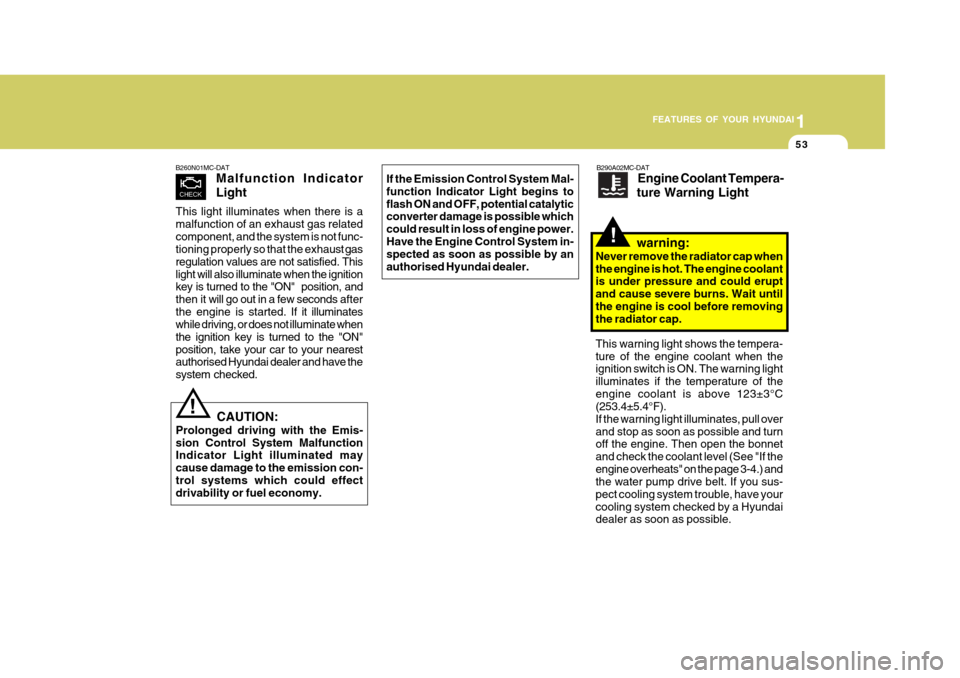
B260N01MC-DAT Malfunction Indicator Light
This light illuminates when there is a malfunction of an exhaust gas relatedcomponent, and the system is not func- tioning properly so that the exha ust gas
regulation values are not satisfied. This light will also illuminate when the ignition
key is turned to the "ON" position, and then it will go out in a few seconds after
the engine is started. If it illuminates
while driving, or does not illuminate whenthe ignition key is turned to the "ON"position, take your car to your nearest
authorised Hyundai dealer and have the system checked.
CAUTION:
Prolonged driving with the Emis- sion Control System Malfunction Indicator Light illuminated may cause damage to the emission con-trol systems which could effect drivability or fuel economy.!
B290A02MC-DAT Engine Coolant Tempera-
ture Warning Light
warning:
Never remove the radiator cap when the engine is hot. The engine coolant is under pressure and could erupt and cause severe burns. Wait untilthe engine is cool before removing the radiator cap.
!
This warning light shows the tempera- ture of the engine coolant when the ignition switch is ON. The warning light illuminates if the temperature of theengine coolant is above 123±3°C (253.4±5.4°F). If the warning light illuminates, pull overand stop as soon as possible and turn off the engine. Then open the bonnet and check the coolant level (See "If theengine overheats" on the page 3-4.) and the water pump drive belt. If you sus- pect cooling system trouble, have yourcooling system checked by a Hyundai dealer as soon as possible.
Page 66 of 232
1
FEATURES OF YOUR HYUNDAI
55INSTRUMENT CLUSTER
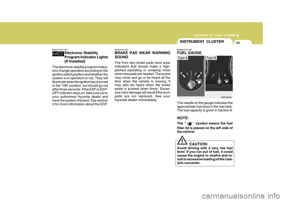
The needle on the gauge indicates the approximate fuel level in the fuel tank. The fuel capacity is given in Section 9. NOTE: The "
" symbol means the fuel
filler lid is placed on the left side of the vehicle.
B280A02TG-AAT FUEL GAUGE
OMC029420
Type AType B
B270A01A-AAT BRAKE PAD WEAR WARNING SOUND The front disc brake pads have wear indicators that should make a high-pitched squealing or scraping noise when new pads are needed. The sound may come and go or be heard all thetime when the vehicle is moving. It may also be heard when the brake pedal is pushed down firmly. Exces-sive rotor damage will result if the worn pads are not replaced. See your Hyundai dealer immediately.
B265C01NF-DAT
Electronic Stability Program Indicator Lights(If Installed)
The electronic stability program indica- tors change operation according to the ignition switch position and whether thesystem is in operation or not. They will illuminate when the ignition key is turned to the "ON" position, but should go outafter three seconds. If the ESP or ESP- OFF indicator stays on, take your car to your authorised Hyundai dealer andhave the system checked. See section 2 for more information about the ESP.
CAUTION:
Avoid driving with a very low fuel level. If you run out of fuel, it could cause the engine to misfire and re-sult in excessive loading of the cata- lytic converter.!
Page 92 of 232
1
FEATURES OF YOUR HYUNDAI
81
!WARNING:
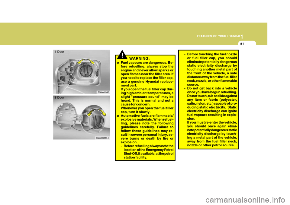
o Fuel vapours are dangerous. Be- fore refuelling, always stop the engine and never allow sparks oropen flames near the filler area. If you need to replace the filler cap, use a genuine Hyundai replace-ment part. If you open the fuel filler cap dur- ing high ambient temperatures, aslight "pressure sound" may be heard. This is normal and not a cause for concern. Whenever you open the fuel filler cap, turn it slowly.
o Automotive fuels are flammable/ explosive materials. When refuel-ling, please note the followingguidelines carefully. Failure to follow these guidelines may re- sult in severe personal injury, se-vere burns or death by fire or explosion.
- Before refuelling always note the
location of the Emergency Petrol Shut-Off, if available, at the petrol station facility.
B560A02MC
4 Door
B560A02MC-1
3 Door
- Before touching the fuel nozzle
or fuel filler cap, you should eliminate potentially dangerous static electricity discharge by touching another metal part ofthe front of the vehicle, a safe distance away from the fuel filler neck, nozzle, or other flammablesource.
- Do not get back into a vehicle
once you have begun refuelling.Do not touch, rub or slide against any item or fabric (polyester, satin, nylon, etc.) capable of pro-ducing static electricity. Static electricity discharge can ignite fuel vapours resulting in explo-sion. If you must re-enter the vehicle, you should once again elimi-nate potentially dangerous static electricity discharge by touch- ing a metal part of the vehicle,away from the fuel filler neck, nozzle or other petrol source.
Page 93 of 232
1FEATURES OF YOUR HYUNDAI
82
!
BOOT LID / TAIL GATE
B540A01MC-DAT
WARNING:
The boot lid or tail gate should always be kept completely closedwhile the vehicle is in motion. If it is left open or ajar, poisonous ex- haust gases may enter the car re-sulting in serious injury or death to the occupants. See additional warn- ings concerning exhaust gases onpage 2-2.
- When using a portable fuel con- tainer be sure to place the con- tainer on the ground prior to refuelling. Static electricity dis- charge from the container canignite fuel vapours causing a fire. Once refuelling has begun, contact with the vehicle shouldbe maintained until the filling is complete. Use only portable fuel containers designed to carry andstore petrol.
- Do not use mobile phones
around a petrol station or whilerefuelling any vehicle. Electric current and/or electronic inter- ference from mobile phones canpotentially ignite fuel vapours causing a fire. If you must use your mobile phone use it in aplace away from the petrol sta- tion.- When refuelling always shut theengine off. Sparks produced by electrical components related tothe engine can ignite fuel vapours causing a fire. Always insure that the engine is OFF before andduring refuelling. Once refuel- ling is complete, check to make sure the fuel filler cap and doorare securely closed, before start- ing the engine.
- Do not light any fire around a petrol station. DO NOT usematches or a lighter and DO NOT SMOKE or leave a lit ciga-rette in your vehicle while at a petrol station especially during refuelling. Automotive fuel ishighly flammable and can, when ignited, result in explosion by flames.
- If a fire breaks out during refuel- ling, leave the vicinity of thevehicle, and immediately con-tact the manager of the petrol station or contact the police and local fire department. Followany safety instructions they pro- vide.
Page 176 of 232
5VEHICLE MAINTENANCE REQUIREMENTS
4REGULAR SERVICING
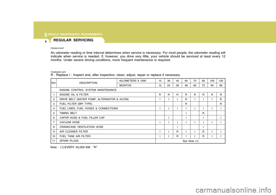
F030A01A-DAT An odometer reading or time interval determines when service is necessary. For most people, the odometer reading will indicate when service is needed. If, however, you drive very little, your vehicle should be serviced at least every 12 months. Under severe driving conditions, more frequent maintenance is required.
F030B02MC-GAT R : Replace I : Inspect and, after inspection, clean, adjust, repair or replace if necessary
ENGINE CONTROL SYSTEM MAINTENANCE
1 ENGINE OIL & FILTER
2 DRIVE BELT (WATER PUMP, ALTERNATOR & A/CON)
3 FUEL FILTER (MPI TYPE)
4 FUEL LINES, FUEL HOSES & CONNECTIONS
5 TIMING BELT
6 VAPOR HOSE & FUEL FILLER CAP
7 VACUUM HOSE
8 CRANKCASE VENTILATION HOSE
9 AIR CLEANER FILTER
10 FUEL TANK AIR FILTER
11 SPARK PLUGS
NO. DESCRIPTION105
84
R I I I I I 120
96
RR R I I I I I
90 72
R I I
R I I I
RR
75 60
R I I I I I
60 48
R R R II I I I I
45 36
R I I I I
RR
30 24
R I II I I I
15 12
R I I I I I
KILOMETERS X 1000 MONTHS
Note : (1) EVERY 40,000 KM : "R"
See Note (1)
Page 179 of 232
5
VEHICLE MAINTENANCE REQUIREMENTS
7EXPLANATION OF SCHED- ULED MAINTENANCE ITEMS
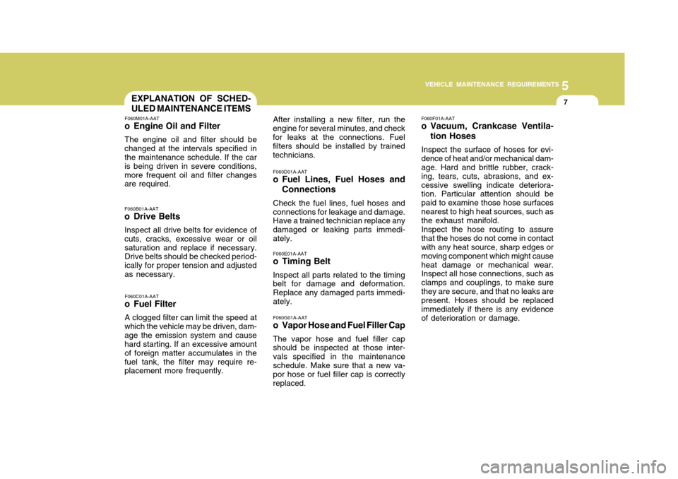
F060M01A-AAT
o Engine Oil and Filter
The engine oil and filter should be
changed at the intervals specified in the maintenance schedule. If the car is being driven in severe conditions,more frequent oil and filter changes are required. F060B01A-AAT
o Drive Belts
Inspect all drive belts for evidence of cuts, cracks, excessive wear or oilsaturation and replace if necessary. Drive belts should be checked period- ically for proper tension and adjustedas necessary. After installing a new filter, run the
engine for several minutes, and checkfor leaks at the connections. Fuel filters should be installed by trained technicians.
F060D01A-AAT
o Fuel Lines, Fuel Hoses and Connections
Check the fuel lines, fuel hoses and connections for leakage and damage. Have a trained technician replace any damaged or leaking parts immedi-ately. F060E01A-AAT
o Timing Belt Inspect all parts related to the timing belt for damage and deformation. Replace any damaged parts immedi-ately. F060G01A-AAT
o Vapor Hose and Fuel Filler Cap The vapor hose and fuel filler cap should be inspected at those inter- vals specified in the maintenanceschedule. Make sure that a new va- por hose or fuel filler cap is correctly replaced. F060F01A-AAT
o Vacuum, Crankcase Ventila-
tion Hoses
Inspect the surface of hoses for evi- dence of heat and/or mechanical dam- age. Hard and brittle rubber, crack- ing, tears, cuts, abrasions, and ex-cessive swelling indicate deteriora- tion. Particular attention should be paid to examine those hose surfacesnearest to high heat sources, such as the exhaust manifold. Inspect the hose routing to assure that the hoses do not come in contact with any heat source, sharp edges or moving component which might causeheat damage or mechanical wear. Inspect all hose connections, such as clamps and couplings, to make surethey are secure, and that no leaks are present. Hoses should be replaced immediately if there is any evidenceof deterioration or damage.
F060C01A-AAT
o Fuel Filter
A clogged filter can limit the speed at
which the vehicle may be driven, dam-age the emission system and cause hard starting. If an excessive amount of foreign matter accumulates in thefuel tank, the filter may require re- placement more frequently.
Page 215 of 232
7EMISSION CONTROL SYSTEMS
2EMISSION CONTROL SYS- TEM
H010A01A-DAT Your Hyundai is equipped with an
emission control system to meet all Australian Design Rules(ADR) require- ments.
There are three emission control sys-
tems which are as follows.
1. Crankcase emission control sys-
tem
2. Evaporative emission control sys-
tem
3. Exhaust emission control system
In order to assure the proper function
of the emission control systems, it is recommended that you have your carinspected and maintained by an authorised Hyundai dealer in accor- dance with the maintenance schedulein this manual. H010B01A-AAT
1. Crankcase Emission Control
System
The positive crankcase ventilation
(PCV) system is employed to prevent air pollution caused by blow-by gases being emitted from the crankcase.This system supplies fresh air to the crankcase through the air intake hose. Inside the crankcase, the fresh airmixes with blow-by gases, which then pass through the PCV valve and into the induction system.
H010C03Y-DAT
2. Evaporative Emission Control
System
The Evaporative Emission Control
System is designed to prevent fuelvapours from escaping into the atmo- sphere. H010D01A-AAT
3. Exhaust Emission Control
System
The exhaust emission control system
is a highly effective system whichcontrols exhaust emission while main- taining good vehicle performance.
Canister
Fuel vapors generated inside the fuel
tank are absorbed and stored in theonboard canister. When the engine isrunning, the fuel vapors absorbed in the canister are drawn into the surge tank system through the purge controlsolenoid valve. Purge Control Solenoid Valve
The purge control solenoid valve is
controlled by the ECM (Engine Control Module); when the engine coolant tem- perature is low, and during idling, it closes, so that evaporated fuel is not taken into the engine. After engine warm-up, during ordinary driving, itopens so as to introduce evaporated fuel to the engine.
Page 225 of 232
9 VEHICLE SPECIFICATIONS
2
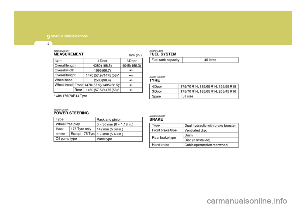
Type Wheel free play Rackstroke Oil pump type J030A01MC-DAT TYRE
Dual hydraulic with brake booster Ventilated disc DrumDisc (If Installed) Cable operated on rear wheel
J060A01A-DAT FUEL SYSTEM
Rack and pinion 0 ~ 30 mm (0 ~ 1.18 in.) 142 mm (5.59 in.)138 mm (5.43 in.) Vane type
175/70 R14, 185/65 R14, 195/55 R15 175/70 R14, 185/65 R14, 205/45 R16 Full size
4 Door3 Door Spare
J020A01MC-DAT POWER STEERING Fuel tank capacity 45 litres
J050A02MC-DATBRAKE Type Front brake type Rear brake typeHand brake
175 Tyre only Except 175 Tyre
4 Door
4280 (168.5)
1695 (66.7)
1470 (57.9)/1475 (58)* 2500 (98.4)
1470 (57.9)/1485 (58.5)*
1460 (57.5)/1475 (58)*
Item Overall length Overall width Overall heightWheel base Wheel tread
J010A02MC-DAT MEASUREMENT
Front Rear
mm (in.)
3 Door
4045 (159.3)
* with 175/70R14 Tyre