Page 282 of 358

Fuse/Relay
LocationFuse Amp
RatingProtected Circuits
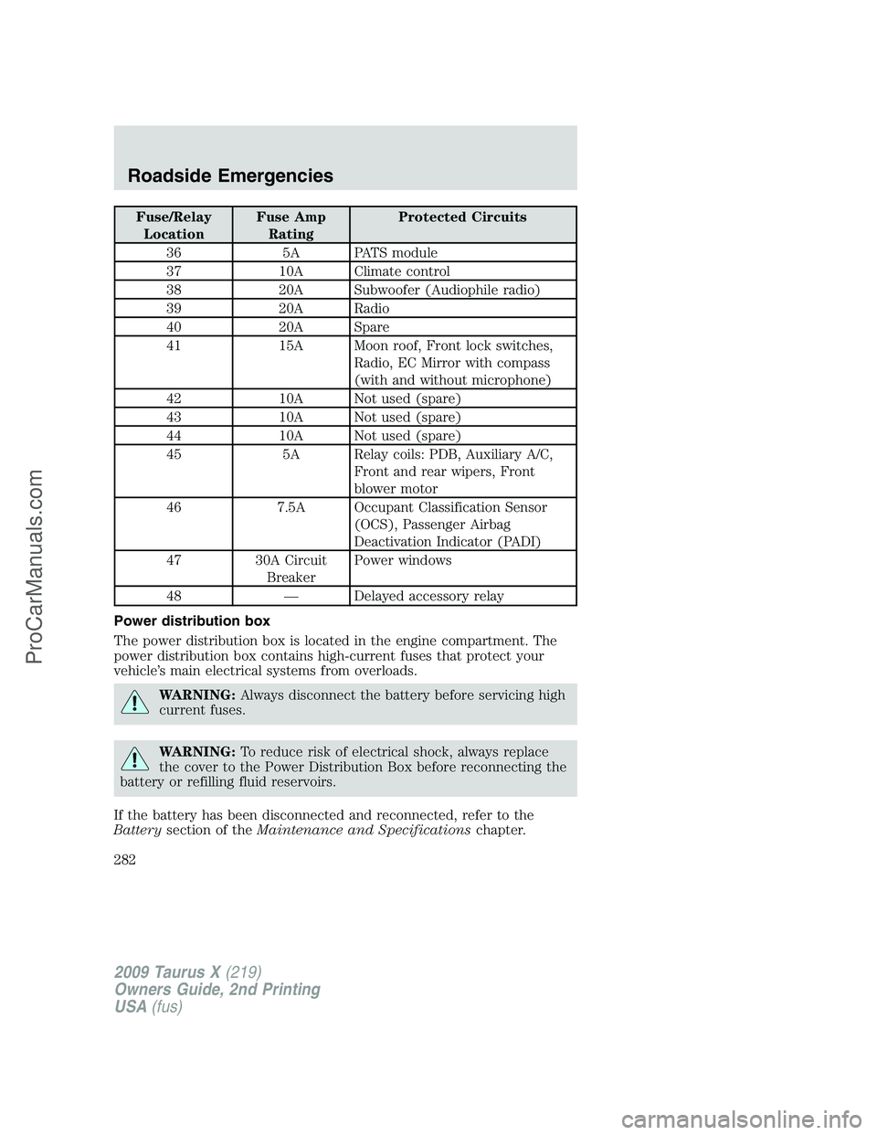
36 5A PATS module
37 10A Climate control
38 20A Subwoofer (Audiophile radio)
39 20A Radio
40 20A Spare
41 15A Moon roof, Front lock switches,
Radio, EC Mirror with compass
(with and without microphone)
42 10A Not used (spare)
43 10A Not used (spare)
44 10A Not used (spare)
45 5A Relay coils: PDB, Auxiliary A/C,
Front and rear wipers, Front
blower motor
46 7.5A Occupant Classification Sensor
(OCS), Passenger Airbag
Deactivation Indicator (PADI)
47 30A Circuit
BreakerPower windows
48 — Delayed accessory relay
Power distribution box
The power distribution box is located in the engine compartment. The
power distribution box contains high-current fuses that protect your
vehicle’s main electrical systems from overloads.
WARNING:Always disconnect the battery before servicing high
current fuses.
WARNING:To reduce risk of electrical shock, always replace
the cover to the Power Distribution Box before reconnecting the
battery or refilling fluid reservoirs.
If the battery has been disconnected and reconnected, refer to the
Batterysection of theMaintenance and Specificationschapter.
2009 Taurus X(219)
Owners Guide, 2nd Printing
USA(fus)
Roadside Emergencies
282
ProCarManuals.com
Page 283 of 358
The high-current fuses are coded as follows:
Fuse/Relay
LocationFuse Amp
RatingProtected Circuits
1 80A* SPDJB power
2 80A* SPDJB power
3 30A* Front wipers
4 — Not used
5 20A* Rear heated seat module
6 — Not used
7 50A* Engine cooling fan
8 — Not used
9 40A* Anti-lock Brake System
(ABS)/AdvanceTrac pump
10 30A* Starter
11 50A* Powertrain Control Module (PCM)
relay
12 20A* ABS/AdvanceTrac valve
13 20A** Power point (instrument panel)
14 20A** Power point (2nd row)
15 20A** Power point (3rd row)
2009 Taurus X(219)
Owners Guide, 2nd Printing
USA(fus)
Roadside Emergencies
283
ProCarManuals.com
Page 288 of 358

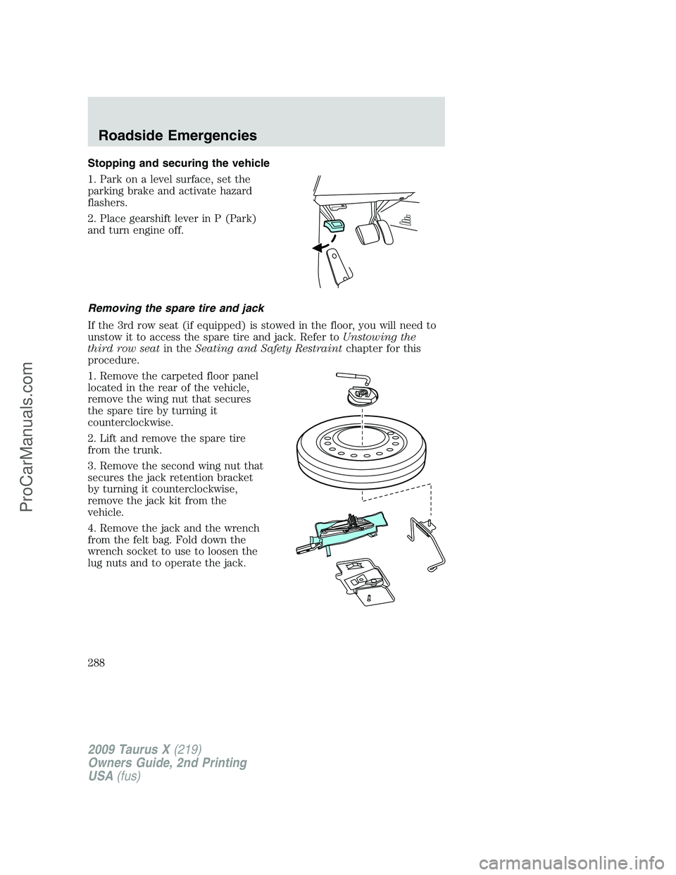
Stopping and securing the vehicle
1. Park on a level surface, set the
parking brake and activate hazard
flashers.
2. Place gearshift lever in P (Park)
and turn engine off.
Removing the spare tire and jack
If the 3rd row seat (if equipped) is stowed in the floor, you will need to
unstow it to access the spare tire and jack. Refer toUnstowing the
third row seatin theSeating and Safety Restraintchapter for this
procedure.
1. Remove the carpeted floor panel
located in the rear of the vehicle,
remove the wing nut that secures
the spare tire by turning it
counterclockwise.
2. Lift and remove the spare tire
from the trunk.
3. Remove the second wing nut that
secures the jack retention bracket
by turning it counterclockwise,
remove the jack kit from the
vehicle.
4. Remove the jack and the wrench
from the felt bag. Fold down the
wrench socket to use to loosen the
lug nuts and to operate the jack.
2009 Taurus X(219)
Owners Guide, 2nd Printing
USA(fus)
Roadside Emergencies
288
ProCarManuals.com
Page 290 of 358

WARNING:To lessen the risk of personal injury, do not put any
part of your body under the vehicle while changing a tire. Do not
start the engine when your vehicle is on the jack. The jack is only
meant for changing the tire.
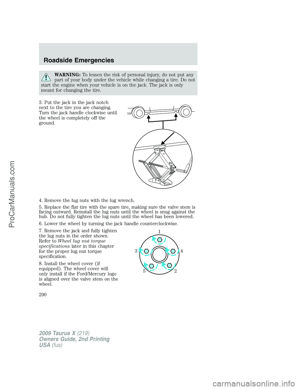
3. Put the jack in the jack notch
next to the tire you are changing.
Turn the jack handle clockwise until
the wheel is completely off the
ground.
4. Remove the lug nuts with the lug wrench.
5. Replace the flat tire with the spare tire, making sure the valve stem is
facing outward. Reinstall the lug nuts until the wheel is snug against the
hub. Do not fully tighten the lug nuts until the wheel has been lowered.
6. Lower the wheel by turning the jack handle counterclockwise.
7. Remove the jack and fully tighten
the lug nuts in the order shown.
Refer toWheel lug nut torque
specificationslater in this chapter
for the proper lug nut torque
specification.
8. Install the wheel cover (if
equipped). The wheel cover will
only install if the Ford/Mercury logo
is aligned over the valve stem on the
wheel.
1
4 3
2 5
2009 Taurus X(219)
Owners Guide, 2nd Printing
USA(fus)
Roadside Emergencies
290
ProCarManuals.com
Page 293 of 358

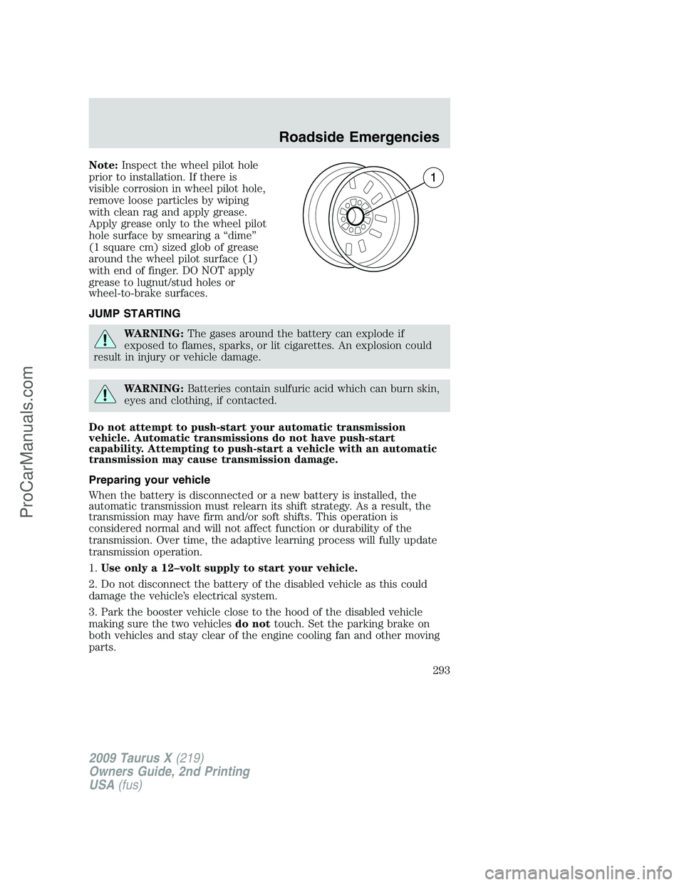
Note:Inspect the wheel pilot hole
prior to installation. If there is
visible corrosion in wheel pilot hole,
remove loose particles by wiping
with clean rag and apply grease.
Apply grease only to the wheel pilot
hole surface by smearing a “dime”
(1 square cm) sized glob of grease
around the wheel pilot surface (1)
with end of finger. DO NOT apply
grease to lugnut/stud holes or
wheel-to-brake surfaces.
JUMP STARTING
WARNING:The gases around the battery can explode if
exposed to flames, sparks, or lit cigarettes. An explosion could
result in injury or vehicle damage.
WARNING:Batteries contain sulfuric acid which can burn skin,
eyes and clothing, if contacted.
Do not attempt to push-start your automatic transmission
vehicle. Automatic transmissions do not have push-start
capability. Attempting to push-start a vehicle with an automatic
transmission may cause transmission damage.
Preparing your vehicle
When the battery is disconnected or a new battery is installed, the
automatic transmission must relearn its shift strategy. As a result, the
transmission may have firm and/or soft shifts. This operation is
considered normal and will not affect function or durability of the
transmission. Over time, the adaptive learning process will fully update
transmission operation.
1.Use only a 12–volt supply to start your vehicle.
2. Do not disconnect the battery of the disabled vehicle as this could
damage the vehicle’s electrical system.
3. Park the booster vehicle close to the hood of the disabled vehicle
making sure the two vehiclesdo nottouch. Set the parking brake on
both vehicles and stay clear of the engine cooling fan and other moving
parts.
2009 Taurus X(219)
Owners Guide, 2nd Printing
USA(fus)
Roadside Emergencies
293
ProCarManuals.com
Page 295 of 358
3. Connect the negative (-) cable to the negative (-) terminal of the
assisting battery.
4. Make the final connection of the negative (-) cable to an exposed
metal part of the stalled vehicle’s engine, away from the battery and the
carburetor/fuel injection system.Do notuse fuel lines, engine rocker
covers or the intake manifold asgroundingpoints.
WARNING:Do not connect the end of the second cable to the
negative (-) terminal of the battery to be jumped. A spark may
cause an explosion of the gases that surround the battery.
5. Ensure that the cables are clear of fan blades, belts, moving parts of
both engines, or any fuel delivery system parts.
+–+–
+–+–
2009 Taurus X(219)
Owners Guide, 2nd Printing
USA(fus)
Roadside Emergencies
295
ProCarManuals.com
Page 296 of 358
Jump starting
1. Start the engine of the booster vehicle and run the engine at
moderately increased speed.
2. Start the engine of the disabled vehicle.
3. Once the disabled vehicle has been started, run both engines for an
additional three minutes before disconnecting the jumper cables.
Removing the jumper cables
Remove the jumper cables in the reverse order that they were
connected.
1. Remove the jumper cable from thegroundmetal surface.
Note:In the illustrations,lightning boltsare used to designate the
assisting (boosting) battery.
2. Remove the jumper cable on the negative (-) connection of the
booster vehicle’s battery.
+–+–
+–+–
2009 Taurus X(219)
Owners Guide, 2nd Printing
USA(fus)
Roadside Emergencies
296
ProCarManuals.com
Page 297 of 358
3. Remove the jumper cable from the positive (+) terminal of the booster
vehicle’s battery.
4. Remove the jumper cable from the positive (+) terminal of the
disabled vehicle’s battery.
After the disabled vehicle has been started and the jumper cables
removed, allow it to idle for several minutes so the engine computer can
relearnits idle conditions.
+–+–
+–+–
2009 Taurus X(219)
Owners Guide, 2nd Printing
USA(fus)
Roadside Emergencies
297
ProCarManuals.com