2009 FORD F750 maintenance schedule
[x] Cancel search: maintenance schedulePage 3 of 276

Maintenance and Specifications 171
Hood 179
Engine oil 182
Battery 182
Engine coolant 184
Fuel information 186
Wheel lug nut torque 212
Tire information 212
Lubricant specifications 220
Refill capacities 232
Scheduled Maintenance Guide 237
Index 272
All rights reserved. Reproduction by any means, electronic or mechanical
including photocopying, recording or by any information storage and retrieval
system or translation in whole or part is not permitted without written
authorization from Ford Motor Company. Ford may change the contents without
notice and without incurring obligation.
Copyright © 2008 Ford Motor Company
Table of Contents
3
2009 F-650/750(f67)
Supplement
USA(fus)
Page 98 of 276

•Within the final 30 seconds, the timer can be reset by:
1. changing the position of the accelerator pedal, or
2. changing the brake pedal, clutch pedal, or park brake from engaged
to disengaged or from disengaged to engaged.
•When the timer reaches zero, the engine will shut down.
•In this event, the key remains in the ON (Run) position, and power
continues to be supplied to the accessories.
Battery power may be drained if the key is left in the ON (Run)
position without the engine running.
Note:The engine idle shutdown timer will not start if:
•The engine is operating in power take-off (PTO) mode.
•The engine coolant temperature is below 60° F (16° C).
•The exhaust emission control system is regenerating the diesel
particulate filter (DPF).
ENGINE AUTOMATIC SHUTDOWN WARNING LIGHT OR CHIME
(IF EQUIPPED)
Your vehicle may be equipped with an automatic shutdown feature that
stops the engine in the event of high coolant temperature, low engine oil
pressure, high diesel particulate filter soot loading or low engine coolant
level. A warning light in the instrument cluster and a warning chime will
indicate high engine coolant temperature, low engine oil pressure or the
need to have the diesel particulate filter cleaned or serviced. If the
engine coolant temperature becomes too high, engine oil pressure too
low or the diesel particulate filter too restricted, the engine will
automatically shut down.
If the engine shuts down, it can be restarted and operated for
30 seconds at a time or until the problem is corrected. Do not attempt to
use this restarting feature to drive the vehicle very far as serious engine
damage could result.
WARNING:In the event of engine shutdown, make sure the
vehicle is safely off the road and the problem is remedied prior
to returning to the road. Failure to remove the vehicle from the road
could result in an accident, causing serious injury or death.
GENERAL BRAKE INFORMATION
All standard equipment brakes are designed to be self-adjusting.
Automatic adjustment, when required, occurs whenever the brakes are
applied and released during forward or reverse operation. Refer to the
Scheduled Maintenance Guidechapter for scheduled maintenance.
2009 F-650/750(f67)
Supplement
USA(fus)
Driving
98
Page 107 of 276

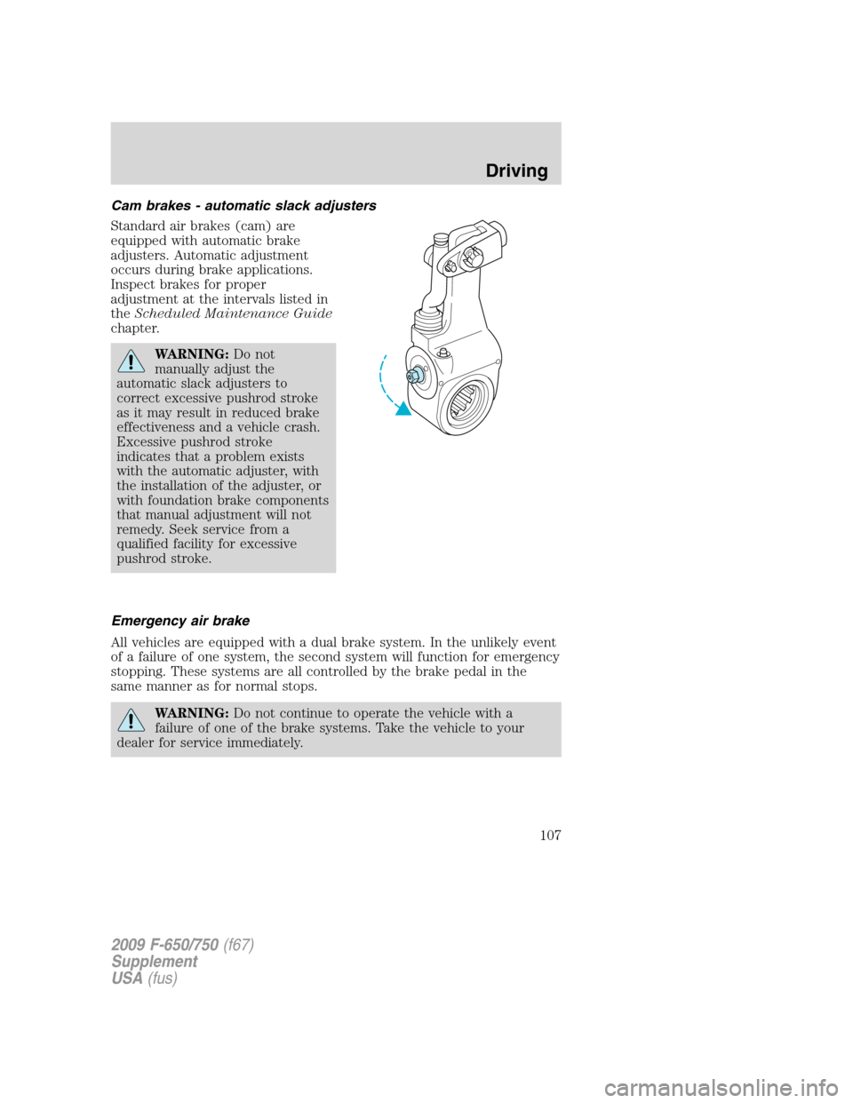
Cam brakes - automatic slack adjusters
Standard air brakes (cam) are
equipped with automatic brake
adjusters. Automatic adjustment
occurs during brake applications.
Inspect brakes for proper
adjustment at the intervals listed in
theScheduled Maintenance Guide
chapter.
WARNING:Do not
manually adjust the
automatic slack adjusters to
correct excessive pushrod stroke
as it may result in reduced brake
effectiveness and a vehicle crash.
Excessive pushrod stroke
indicates that a problem exists
with the automatic adjuster, with
the installation of the adjuster, or
with foundation brake components
that manual adjustment will not
remedy. Seek service from a
qualified facility for excessive
pushrod stroke.
Emergency air brake
All vehicles are equipped with a dual brake system. In the unlikely event
of a failure of one system, the second system will function for emergency
stopping. These systems are all controlled by the brake pedal in the
same manner as for normal stops.
WARNING:Do not continue to operate the vehicle with a
failure of one of the brake systems. Take the vehicle to your
dealer for service immediately.
2009 F-650/750(f67)
Supplement
USA(fus)
Driving
107
Page 126 of 276

CLUTCH (IF EQUIPPED)
Do not ride or slip the clutch as this will cause unnecessary heat and
wear. Maintain the specified clutch adjustment to prolong its life and
regularly inspect the clutch control linkage for tightness. Refer to the
Scheduled Maintenance Guidechapter for other maintenance
information. When adjustment of the clutch is necessary, it is very
important that the work be performed properly or early clutch failure
may result and a costly clutch overhaul may become necessary. Clutch
work should only be performed by a qualified technician.
Engaging the clutch
•Always start in the proper gear.An empty vehicle can start in a
higher gear than a fully loaded vehicle. Starting in too high a gear can
cause clutch slippage and excessive heat and wear on the clutch. A
gear that will start the vehicle moving at idle speed is the correct gear.
If the engine has to be revved to get the vehicle going, the gear
selection is too high.
•Do not shift until the vehicle has reached the proper speed.
Upshifting before the vehicle has reached the proper speed can cause
clutch slippage and excessive heat and wear on the clutch.
•Never hold a vehicle on a grade with the clutch.This will cause
the clutch to slip and can actually burn up the clutch.
•Never coast with the clutch disengaged.The high RPM
(sometimes over 10,000), can actually burst the facing material of the
clutch.
•Never engage the clutch while coasting.Re-engaging the clutch
after coasting may not only cause a great shock to the clutch, but the
whole drivetrain. Internal engine damage and/or clutch and flywheel
failure can result from this.
If your vehicle’s transmission is equipped with a ceramic clutch, you
must start the vehicle moving in first gear and engage the clutch before
pressing the accelerator at idle. Also, don’t try to slip the clutch by
raising engine RPM and riding or feathering the clutch pedal since the
vehicle will experience erratic engagement. Erratic engagement can
cause the engine stalling and potential serious damage to the vehicle’s
driveline components.
2009 F-650/750(f67)
Supplement
USA(fus)
Driving
126
Page 140 of 276

Servicing after towing
If you tow a trailer for long distances, your vehicle will require more
frequent service intervals. Refer to yourScheduled Maintenance Guide
for more information.
Trailer towing tips
•Practice turning, stopping and backing up before starting on a trip to
get the feel of the vehicle trailer combination. When turning, make
wider turns so the trailer wheels will clear curbs and other obstacles.
•Allow more distance for stopping with a trailer attached.
•If you are driving down a long or steep hill, shift to a lower gear. Do
not apply the brakes continuously, as they may overheat and become
less effective.
•The trailer tongue weight should be 10–15% of the loaded trailer
weight.
•If you will be towing a trailer frequently in hot weather, hilly
conditions, at GCW, or any combination of these factors, consider
refilling your rear axle with synthetic gear lube if not already so
equipped. Refer toLubricant specificationsin theMaintenance and
Specificationschapter for the lubricant specification. Remember that
regardless of the rear axle lube used, do not tow a trailer for the first
500 miles (800 km) of a new vehicle, and that the first 500 miles
(800 km) of towing be done at no faster than 70 mph (112 km/h) with
no full throttle starts.
•After you have traveled 50 miles (80 km), thoroughly check your
hitch, electrical connections and trailer wheel lug nuts.
•To aid in engine/transmission cooling and A/C efficiency during hot
weather while stopped in traffic, place the gearshift lever in P (Park)
(if available on your automatic transmission) or N (Neutral) (manual
transmissions and automatic transmissions without a P [Park]
position).
•Vehicles with trailers should not be parked on a grade. If you must
park on a grade, place wheel chocks under the trailer’s wheels.
2009 F-650/750(f67)
Supplement
USA(fus)
Driving
140
Page 173 of 276

Check to make sure that the axle mounting U-bolt nuts, attaching or
mounting bolts and nuts are securely tightened. Regularly check front
axle for damage, binding, worn parts and adequate lubrication.
At regular intervals, or during other scheduled maintenance, (tire
rotation/service, wheel bearing service, alignment, etc.) the kingpins
should be checked for excessive wear. Refer to the service manual for
proper procedures.
Toe-in setting - general inspection
Inspecting steer axle tires in the first 3,000–10,000 service miles
(4,800–16,000 service km) will generally show if tires are wearing
normally.
Rapid outside shoulder wear on both tires indicates too much toe-in.
Rapid inside shoulder wear on both tires indicates too much toe-out. In
P&D-type service, left-to-right steer tire tread life differentials up to 40%
can be observed depending on routes and other variables.
Follow the tire manufacturer’s recommended cold inflation pressure for
the tire size, load range (ply rating) and steer axle loading typical for
their operation (each steer axle tire will equal
1�2steer axle loading).
Special applications may warrant a setting based on past experience with
the type of tire operating loads and conditions. Radial tires are more
sensitive to toe-in setting than bias ply tires. While not insensitive to
vehicle alignment, fine tuning school bus alignment to line-haul truck
standards will not drastically improve tire tread life.
It is essential that correct toe-in and tire pressure be maintained for
optimum tire wear.
Rear axle - general inspection
Check to make sure that the axle mounting U-bolts, attaching or
mounting bolts and nuts are securely tightened. Refer toU-bolt nut
torquein this chapter. Regularly check the rear axle for damaged,
binding or worn parts.
NoSpin Detroit Locker positive locking differential
Vehicles equipped with this type differential have the operator’s manual
supplied with the vehicle. Refer to this manual for maintenance checks.
2009 F-650/750(f67)
Supplement
USA(fus)
Maintenance and Specifications
173
Page 174 of 276

Brake system - general inspection
Your vehicle is equipped with non-asbestos brake linings. However,
exposure to excessive amounts of brake material (whether asbestos or
non-asbestos, fiberglass, mineral wool, aramid or carbon) may be a
potentially serious health hazard.
Note:Persons handling brake linings should follow all precautions listed
below:
WARNING:
1. Always wear a respirator approved by the National Institute of
Occupational Studies of Health (NIOSH) or Mine Safety and Appliance
(MSA) during all brake service procedures. Wear the respirator from
removal of the wheels through assembly.
2.Neveruse compressed air or dry brushing to clean brake parts or
assemblies.
3. Clean brake parts and assemblies in open air. During assembly,
carefully place all parts on the floor to avoid getting dust in the air. Use
an industrial vacuum cleaner with a HEPA filter system to clean dust
from the brake drums, backing plates and other brake parts. After using
the vacuum, remove any remaining dust with a rag soaked in water and
wrung until nearly dry.
4.Neveruse compressed air or dry sweeping to clean the work area.
Use an industrial vacuum cleaner with a HEPA filter system and rags
soaked in water until wrung until nearly dry. Dispose of used rags with
care to avoid getting dust in the air. Use an approved respirator when
emptying vacuum cleaners and handling used rags.
5.Worker clean-up:Wash your hands before eating, drinking or
smoking. Vacuum your work clothes after use and then launder them
separately, without shaking them, to prevent fiber dust getting into the
air.
Air brakes - inspection and adjustment
A regular schedule for periodic cleaning, lubrication and adjustment
inspection should be established based on the type of vehicle operation.
It is difficult to predetermine an exact maintenance interval (time or
mileage), since vehicles will be used in a wide variety of applications and
conditions. If you are uncertain of the proper schedule and procedures
for your vehicle, contact your dealer.
2009 F-650/750(f67)
Supplement
USA(fus)
Maintenance and Specifications
174
Page 176 of 276

Air brakes - air dryer
Performance of desiccant or after-cooler type air dryers is dependent on
climatic conditions in which your vehicle is operating. Maintenance
schedules must be established for each specific operation.
The use of an air dryer on a vehicle does not eliminate the need to
periodically drain the air reservoirs.
Air brakes - desiccant air dryer
Inspect for moisture in the air system by opening reservoirs, drain cocks
or valves and checking for presence of water. The presence of small
amounts of water due to condensation is normal and should not be
considered as an indication that the dryer is not functioning properly.
The desiccant cartridge should be replaced or rebuilt when it has been
determined that the desiccant is contaminated and does not have
adequate water absorption capacity. The desiccant change interval may
vary; it is generally recommended that the desiccant be replaced every
12 months (yearly). If experience has shown that extended or shortened
life has resulted for a particular installation, then the yearly interval can
be increased or decreased accordingly.
Hydraulic brakes - inspection and adjustment
A regular schedule for periodic cleaning, lubrication, adjustment and
inspection should be established based on the type of vehicle operation.
It is difficult to predetermine an exact maintenance interval (time or
mileage), since vehicles will be used in a wide variety of applications and
conditions. If you are uncertain of the proper schedule and procedures
for your vehicle, contact your dealer.
Inspect the brake lining every maintenance interval. Establish inspection
intervals that provide for lining replacement before damage to the disc
occurs. Excessive lining wear may expose the backing plate to the disc
causing scoring of the disc faces.
This inspection should be performed by a qualified technician and must
be in accordance with instructions provided by the service manual.
Note:Hydraulic brake system are power assisted. Braking capabilities
will be greatly reduced without engine assist.
Hydraulic brakes - fluid level
Fluid level should be at the bottom edge of the ring on each reservoir fill
port. Do not fill the master cylinder to the top of the reservoir.
2009 F-650/750(f67)
Supplement
USA(fus)
Maintenance and Specifications
176