2009 FORD F750 parking brake
[x] Cancel search: parking brakePage 171 of 276
GENERAL SERVICING GUIDELINES AND PRECAUTIONS
As with any machine, care should be taken to avoid being injured when
performing maintenance, repairs or system checks. Improper or
incomplete service could result in the vehicle not working properly
which, in turn, may result in personal injury or damage to the vehicle or
equipment. It is the operator’s responsibility to see that the vehicle
receives proper care and maintenance. If you have any questions about
performing some service, have the service done by a qualified technician.
Servicing guidelines
When servicing your vehicle, always:
•turn off the ignition unless the particular procedure calls for the
engine to be running.
•set the parking brake or chock the wheels.
•use support stands, not a jack, whenever you must be under a raised
vehicle.
•do not smoke.
•wear safety glasses for eye protection.
•operate the engine in a well-ventilated area
•do not work on the brakes or the clutch unless the proper precautions
are taken to avoid inhaling friction material dust.
•do not wear loose-fitting clothing, hanging jewelry, watches or rings.
•avoid contact with hot metal parts. Allow the hot components to cool
before working with, or around them.
Quality service parts are available through your dealer. If dealer parts are
not used, the owner must make sure that the parts that are being used
are equivalent quality to dealer parts.
WARNING:The use of inferior parts can adversely affect the
quality and reliability of your vehicle which, in turn, can result in
property damage, personal injury or death.
Note:To avoid damage to the vehicle’s electrical components, disconnect
the positive (+) and negative (-) battery cables prior to electric welding.
Attach the welder ground cable as close as possible to the part being
welded. If it is necessary to weld close to an electrical component, it is
recommended that the electronic component be temporarily removed.
Follow the periodic lubrication procedures and regular inspection
intervals as outlined. Have your dealer or service center inspect your
2009 F-650/750(f67)
Supplement
USA(fus)
Maintenance and Specifications
171
Page 175 of 276
Periodic checking of push rod travel or brake adjustment is essential for
effective braking. Push rod travel should be checked every service
interval to determine if adjustment is correct. Brake chamber push rods
on original equipment chambers now incorporate a stroke indicator to
aid in adjustment checks; an orange paint marker near the base of the
push rod. If the push rod is clean and the brakes are out of adjustment,
the orange marker can be seen protruding from the chamber when the
brakes are applied.
WARNING:Do not manually adjust the automatic slack
adjusters to correct excessive pushrod stroke as it may result in
reduced brake effectiveness and a vehicle crash. Excessive pushrod
stroke indicates that a problem exists with the automatic adjuster, with
the installation of the adjuster, or with foundation brake components
that manual adjustment will not remedy. Seek service from a qualified
facility for excessive pushrod stroke.
Inspect the brake lining every maintenance interval. When brake lining or
blocks are worn to within 1/16 inch (1.6 mm) of rivets, brake lining must
be replaced. This inspection or adjustment should only be performed by
a qualified technician and must be in accordance with instructions
provided by the service manual.
Do not back off or disconnect the front brakes so that they are less
effective, letting the rear brakes do all the stopping of the vehicle. Do
not overlook the brakes on the trailer, either. Brake condition on the
trailer is just as important as the tractor. Proper brake balance on trucks
and tractor-trailers is essential for effective braking.
Once a year, the entire brake system must be inspected. Check the
following:
•Any rubber as it may deteriorate whenever used. Rubber brake
components should be inspected by a qualified technician and
replaced as necessary. Replacement intervals vary according to the
severity and length of vehicle service.
•Condition of brake drums, brake chambers and slack adjusters.
•System for air leaks.
•Hose or pipes for rust, damage and deterioration.
•Operation of service and parking brakes.
Some parts such as air brake chamber diaphragm, air compressor and air
cleaner should be inspected periodically and replaced if considered
unserviceable.
2009 F-650/750(f67)
Supplement
USA(fus)
Maintenance and Specifications
175
Page 177 of 276

Note:If brake fluid requires attention to maintain a proper master
cylinder level, this is an indication of either severe operation (pad wear)
or fluid system leakage. A more frequent and thorough brake inspection
will be required.
Hydraulic brakes - brake lines, hoses and fittings
Inspect these components every 4,000 miles (6,400 km).
•Check lines for kinks, dents, corrosion or rupture.
•Check hoses for abrasions, kinks, soft spots or rupture, collapse,
cracks, twists or loose frame supports. When replacing a hose, be sure
there is adequate clearance to the hose to avoid an abrasion to the
new hose.
•Examine all connections for leaks.
•Repair or replace brake line tubes, hoses or fittings as required.
Driveline parking brake
Parking brake adjustment should only be performed by a qualified
technician, and in accordance with the instructions in the service
manual.
WARNING:Use wheel chocks and exercise caution when
inspecting under the vehicle. A vehicle roll-away could result in
property damage, personal injury or death.
Catalytic converter
If your diesel engine is equipped with a catalytic converter, it is
important to review the maintenance schedule to ensure proper
functioning of the catalytic converter. Also, take precautions not to
damage the catalytic converter when servicing your engine or storing
your vehicle.
Note:If your vehicle is equipped with a catalytic converter/muffler,do
notblend waste oil with Diesel fuel. Operate only on ultra low sulfur
(less than 15 parts per million sulfur) diesel fuel with a cetane value of
45 or higher.
Air induction system
Once each year, perform a complete inspection of the air induction
system. In areas where road salt is used, the inspection consists of
disassembling the joints of each aluminum component and inspecting for
salt build-up, presence of chlorine that can cause aluminum particles to
flake off and enter the engine combustion chambers.
2009 F-650/750(f67)
Supplement
USA(fus)
Maintenance and Specifications
177
Page 179 of 276

Tightening steering column joint bolts
As a good maintenance practice, it is recommended that steering column
joint bolts be checked for tightness every 60,000 miles (96,000 km) or
annually, whichever occurs first. DO NOT OVERTIGHTEN.
Power steering
Whenever the power steering’s hydraulic system has been drained and
refilled for any reason, air must be bled from the system before returning
the vehicle to service. Failure to properly bleed the hydraulic system can
result in degradation of power system performance.
Consult your dealer who is aware of the proper procedures for filling and
bleeding the system.
OPENING THE HOOD
The hood and fenders are held in position by a latch located on each
fender.
WARNING:The parking brake must be fully set before opening
the hood or possible personal injury may occur.
WARNING:To reduce the risk of the possibility of personal
injury, never stand beneath the hood when it is being raised or
lowered.
WARNING:If you must leave the engine running while checking
under the hood, do not allow any loose clothing, jewelry, hair or
other items to get near moving engine components or possible personal
injury may occur.
To open the hood:
1. Set the parking brake, shift into N (Neutral) (automatic transmission)
or 1 (First) (manual transmission) and turn the engine off.
2009 F-650/750(f67)
Supplement
USA(fus)
Maintenance and Specifications
179
Page 195 of 276
3. Remove feet from the accelerator pedal and clutch pedal (if
equipped).
4. Set the parking brake.
5.Within 5 seconds of setting the parking brake,remove foot from
the service brake pedal.
When these steps are performed successfully in the order outlined above,
the DPF lamp will begin flashing at a rate of once every 10 seconds. The
engine speed may also increase slightly. To allow parked regeneration to
continue uninterrupted:
1. The vehicle must remain parked
2. The transmission must remain in P (Park) or N (Neutral) (as
previously described in Step 2).
3. The accelerator pedal, service brake pedal, and clutch pedal (if
equipped) must not be depressed
4. The parking brake must remain set
On average (depending on filter level and other factors), the process will
take 20–30 minutes to complete. The DPF lamp will turn off when the
process is complete. Repeat Steps 1–5, if parked regeneration is
interrupted.
To discontinue parked regeneration (Cummins engine only)
Depress any of the floor pedals to discontinue parked regeneration.
Diesel particulate filter maintenance and service
The DPF is designed to retain a relatively large amount of residual ash
and provide many miles and hours of maintenance-free operation. At
some point, generally beyond 150,000 miles (240,000 km) or 5,000 hours
of operation (whichever comes first), the DPF will require professional
cleaning to remove the accumulated ash
The exact number of miles or hours of operation will vary greatly
depending upon vehicle/engine loading and operating conditions, ash
content of the engine oil, and quality of the diesel fuel used in your
truck. Adhering to your engine manufacturer’s recommended oil and fuel
specifications will maximize the miles and hours of operation before a
DPF professional cleaning is required. Refer to your engine
manufacturer’s owner’s manual for more details regarding recommended
maintenance and service of your DPF.
2009 F-650/750(f67)
Supplement
USA(fus)
Maintenance and Specifications
195
Page 197 of 276

•The fan ratio should not be changed and the fan spacer dimensions
and positions should not be altered.
•Inspect the fan clutch for proper operation, make sure that the fan is
disengaged when cooling of the engine is not required.
•Check for proper operation of radiator shutters, if equipped. The
shutters should be open during normal operating temperatures.
Engine and Driveline System
•Transmission Enclosure:inspect for cracks, holes, and tears. Clean
any deposits such as oil, dirt, and stones.
•Engine valve covers and block covers are made to damp out engine
mechanical noise and, if needed, should be replaced with
recommended parts. Check for mechanical isolations.
Exhaust System
•Inspect the exhaust system for leaks at various joint connections and
tighten the clamps.
•Do a visual inspection for cracks or holes in the muffler and tail pipe.
•Always use the recommended parts when items need to be replaced.
•The tail pipe elbow or offset tail pipe orientation must not be changed
from the standard position as originally received.
•To avoid abnormal changes in vehicle sound levels, it is necessary for
the owner to perform inspections and necessary maintenance at the
intervals shown in theScheduled Maintenance Guidechapter.
POWER STEERING FLUID
Check the power steering fluid level using the following procedure. If
adding fluid is necessary, refer toLubricant Specificationsin this
chapter for the proper fluid type. Refer to theScheduled Maintenance
Guidechapter for the recommended service intervals.
1. Set the parking brake, shift into N (Neutral) (automatic transmission)
or 1 (First) (manual transmission) and turn the engine off.
2. Open the hood.
3. Clean the top of the power steering fluid reservoir.
4. Remove the dipstick from the reservoir and wipe the dipstick clean.
5. Reinstall the dipstick. Remove it again and check the fluid level.
2009 F-650/750(f67)
Supplement
USA(fus)
Maintenance and Specifications
197
Page 200 of 276
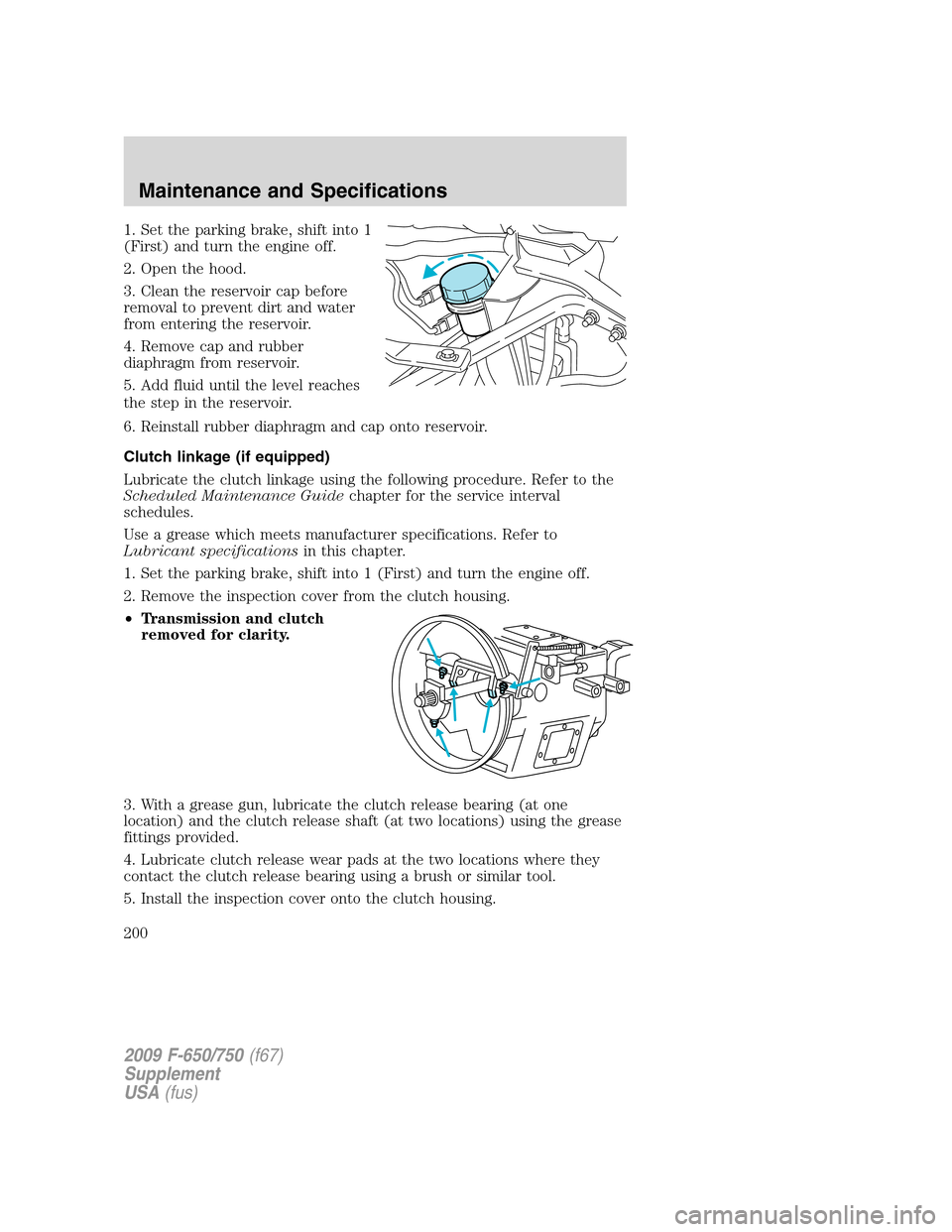
1. Set the parking brake, shift into 1
(First) and turn the engine off.
2. Open the hood.
3. Clean the reservoir cap before
removal to prevent dirt and water
from entering the reservoir.
4. Remove cap and rubber
diaphragm from reservoir.
5. Add fluid until the level reaches
the step in the reservoir.
6. Reinstall rubber diaphragm and cap onto reservoir.
Clutch linkage (if equipped)
Lubricate the clutch linkage using the following procedure. Refer to the
Scheduled Maintenance Guidechapter for the service interval
schedules.
Use a grease which meets manufacturer specifications. Refer to
Lubricant specificationsin this chapter.
1. Set the parking brake, shift into 1 (First) and turn the engine off.
2. Remove the inspection cover from the clutch housing.
•Transmission and clutch
removed for clarity.
3. With a grease gun, lubricate the clutch release bearing (at one
location) and the clutch release shaft (at two locations) using the grease
fittings provided.
4. Lubricate clutch release wear pads at the two locations where they
contact the clutch release bearing using a brush or similar tool.
5. Install the inspection cover onto the clutch housing.
2009 F-650/750(f67)
Supplement
USA(fus)
Maintenance and Specifications
200
Page 201 of 276
TRANSMISSION FLUID
Always dispose of used automotive fluids in a responsible manner.
Follow your community’s standards for disposing of these types of fluids.
Call your recycling center to find out about recycling automotive fluids.
Automatic transmission fluid
Refer to your Allison Automatic Transmission Operator’s Manual for
scheduled intervals for transmission fluid checks and changes. Your
transmission does not consume fluid. However, the fluid level should be
checked if the transmission is not working properly, i.e., if the
transmission slips or shifts slowly or if you notice some sign of fluid
leakage.
Automatic transmission fluid expands when warmed. To obtain an
accurate fluid check, drive the vehicle until it is warmed up
(approximately 20 miles [30 km]). If your vehicle has been operated for
an extended period at high speeds, in city traffic or during hot weather,
the vehicle should be turned off for about 30 minutes to allow fluid to
cool before checking.
1. Drive the vehicle 20 miles (30 km) or until it reaches normal operating
temperature.
2. Park the vehicle on a level surface and engage the parking brake.
3. With the parking brake engaged and your foot on the brake pedal,
start the engine and move the gearshift lever through all of the gear
ranges. Allow sufficient time for each gear to engage.
4. Place the gearshift lever in N (Neutral) or P (Park) and leave the
engine running.
5. Remove the dipstick, wiping it clean with a clean, dry lint free rag.
6. Install the dipstick making sure it is fully seated in the filler tube.
7. Remove the dipstick and inspect the fluid level.
If you must add transmission fluid, make sure the correct type of fluid is
being used. The type of fluid used is indicated in your Allison Automatic
Transmission Operator’s Manual.
Fluid levels above the safe range may result in transmission failure; an
overfill condition of transmission fluid may cause shift and/or
engagement concerns and/or possible damage.
Use of a non-approved automatic transmission fluid may cause
internal transmission component damage.
2009 F-650/750(f67)
Supplement
USA(fus)
Maintenance and Specifications
201