2009 FORD F750 fuel
[x] Cancel search: fuelPage 195 of 276

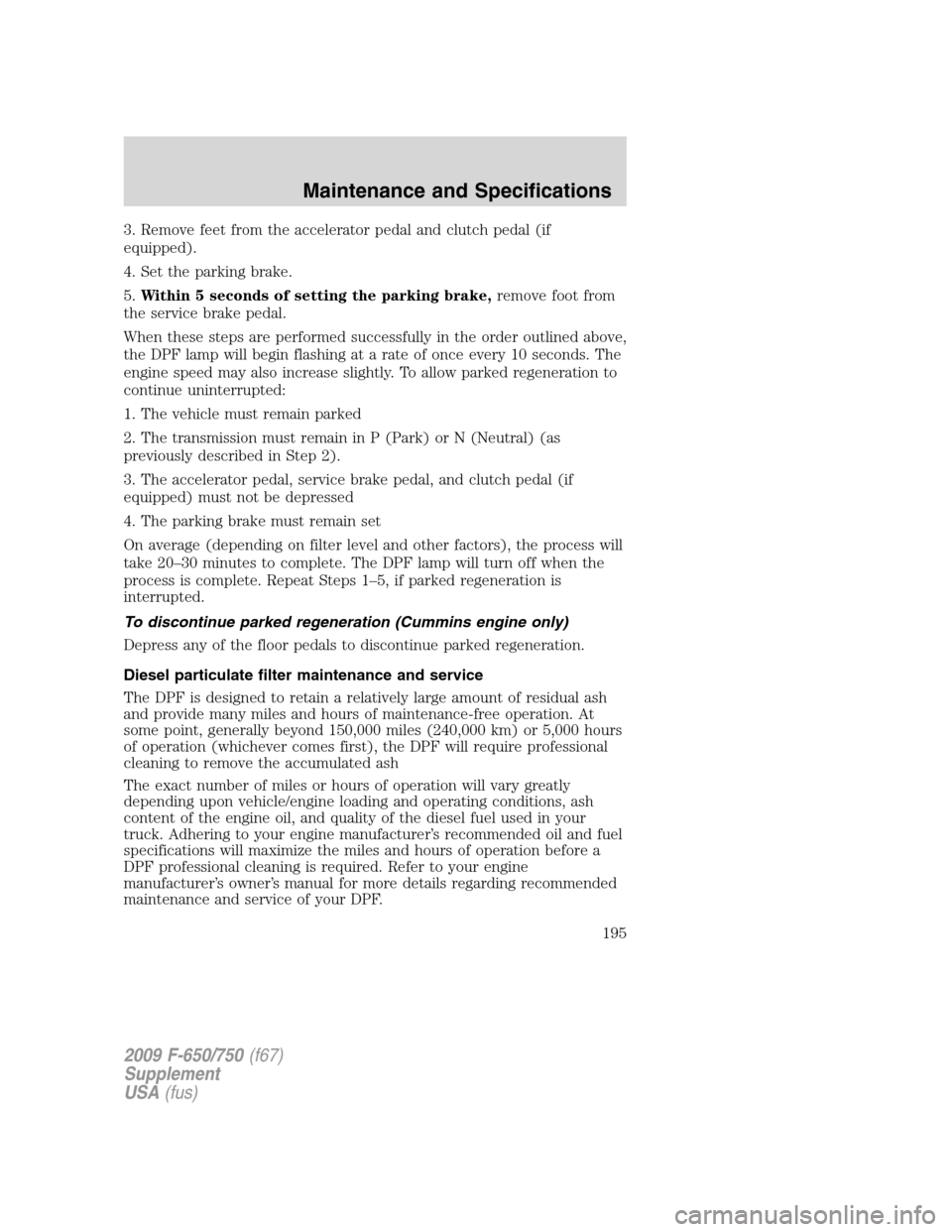
3. Remove feet from the accelerator pedal and clutch pedal (if
equipped).
4. Set the parking brake.
5.Within 5 seconds of setting the parking brake,remove foot from
the service brake pedal.
When these steps are performed successfully in the order outlined above,
the DPF lamp will begin flashing at a rate of once every 10 seconds. The
engine speed may also increase slightly. To allow parked regeneration to
continue uninterrupted:
1. The vehicle must remain parked
2. The transmission must remain in P (Park) or N (Neutral) (as
previously described in Step 2).
3. The accelerator pedal, service brake pedal, and clutch pedal (if
equipped) must not be depressed
4. The parking brake must remain set
On average (depending on filter level and other factors), the process will
take 20–30 minutes to complete. The DPF lamp will turn off when the
process is complete. Repeat Steps 1–5, if parked regeneration is
interrupted.
To discontinue parked regeneration (Cummins engine only)
Depress any of the floor pedals to discontinue parked regeneration.
Diesel particulate filter maintenance and service
The DPF is designed to retain a relatively large amount of residual ash
and provide many miles and hours of maintenance-free operation. At
some point, generally beyond 150,000 miles (240,000 km) or 5,000 hours
of operation (whichever comes first), the DPF will require professional
cleaning to remove the accumulated ash
The exact number of miles or hours of operation will vary greatly
depending upon vehicle/engine loading and operating conditions, ash
content of the engine oil, and quality of the diesel fuel used in your
truck. Adhering to your engine manufacturer’s recommended oil and fuel
specifications will maximize the miles and hours of operation before a
DPF professional cleaning is required. Refer to your engine
manufacturer’s owner’s manual for more details regarding recommended
maintenance and service of your DPF.
2009 F-650/750(f67)
Supplement
USA(fus)
Maintenance and Specifications
195
Page 203 of 276

7. Add enough fluid through the filler plug opening so that the fluid level
is up to the bottom of the opening.
8. Clean and install the filler plug securely.
CHASSIS-MOUNTED CHARGE AIR COOLER
Inspect charge air cooler daily
With the engine off, visually inspect the charge air cooler core assembly
for debris and clogging of external fins. Prior to engine operation,
remove any debris blocking the core.
•Turbocharger-to-charge air cooler
•Charge air cooler-to-intake manifold pipe
•Mounting bracket
•Chassis-mounted charge air cooler core
Inspect air intake piping
•Check for accumulation of salt deposits (where applicable). If present,
disassemble and clean the complete air intake piping system. If the
intake piping is pitted, use Motorcraft Silicone Gasket and Sealant
TA-30 to seal joints against leakage.
•Check for loose hoses and clamps.
•Check for ruptured or collapsed hoses.
•Check air cleaner housing for cracks.
ELECTRICAL SYSTEM INSPECTIONS
Periodically inspect electrical connectors on the outside of the cab, on
the engine and frame for corrosion and tightness. Exposed terminals
such as the fuel sender, cranking motor, alternator and feed-through
studs should be cleaned and re-coated with a lubricant sealing grease
such as Motorcraft Silicone Brake Caliper Grease and Dielectic
Compound XG-3, or equivalent. This should include the ground cable
connector for batteries, engine and cab as well as the jump starting stud.
Accessory feed connections
Vehicle electrical systems are complex and often include powertrain
components such as engine and transmission controls, instrument panels,
ABS, etc. While most systems operate on battery voltage (12 volts),
some systems can be as high as 90 volts or as low as five volts. Refer to
the Electrical Circuit Diagram Manuals, available from your vehicle’s
2009 F-650/750(f67)
Supplement
USA(fus)
Maintenance and Specifications
203
Page 216 of 276

Under-inflation is the primary cause of premature tire concerns including
sudden loss of air. In addition, low inflation causes an increase in rolling
resistance. This results in reduced fuel mileage, a loss in tread mileage,
and uneven wear due to increased tread movement. To determine proper
inflation refer to the tire manufacturer load/inflation guide which can be
found on the tire manufacturer website or at your local truck tire dealer.
Inspection
Check condition of tires for abnormal wear patterns, and proper inflation
pressures. Cut or broken tire casing must be repaired or replaced.
Tires should be inspected for the following conditions. If any are present,
the tire should be removed and repaired, retreaded or scrapped as the
condition indicates.
•Any blister, bump or raised portion anywhere on the surface of the
tire tread or sidewall (other than a bump made by a repair). These
indicate the start of internal separation.
•Any cut that reaches to the belt or ply cords, or any cut that is large
enough to grow in size and depth.
•Any nail or puncturing object.
•If any stone or object is held by a tread groove and is starting to drill
into the tread base, remove the object.
Proper tire inflation, toe-in adjustment, loads, and road speeds are
important factors governing tire mileage, steering ease and
maneuverability.
Loads
WARNING:Loading tires beyond their rated capacity decreases
tire life requiring more frequent replacement of tires.
Overloading creates an unsafe condition that may result in sudden air
loss from a tire failure resulting in an accident that could cause
property damage, personal injury or death.
Note:Your GAW/GVW rating is correct at the time of your vehicle
production, and reflects the exact rating of the tires specified. When
replacing tires be sure that the replacement tire load rating (listed in
pounds and kilograms on the tire sidewall) is the same or higher than
the tire that is removed. Failure to do so will adversely affect maximum
load carrying capacity. Tires with the same size specification do not
always have the same load specification.
2009 F-650/750(f67)
Supplement
USA(fus)
Maintenance and Specifications
216
Page 235 of 276

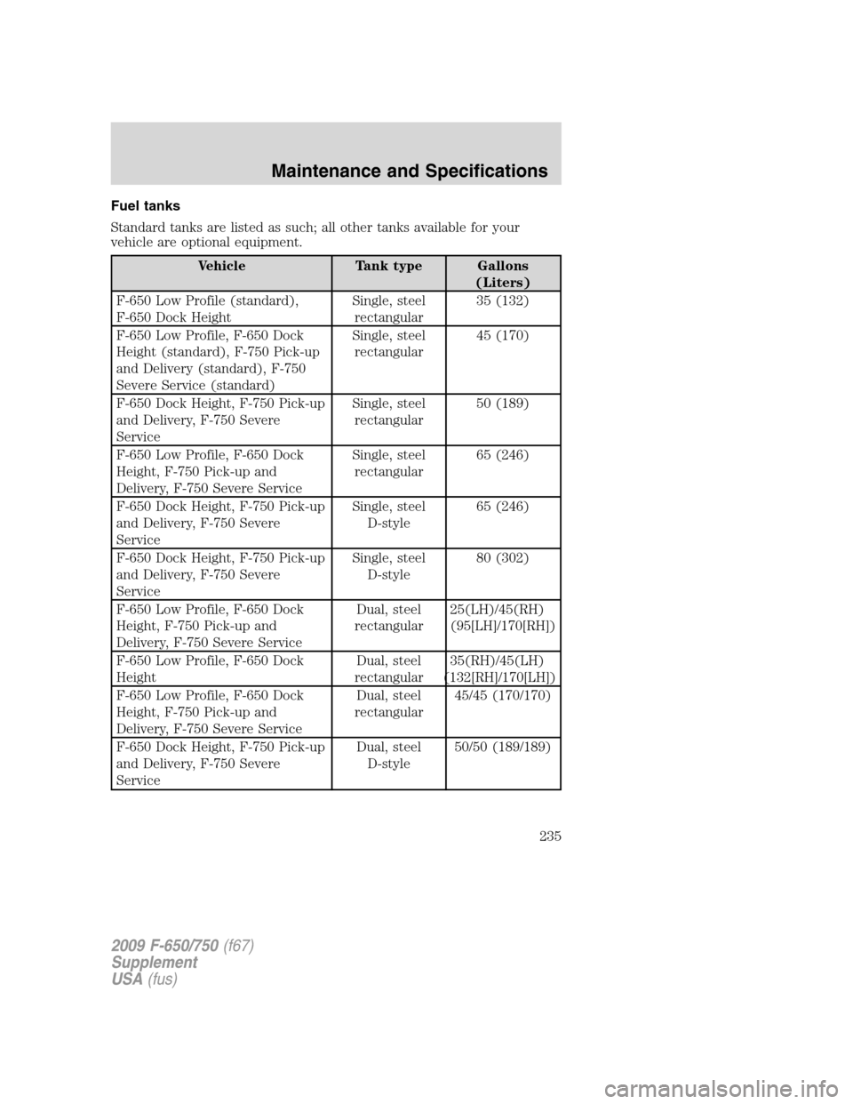
Fuel tanks
Standard tanks are listed as such; all other tanks available for your
vehicle are optional equipment.
Vehicle Tank type Gallons
(Liters)
F-650 Low Profile (standard),
F-650 Dock HeightSingle, steel
rectangular35 (132)
F-650 Low Profile, F-650 Dock
Height (standard), F-750 Pick-up
and Delivery (standard), F-750
Severe Service (standard)Single, steel
rectangular45 (170)
F-650 Dock Height, F-750 Pick-up
and Delivery, F-750 Severe
ServiceSingle, steel
rectangular50 (189)
F-650 Low Profile, F-650 Dock
Height, F-750 Pick-up and
Delivery, F-750 Severe ServiceSingle, steel
rectangular65 (246)
F-650 Dock Height, F-750 Pick-up
and Delivery, F-750 Severe
ServiceSingle, steel
D-style65 (246)
F-650 Dock Height, F-750 Pick-up
and Delivery, F-750 Severe
ServiceSingle, steel
D-style80 (302)
F-650 Low Profile, F-650 Dock
Height, F-750 Pick-up and
Delivery, F-750 Severe ServiceDual, steel
rectangular25(LH)/45(RH)
(95[LH]/170[RH])
F-650 Low Profile, F-650 Dock
HeightDual, steel
rectangular35(RH)/45(LH)
(132[RH]/170[LH])
F-650 Low Profile, F-650 Dock
Height, F-750 Pick-up and
Delivery, F-750 Severe ServiceDual, steel
rectangular45/45 (170/170)
F-650 Dock Height, F-750 Pick-up
and Delivery, F-750 Severe
ServiceDual, steel
D-style50/50 (189/189)
2009 F-650/750(f67)
Supplement
USA(fus)
Maintenance and Specifications
235
Page 237 of 276

GENERAL MAINTENANCE INFORMATION
The general maintenance services listed in this section are required
because they are considered essential to the life and performance of
your vehicle. Refer to the “Daily Owner Checks” chart for important
maintenance items.
Ford Motor Company recommends you perform the owner maintenance
services listed in this section. These services are matters of day-to-day
care that are important to the proper operation of your vehicle. In
addition to the conditions described in owner maintenance, be alert for
any unusual noise, vibration or other indication that your vehicle may
need service and attend to it promptly.
Your vehicle is very sophisticated and built with multiple complex
performance systems. Every manufacturer develops these systems using
different specifications and performance features. That’s why it’s
important to rely upon your Ford dealership to properly diagnose and
repair your vehicle.
Use only recommended fuels, lubricants, fluids and service parts
conforming to Ford specifications. Motorcraft parts are designed and
built for best performance in your vehicle. Using these parts for
replacement is your assurance that Ford-Built quality stays in your
vehicle.
Non-Ford approved chemicals or additives are not required for factory
recommended maintenance. In fact, Ford Motor Company recommends
against the use of such additive products unless specifically
recommended by Ford for a particular application.
SCHEDULED MAINTENANCE
Ford Motor Company has recommended maintenance intervals for
various parts and component systems based upon engineering testing.
Ford Motor Company relies upon this testing to determine the most
appropriate mileage for replacement of oils and fluids to protect your
vehicle at the lowest overall cost to you and recommends against
maintenance schedules that deviate from the scheduled maintenance
information.
The maintenance or replacement of the emission control devices (or
systems) in your new Ford Motor Company vehicle (or engine) may be
performed at your expense. These services may be performed by any
automotive repair establishment or individual using automotive parts
equivalent to those with which your vehicle or engine was originally
equipped. If any parts other than Ford, Motorcraft, or Ford authorized,
2009 F-650/750(f67)
Supplement
USA(fus)
Scheduled Maintenance Guide
237
Page 239 of 276

FACTORY AUTHORIZED SYSTEMS CHECKS
In the event that your vehicle experiences a component related concern,
please contact your Ford dealership. The Ford Motor Company Trained
Technicians who work at Ford dealerships are specifically trained to
understand your vehicle.
A proper repair begins with a thorough system check. A Factory
Authorized Systems Check can ONLY be found at a Ford dealership. In
some circumstances, the technician may need to request your
authorization to perform additional operations to determine the final
diagnosis. The technician’s goal is to ensure that your vehicle is fixed
right the first time, at the best value to you.
The following list represents several of the Factory Authorized Systems
Checks available at a participating Ford dealers:
•Air Conditioning
•Check Engine Light
•All Wheel Drive and 4x4
•Automatic Transmission
•Engine Cooling and Cabin Heating
•Steering and Suspension
•Charge/Start/Battery
•Wheel Alignment
•Anti-Lock Brake System
EMISSIONS CONTROL SYSTEM
To ensure the emissions control systems operate effectively, you should
have the services listed in the maintenance schedule performed at the
specified time and mileage/km intervals. You should avoid running out of
fuel or turning off the ignition while the vehicle is in motion, especially
at high speeds.
WARNING:Because of high engine compartment and exhaust
system temperatures resulting from emissions equipment, do not
park, idle or operate your vehicle in dry grass or other dry ground
cover where the possibility of ground fire exists.
Do not make unauthorized modifications to the engine or vehicle.
Modifications causing increased amounts of unburned fuel to reach the
exhaust system can significantly increase the temperature of the engine
compartment and/or the exhaust system.
2009 F-650/750(f67)
Supplement
USA(fus)
Scheduled Maintenance Guide
239
Page 240 of 276

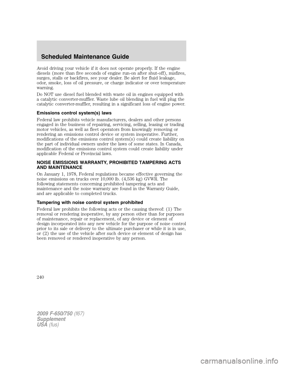
Avoid driving your vehicle if it does not operate properly. If the engine
diesels (more than five seconds of engine run-on after shut-off), misfires,
surges, stalls or backfires, see your dealer. Be alert for fluid leakage,
odor, smoke, loss of oil pressure, or charge indicator or over temperature
warning.
Do NOT use diesel fuel blended with waste oil in engines equipped with
a catalytic converter-muffler. Waste lube oil blending in fuel will plug the
catalytic converter-muffler, resulting in a significant loss of engine power.
Emissions control system(s) laws
Federal law prohibits vehicle manufacturers, dealers and other persons
engaged in the business of repairing, servicing, selling, leasing or trading
motor vehicles, as well as fleet operators from knowingly removing or
rendering an emissions control device or system inoperative. Further,
modifications of the emissions control system(s) could create liability on
the part of individual owners under the laws of some states. In Canada,
modification of the emissions control system could create liability under
applicable Federal or Provincial laws.
NOISE EMISSIONS WARRANTY, PROHIBITED TAMPERING ACTS
AND MAINTENANCE
On January 1, 1978, Federal regulations became effective governing the
noise emissions on trucks over 10,000 lb. (4,536 kg) GVWR. The
following statements concerning prohibited tampering acts and
maintenance and the noise warranty are found in the Warranty Guide,
and are applicable to completed trucks.
Tampering with noise control system prohibited
Federal law prohibits the following acts or the causing thereof: (1) The
removal or rendering inoperative, by any person other than for purposes
of maintenance, repair or replacement, of any device or element of
design incorporated into any new vehicle for the purpose of noise control
prior to its sale or delivery to the ultimate purchaser or while it is in use,
or (2) the use of the vehicle after such device or element of design has
been removed or rendered inoperative by any person.
2009 F-650/750(f67)
Supplement
USA(fus)
Scheduled Maintenance Guide
240
Page 246 of 276

Check every oil change
Engine systemCheck the engine cooling system -
hoses, clamps and protection*.
Inspect the drive belts.
Exhaust systemInspect the entire exhaust system
(including the inlet pipe(s),
muffler(s), outlet pipe(s), clamps and
fasteners) for holes, leakage,
breakage, corrosive damage and
separation from other components.
Adjust, service or replace with the
same or the equivalent part. (Also a
noise emission control service).
Suspension systemTighten the front and rear spring
U-bolts to the specified torque.
Driveline and rear axle
systemLubricate the U-joints and the slip
yoke.
Brake systemLube the air brake foot control valve,
hinge and roller.
Inspect the drum brake linings
through the inspection holes.
Lubricate the brake camshafts (air
brakes only).
Lubricate the brake slack adjuster (air
brakes only).
Lubricate rear caliper slide rails.
Inspect the disc brake pads and the
piston boots (hydraulic brakes only).
Clutch systemLubricate the clutch release cross
shaft and all linkages.
Check the clutch fluid.
Fuel systemDrain the accumulated water or
sediment from the fuel tank(s).
2009 F-650/750(f67)
Supplement
USA(fus)
Scheduled Maintenance Guide
246