2009 FORD F750 fuel
[x] Cancel search: fuelPage 95 of 276

Note:Idling in cold weather will not heat the engine to its normal
operating temperature. Long periods of idling in cold weather can cause
a build-up of heavy deposits of carbon and rust on valve stems causing
them to stick which, in turn, can cause valvetrain damage.
Winter fronts
The use of winter fronts, or other air-restrictive devices mounted in front
of the radiator on vehicles with chassis-mounted charge air coolers, are
not recommended unless extremely cold weather conditions exist. Air
flow restriction can cause high exhaust temperatures, power loss,
excessive fan usage and a reduction in fuel economy. If you must use a
winter front, the device should have a permanent opening of at least 120
sq in. (774 sq. cm) directly in line with the fan hub.
Hot weather operation
•Keep the engine cooling system filled with a clean, permanent coolant
solution to protect against damage from overheating.
•Fill the fuel tank at the end of daily operation to prevent condensation
in the fuel system.
•Keep external surfaces of the engine, radiator, charge air cooler, A/C
condenser and accessories clean to avoid dirt build-up.
Above normal coolant temperatures could be experienced while driving
in a transmission gear ratio which lugs the engine. To correct this
problem, engine speed should be increased by downshifting in to the
next lower gear to increase engine RPM.
Starting a turbocharged engine with the vehicle on a steep grade
When starting a diesel engine when the loaded vehicle is on a grade, the
engine RPM will start to fall slightly when the clutch is engaged; do not
disengage the clutch and try to increase engine RPM as this may damage
driveline components. The engine will recover as the vehicle begins
moving.
Engine shutdown
Allow the engine to idle for three to five minutes before shutting it
down. The larger the engine, the greater the need for this idling period.
However, do not let the engine idle for more than 10 minutes.
Restarting after running out of fuel
The fuel system may need to be purged of air, refer toRunning out of
fuelin theMaintenance and Specificationschapter.
2009 F-650/750(f67)
Supplement
USA(fus)
Driving
95
Page 96 of 276

GENERAL OPERATING INSTRUCTIONS
•Avoid extended (more than 10 minutes) and unnecessary idling.
•Start the vehicle in motion by using the highest gear speed in the
transmission that will let the engine easily start the load without
slipping the clutch.
•Accelerate smoothly and evenly; rapid acceleration increases fuel
consumption without increasing engine performance.
•When approaching a hill, depress the accelerator smoothly to start the
incline at full power, then shift down as needed to maintain vehicle
speed.
•When going down a hill, or long steep grades, prevent over-speeding
of the engine. The engine governor has no control over engine speed
when it is being pushed by a loaded vehicle.
•Always shift to a lower gear at high altitudes to prevent engine
smoking.
•Operate in a gear that will permit an engine speed not in excess of the
maximum governed speed or high-idle RPM (no load).
•Normally, choose the same gear to descend the hill that you would use
to ascend the hill.
WARNING:All vehicles have blind spots. To reduce the risk of
severe injury or property damage, never move your vehicle to
the side or rear or change lanes without being sure your way is clear
on both sides and to your rear.
Backing up
WARNING:To reduce the risk of the possibility of personal
injury while backing the vehicle, always be sure your vehicle’s
path is clear.
Before backing your vehicle, be sure you can do so safely. If anything
behind the cab limits your view, do not rely on mirrors alone to ensure
that your intended path is clear. If other people are in the vicinity, have
someone standing well behind your vehicle and outside of your intended
path (visible through an exterior mirror) guide you as you back up.
2009 F-650/750(f67)
Supplement
USA(fus)
Driving
96
Page 102 of 276

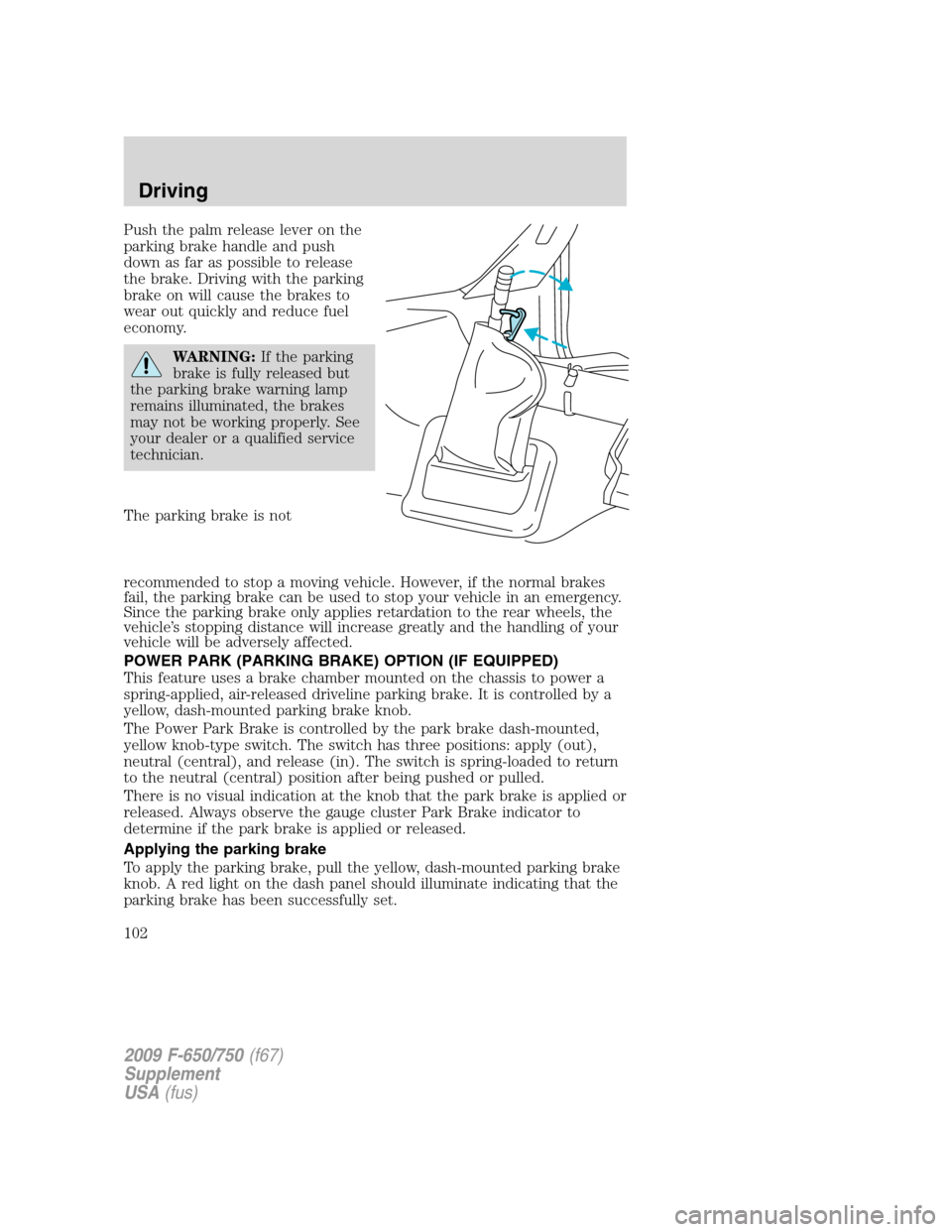
Push the palm release lever on the
parking brake handle and push
down as far as possible to release
the brake. Driving with the parking
brake on will cause the brakes to
wear out quickly and reduce fuel
economy.
WARNING:If the parking
brake is fully released but
the parking brake warning lamp
remains illuminated, the brakes
may not be working properly. See
your dealer or a qualified service
technician.
The parking brake is not
recommended to stop a moving vehicle. However, if the normal brakes
fail, the parking brake can be used to stop your vehicle in an emergency.
Since the parking brake only applies retardation to the rear wheels, the
vehicle’s stopping distance will increase greatly and the handling of your
vehicle will be adversely affected.
POWER PARK (PARKING BRAKE) OPTION (IF EQUIPPED)
This feature uses a brake chamber mounted on the chassis to power a
spring-applied, air-released driveline parking brake. It is controlled by a
yellow, dash-mounted parking brake knob.
The Power Park Brake is controlled by the park brake dash-mounted,
yellow knob-type switch. The switch has three positions: apply (out),
neutral (central), and release (in). The switch is spring-loaded to return
to the neutral (central) position after being pushed or pulled.
There is no visual indication at the knob that the park brake is applied or
released. Always observe the gauge cluster Park Brake indicator to
determine if the park brake is applied or released.
Applying the parking brake
To apply the parking brake, pull the yellow, dash-mounted parking brake
knob. A red light on the dash panel should illuminate indicating that the
parking brake has been successfully set.
2009 F-650/750(f67)
Supplement
USA(fus)
Driving
102
Page 134 of 276

Note:Never use the differential lock at vehicle speeds above 25 mph
(40 km/h).
The differential lock and differential lock light will automatically
disengage at speeds above 25 mph (40 km/h). The differential lock will
remain off until either the vehicle is restarted or the differential lock
switch is turned off then back on.
Axle conversions
It is not recommended, or approved, for axle conversions to be
performed. However, it is understood that, on occasion, aftermarket
add-on axles are installed by others on the truck chassis which allow
operator control for weight transfer from other axles (i.e., air lift axles).
WARNING:When operating a loaded vehicle, the driver must
keep all adjustable axles on the ground at all times, supporting
their share of the vehicle’s load. Failure to do so can overload other
axles, tires, wheels, springs, steering components, brakes and frames,
resulting in early component failure, loss of vehicle control, possible
property damage and personal injury.
TWO-SPEED REAR AXLE (IF EQUIPPED)
A two-speed rear axle allows the driver to select a LO range for greater
pulling power and a HI range for greater road speed and fuel economy.
These ranges can also be used to provide additional steps between
transmission shifts when driving on steep grades and/or fuel economy
may be factors.
Note:Do not shift between ranges when the speed control is on.
WARNING:Never shift a two-speed axle when descending a
steep grade as this may cause loss of vehicle control and result
in personal injury.
Axle shifting
Manual transmissions:
•To downshift,select the next lower gear, release and depress the
accelerator pedal rapidly, or while holding the accelerator pedal down,
release and engage the clutch rapidly.Note:The clutch method is
recommended when driving at slower speeds.
•To upshift,keep the accelerator pedal down, select the next higher
gear, release the accelerator and pause until the axle upshifts.Note:
De-clutch for smoother axle upshifts when driving at slower speeds.
2009 F-650/750(f67)
Supplement
USA(fus)
Driving
134
Page 146 of 276

Fuse/Relay
LocationFuse Amp
RatingFuse Description
15 10A Interior lamp relay, GEM, Vanity mirrors
16 15A High beams, Indicator
17 — Not used
18 5A Headlamp switch interior lighting
19 15A Engine control
20 5A Starting system
21 10A DRL resistor
22 15A Air horn, Air suspension dump, Two-speed
axle, Driver-controlled locking differential
23 10A Flasher
24 15A ABS, Air dryer, Vacuum pump, Fuel heater
relay
25 10A Function selector switch
26 10A RH low beam headlamp
27 — Not used
28 10A LH low beam headlamp
29 10A Cluster warning lamps, Gauges, GEM,
Hydraulic ABS
30 15A Allison electronic transmission
31 — Not used
Relay 1 — Interior lamps
Relay 2 — Not used
Relay 3 — Horn
Relay 4 — One-touch down window
Relay 5 — Not used
Power distribution box
WARNING:Always disconnect the battery before servicing high
current fuses.
2009 F-650/750(f67)
Supplement
USA(fus)
Roadside Emergencies
146
Page 147 of 276

WARNING:To reduce risk of electrical shock, always replace
the cover to the Power Distribution Box before reconnecting the
battery or refilling fluid reservoirs.
Fuse/Relay
LocationFuse Amp
RatingFuse Description
1 15A* Main light switch
2 30A* Power seat (driver)
3 30A* Power seat (passenger)
4 15A* Washer pump relay, Washer pump motor
5 5A* Full power brake switch
6 15A* Air intake heater (Caterpillar engine only)
7 15A* Stoplamp switches (Air brake vehicles only)
8 25A* Fuel heater relay (Caterpillar
engine-equipped vehicles with dual fuel tanks
only)
9 20A* Inhibit relay, Engine ECM, Cluster,
Transmission TCM
10 15A* Heated drain valve
11 30A* Electric trailer brake
2009 F-650/750(f67)
Supplement
USA(fus)
Roadside Emergencies
147
Page 148 of 276

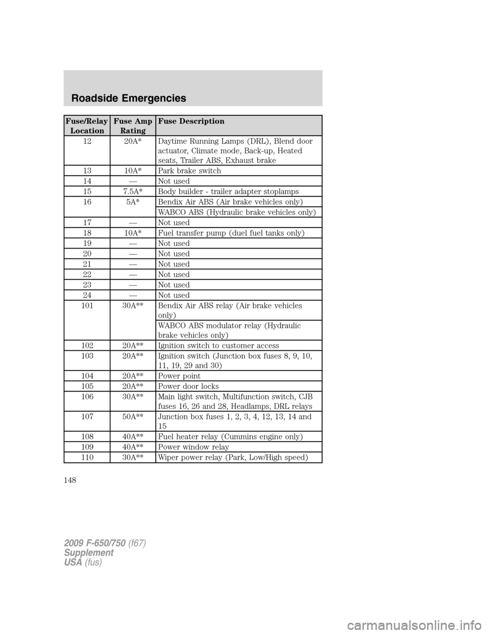
Fuse/Relay
LocationFuse Amp
RatingFuse Description
12 20A* Daytime Running Lamps (DRL), Blend door
actuator, Climate mode, Back-up, Heated
seats, Trailer ABS, Exhaust brake
13 10A* Park brake switch
14 — Not used
15 7.5A* Body builder - trailer adapter stoplamps
16 5A* Bendix Air ABS (Air brake vehicles only)
WABCO ABS (Hydraulic brake vehicles only)
17 — Not used
18 10A* Fuel transfer pump (duel fuel tanks only)
19 — Not used
20 — Not used
21 — Not used
22 — Not used
23 — Not used
24 — Not used
101 30A** Bendix Air ABS relay (Air brake vehicles
only)
WABCO ABS modulator relay (Hydraulic
brake vehicles only)
102 20A** Ignition switch to customer access
103 20A** Ignition switch (Junction box fuses 8, 9, 10,
11, 19, 29 and 30)
104 20A** Power point
105 20A** Power door locks
106 30A** Main light switch, Multifunction switch, CJB
fuses 16, 26 and 28, Headlamps, DRL relays
107 50A** Junction box fuses 1, 2, 3, 4, 12, 13, 14 and
15
108 40A** Fuel heater relay (Cummins engine only)
109 40A** Power window relay
110 30A** Wiper power relay (Park, Low/High speed)
2009 F-650/750(f67)
Supplement
USA(fus)
Roadside Emergencies
148
Page 149 of 276

Fuse/Relay
LocationFuse Amp
RatingFuse Description
111 30A** Park lamps relay, Park lamps
112 40A** Blower motor relay, Blower motor
113 30A** Heated seats, Air ride seat
114 25A** Hydraulic ABS ECU power
115 20A** Ignition switch, Central Junction Box fuses 8,
9, 10 and 11, Starter motor relay
116 30A** Left/Right turn relays, Back-up lamp relay
117 20A** Stoplamps relay
118 60A** Hydraulic brake vehicles (Trailer tow package
only)
119/120 60A** Hydraulic brake vehicle (Trailer tow package
only)
Air brake vehicles (Trailer tow package only)
121/122 60A** Hydraulic brake, ABS system
Air brake trailer tow fuse block
201 — Washer pump relay
202 — Wiper speed relay
203 — Wiper on/off relay
204 — Wiper power relay
205 — RH stop/turn relay
206 — LH stop/turn relay
207 — Hydraulic ABS event relay
208 — Back-up lamps relay
209 — Stoplamp relay
301 — Fuel heater/Fuel transfer pump relay
302 — Park lamps relay
303 — Blower motor relay
304 — Not used
* Mini fuse **Maxi fuse
2009 F-650/750(f67)
Supplement
USA(fus)
Roadside Emergencies
149