2009 FORD F750 Brake reservoir
[x] Cancel search: Brake reservoirPage 11 of 276

To be sure your vehicle is ready to operate, conduct a pre-trip inspection
at the beginning of each work period. Follow the steps listed in this
section to ensure a proper vehicle inspection procedure. The pages in
this section may be produced locally and used on a regular basis.
VEHICLE INSPECTION INFORMATION
Note:Always make sure the parking brake is applied before starting the
engine.
Engine compartment (with engine stopped)
Engine oil level:Use the engine oil dipstick to verify that the
engine oil level is between the ADD and
OPERATING RANGE marks.
Engine coolant
level:Look through the plastic reservoir or the clear
sight glass on the reservoir, depending upon
vehicle equipment, and make sure the fluid is
within the minimum and maximum fluid level
range as marked on the reservoir.Do not
remove pressure cap until the coolant has
cooled.
Power steering fluid:Verify that the fluid level is in the proper
operating range. Refer toPower steering
fluidin theMaintenance and Specifications
chapter.
Brake fluid (master
cylinder):Remove the master cylinder caps and inspect
the fluid level. The full mark is at the bottom
of the opening of the fluid ports.
Hydraulic clutch
fluid:Check for adequate amount of hydraulic clutch
fluid. Fluid level should be at the step of the
reservoir; refer toClutch fluid/linkage
adjustmentsin theMaintenance and
Specificationschapter.
Belts (Fan,
alternator, water
pump and A/C
compressor):Check for glazing, fraying or cracking. There
should be no more than five - seven cracks per
rib per inch (2.5 cm).
2009 F-650/750(f67)
Supplement
USA(fus)
Vehicle Inspection Guide
11
Page 108 of 276

Air brake reservoir draining
WARNING:Failure to drain air brake reservoirs can result in a
reduction or loss of braking ability due to fluid accumulation in
the reservoir and/or possible freeze-up during cold weather.
Drain all the air brake reservoirs
daily, completely to 0 psi/kPa, by
opening the draincock at the ends
of the tanks (where accessible.
Pull-chains are used when the
drains are undercab or otherwise
inaccessible). Close draincock after
complete draining. Air tanks
equipped with automatic moisture
ejector valves may also be drained
manually as required to maintain a
dry air system. Contact your dealer if you are unsure of the air reservoir
locations or the draining procedure.
Parking brake
WARNING:Do not use the gearshift selector in place of the
parking brake; unexpected and possible sudden vehicle
movement may occur if these precautions are not taken. Always set
the parking brake fully AND make sure the gearshift selector is in R
(Reverse) for vehicles equipped with manual transmission, N (Neutral)
for vehicles with automatic transmission (except Allison 2200
transmission) or P (Park) (Allison 2200 transmission).
If the service brakes should fail to operate while the vehicle is in motion,
you can make an emergency stop with the parking brake. Since the
parking brake only applies stopping power to the rear wheels, the
vehicle’s stopping distance will greatly increase and the handling of the
vehicle will be adversely affected. Repairs should be made immediately
to an inoperative air brake system circuit.
2009 F-650/750(f67)
Supplement
USA(fus)
Driving
108
Page 125 of 276

Allison 3000 series push-button shifter
To shift the transmission into R
(Reverse) or D (Drive), depress the
brake pedal, then press R or D, then
release the brake pedal. To select a
lower range when in D (Drive),
press the down-arrow button. To
select a higher range when in D
(Drive), press the up-arrow button.
To place the transmission in N
(Neutral), press N.
Automatic transmission fluid operating temperatures
Allison 2200/2500 – The sump/fluid reservoir temperatures should not
exceed 250°F (120°C). The converter temperature should not exceed
300°F (144°C).
Eaton UltraShift transmission (if equipped)
The Eaton UltraShift is a transmission that can automatically select and
engage the proper transmission gears. Vehicles equipped with this
transmission do not have a clutch pedal. For operating instructions refer
to theEaton UltraShift Driver Instructions manual.
Eaton UltraShift push-button shifter
For operation of the push-button
shifter, refer to theOperation —
Shift Console Positionssection of
theEaton UltraShift Driver
Instructions manual.
2009 F-650/750(f67)
Supplement
USA(fus)
Driving
125
Page 147 of 276

WARNING:To reduce risk of electrical shock, always replace
the cover to the Power Distribution Box before reconnecting the
battery or refilling fluid reservoirs.
Fuse/Relay
LocationFuse Amp
RatingFuse Description
1 15A* Main light switch
2 30A* Power seat (driver)
3 30A* Power seat (passenger)
4 15A* Washer pump relay, Washer pump motor
5 5A* Full power brake switch
6 15A* Air intake heater (Caterpillar engine only)
7 15A* Stoplamp switches (Air brake vehicles only)
8 25A* Fuel heater relay (Caterpillar
engine-equipped vehicles with dual fuel tanks
only)
9 20A* Inhibit relay, Engine ECM, Cluster,
Transmission TCM
10 15A* Heated drain valve
11 30A* Electric trailer brake
2009 F-650/750(f67)
Supplement
USA(fus)
Roadside Emergencies
147
Page 176 of 276

Air brakes - air dryer
Performance of desiccant or after-cooler type air dryers is dependent on
climatic conditions in which your vehicle is operating. Maintenance
schedules must be established for each specific operation.
The use of an air dryer on a vehicle does not eliminate the need to
periodically drain the air reservoirs.
Air brakes - desiccant air dryer
Inspect for moisture in the air system by opening reservoirs, drain cocks
or valves and checking for presence of water. The presence of small
amounts of water due to condensation is normal and should not be
considered as an indication that the dryer is not functioning properly.
The desiccant cartridge should be replaced or rebuilt when it has been
determined that the desiccant is contaminated and does not have
adequate water absorption capacity. The desiccant change interval may
vary; it is generally recommended that the desiccant be replaced every
12 months (yearly). If experience has shown that extended or shortened
life has resulted for a particular installation, then the yearly interval can
be increased or decreased accordingly.
Hydraulic brakes - inspection and adjustment
A regular schedule for periodic cleaning, lubrication, adjustment and
inspection should be established based on the type of vehicle operation.
It is difficult to predetermine an exact maintenance interval (time or
mileage), since vehicles will be used in a wide variety of applications and
conditions. If you are uncertain of the proper schedule and procedures
for your vehicle, contact your dealer.
Inspect the brake lining every maintenance interval. Establish inspection
intervals that provide for lining replacement before damage to the disc
occurs. Excessive lining wear may expose the backing plate to the disc
causing scoring of the disc faces.
This inspection should be performed by a qualified technician and must
be in accordance with instructions provided by the service manual.
Note:Hydraulic brake system are power assisted. Braking capabilities
will be greatly reduced without engine assist.
Hydraulic brakes - fluid level
Fluid level should be at the bottom edge of the ring on each reservoir fill
port. Do not fill the master cylinder to the top of the reservoir.
2009 F-650/750(f67)
Supplement
USA(fus)
Maintenance and Specifications
176
Page 197 of 276

•The fan ratio should not be changed and the fan spacer dimensions
and positions should not be altered.
•Inspect the fan clutch for proper operation, make sure that the fan is
disengaged when cooling of the engine is not required.
•Check for proper operation of radiator shutters, if equipped. The
shutters should be open during normal operating temperatures.
Engine and Driveline System
•Transmission Enclosure:inspect for cracks, holes, and tears. Clean
any deposits such as oil, dirt, and stones.
•Engine valve covers and block covers are made to damp out engine
mechanical noise and, if needed, should be replaced with
recommended parts. Check for mechanical isolations.
Exhaust System
•Inspect the exhaust system for leaks at various joint connections and
tighten the clamps.
•Do a visual inspection for cracks or holes in the muffler and tail pipe.
•Always use the recommended parts when items need to be replaced.
•The tail pipe elbow or offset tail pipe orientation must not be changed
from the standard position as originally received.
•To avoid abnormal changes in vehicle sound levels, it is necessary for
the owner to perform inspections and necessary maintenance at the
intervals shown in theScheduled Maintenance Guidechapter.
POWER STEERING FLUID
Check the power steering fluid level using the following procedure. If
adding fluid is necessary, refer toLubricant Specificationsin this
chapter for the proper fluid type. Refer to theScheduled Maintenance
Guidechapter for the recommended service intervals.
1. Set the parking brake, shift into N (Neutral) (automatic transmission)
or 1 (First) (manual transmission) and turn the engine off.
2. Open the hood.
3. Clean the top of the power steering fluid reservoir.
4. Remove the dipstick from the reservoir and wipe the dipstick clean.
5. Reinstall the dipstick. Remove it again and check the fluid level.
2009 F-650/750(f67)
Supplement
USA(fus)
Maintenance and Specifications
197
Page 198 of 276

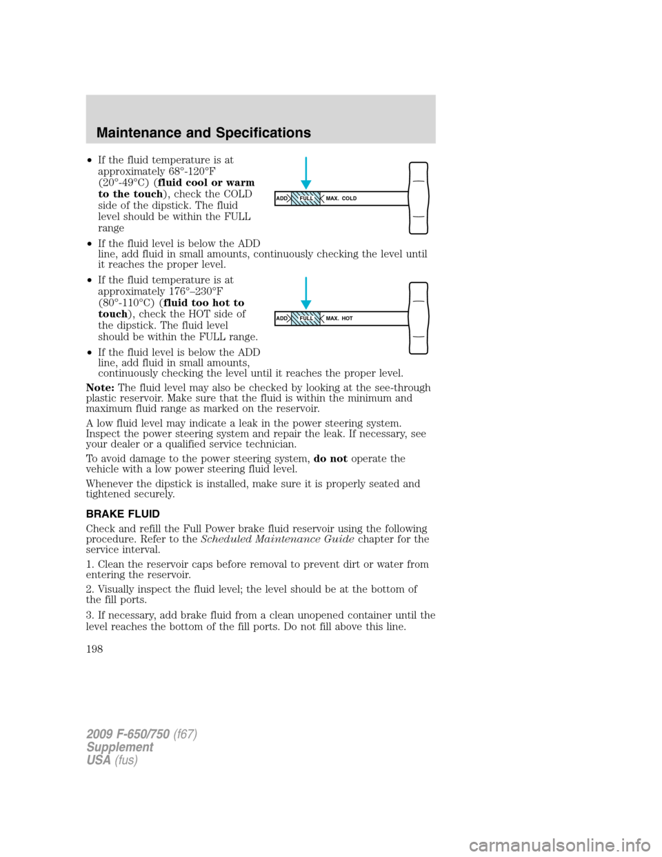
•If the fluid temperature is at
approximately 68°-120°F
(20°-49°C) (fluid cool or warm
to the touch), check the COLD
side of the dipstick. The fluid
level should be within the FULL
range
•If the fluid level is below the ADD
line, add fluid in small amounts, continuously checking the level until
it reaches the proper level.
•If the fluid temperature is at
approximately 176°–230°F
(80°-110°C) (fluid too hot to
touch), check the HOT side of
the dipstick. The fluid level
should be within the FULL range.
•If the fluid level is below the ADD
line, add fluid in small amounts,
continuously checking the level until it reaches the proper level.
Note:The fluid level may also be checked by looking at the see-through
plastic reservoir. Make sure that the fluid is within the minimum and
maximum fluid range as marked on the reservoir.
A low fluid level may indicate a leak in the power steering system.
Inspect the power steering system and repair the leak. If necessary, see
your dealer or a qualified service technician.
To avoid damage to the power steering system,do notoperate the
vehicle with a low power steering fluid level.
Whenever the dipstick is installed, make sure it is properly seated and
tightened securely.
BRAKE FLUID
Check and refill the Full Power brake fluid reservoir using the following
procedure. Refer to theScheduled Maintenance Guidechapter for the
service interval.
1. Clean the reservoir caps before removal to prevent dirt or water from
entering the reservoir.
2. Visually inspect the fluid level; the level should be at the bottom of
the fill ports.
3. If necessary, add brake fluid from a clean unopened container until the
level reaches the bottom of the fill ports. Do not fill above this line.
ADD MAX. COLDFULL
ADD MAX. HOTFULL
2009 F-650/750(f67)
Supplement
USA(fus)
Maintenance and Specifications
198
Page 199 of 276

4. Use only a DOT 3 brake fluid certified to meet manufacturer
specifications. Refer toLubricant specificationsin this chapter.
WARNING:Brake fluid is toxic. If brake fluid contacts the eyes,
flush eyes with running water for 15 minutes. Seek medical
attention if irritation persists. If taken internally, drink water and
induce vomiting. Seek medical attention immediately.
WARNING:If you use a brake fluid that is not DOT 3, you will
cause permanent damage to your brakes.
WARNING:Do not let the reservoir for the master cylinder run
dry. This may cause the brakes to fail.
CLUTCH FLUID/LINKAGE ADJUSTMENTS
Clutch fluid (if equipped)
Check the clutch fluid level. Refer to theScheduled Maintenance
Guidechapter for the service interval schedules.
During normal operation, the fluid level in the clutch reservoir should
remain constant. If the fluid level drops, maintain the fluid level at the
step in the reservoir.
Use only a DOT 3 brake fluid designed to meet manufacturer
specifications. Refer toLubricant specificationsin this chapter.
WARNING:Carefully read cautionary information on product
label. For MEDICAL EMERGENCY INFORMATION, contact a
physician or Poison Control Center immediately; on Ford-Motorcraft
products call: 1-800-959-3673 (FORD). Failure to follow these
instructions may result in personal injury.
2009 F-650/750(f67)
Supplement
USA(fus)
Maintenance and Specifications
199