2009 FORD F350 brakes
[x] Cancel search: brakesPage 2 of 419

Locks and Security 155
Keys 155
Locks 155
Anti-theft system 168
Seating and Safety Restraints 172
Seating 172
Safety restraints 181
Airbags 193
Child restraints 202
Tires, Wheels and Loading 225
Tire information 227
Tire inflation 230
Tire Pressure Monitoring System (TPMS) 245
Vehicle loading 256
Trailer towing 262
Trailer brake controller-integrated 267
Recreational towing 274
Driving 275
Starting 275
Brakes 280
Traction Control™ 282
Transmission operation 285
Reverse sensing system 292
Reverse camera 294
Roadside Emergencies 315
Getting roadside assistance 315
Hazard flasher control 316
Fuel pump shut-off switch 317
Fuses and relays 318
Changing tires 327
Wheel lug nut torque 342
Jump starting 343
Wrecker towing 348
Table of Contents
2
2009 F-250/350/450/550(f23)
Owners Guide, 3rd Printing
USA(fus)
ProCarManuals.com
Page 117 of 419
Note:
•Vehicle speed may vary momentarily when driving up and down a
steep hill.
•If the vehicle speed increases above the set speed on a downhill, you
may want to apply the brakes to reduce the speed.
•If the vehicle speed decreases more than 10 mph (16 km/h) below
your set speed on an uphill, your speed control will disengage.
Resuming a set speed
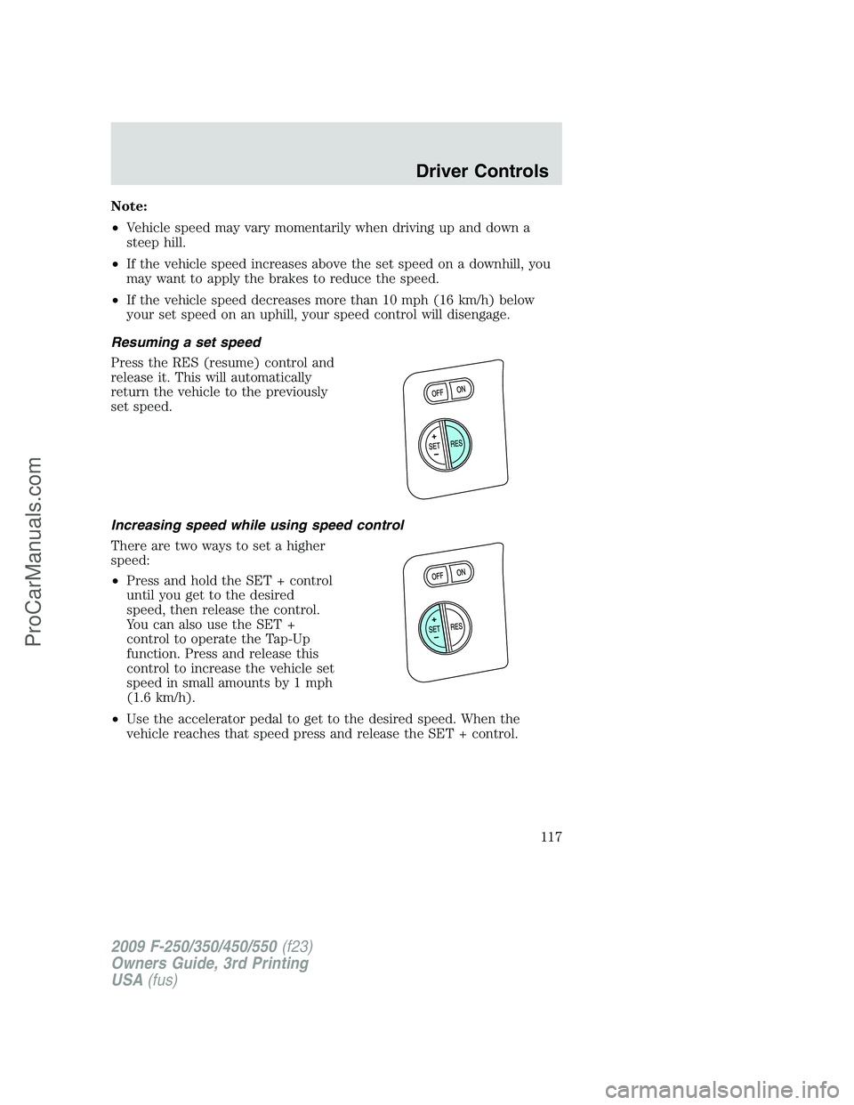
Press the RES (resume) control and
release it. This will automatically
return the vehicle to the previously
set speed.
Increasing speed while using speed control
There are two ways to set a higher
speed:
•Press and hold the SET + control
until you get to the desired
speed, then release the control.
You can also use the SET +
control to operate the Tap-Up
function. Press and release this
control to increase the vehicle set
speed in small amounts by 1 mph
(1.6 km/h).
•Use the accelerator pedal to get to the desired speed. When the
vehicle reaches that speed press and release the SET + control.
2009 F-250/350/450/550(f23)
Owners Guide, 3rd Printing
USA(fus)
Driver Controls
117
ProCarManuals.com
Page 147 of 419

REAR RIGHT DOOR AJAR— Displayed when the rear right door is
not completely closed.
FUEL LEVEL LOW— Displayed as an early reminder of a low fuel
condition.
WIRING FAULT ON TRAILER (if equipped)— Displayed and
accompanied by a single chime if there are certain faults in the vehicle
wiring and trailer wiring/brake system. Refer toTrailer towingin the
Tires, Wheels and Loadingchapter for more information.
TRAILER BRAKE MODULE FAULT (if equipped)— Displayed and
accompanied by a single chime in response to faults sensed by the TBC.
Refer toTrailer towingin theTires, Wheels and Loadingchapter for
more information.
TRAILER CONNECTED (if equipped)— Displayed when a correct
trailer connection (a trailer with electric trailer brakes) is sensed during
a given ignition cycle. Refer toTrailer towingin theTires, Wheels and
Loadingchapter for more information.
TRAILER DISCONNECTED (if equipped)— Displayed and
accompanied by a single chime when a trailer connection becomes
disconnected, either intentionally or unintentionally, and has been sensed
during a given ignition cycle. Refer toTrailer towingin theTires,
Wheels and Loadingchapter for more information.
BRAKE FLUID LEVEL LOW— Indicates the brake fluid level is low
and the brake system should be inspected immediately. Refer toBrake
fluidin theMaintenance and Specificationschapter.
LOW TIRE PRESSURE (if equipped)— Displayed when one or more
tires on your vehicle have low tire pressure. Refer toInflating Your
Tiresin theTires, Wheels and Loadingchapter.
TIRE PRESSURE MONITOR FAULT (if equipped)— Displayed
when the Tire Pressure Monitoring System is malfunctioning. If the
warning stays on or continues to come on, contact your authorized
dealer as soon as possible.
TIRE PRESSURE SENSOR FAULT (if equipped)— Displayed when
a tire pressure sensor is malfunctioning, or your spare tire is in use. For
more information on how the system operates under these conditions,
refer toUnderstanding Your Tire Pressure Monitoring System
(TPMS)in theTires, Wheels and Loadingchapter. If the warning stays
on or continues to come on, contact your authorized dealer as soon as
possible.
CHECK AIR FILTER (Diesel engine only)— Refer toInstrument
Clusterin your6.0 and 6.4 Liter Power Stroke Direct Injection Turbo
Diesel Owner’s Guide Supplement.
2009 F-250/350/450/550(f23)
Owners Guide, 3rd Printing
USA(fus)
Driver Controls
147
ProCarManuals.com
Page 183 of 419
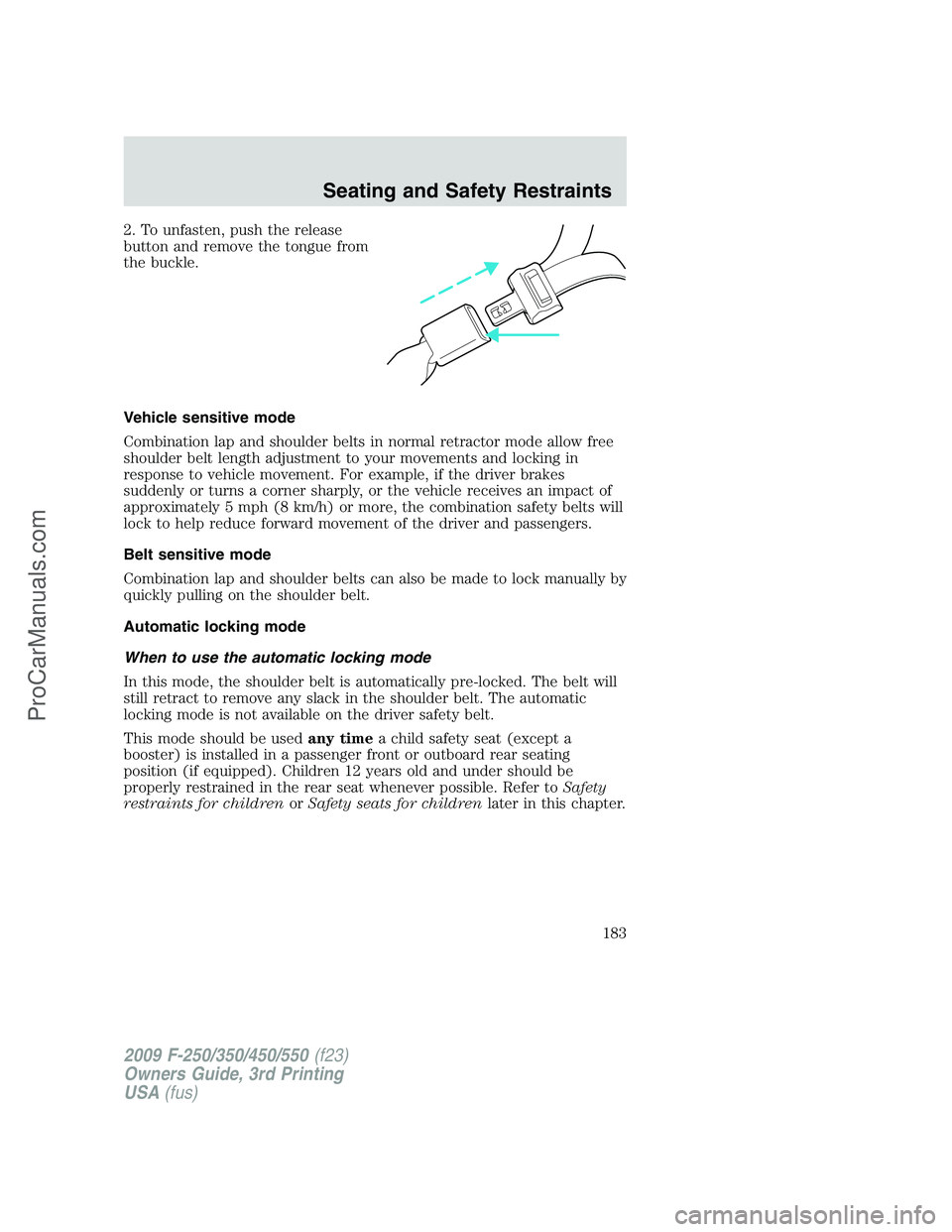
2. To unfasten, push the release
button and remove the tongue from
the buckle.
Vehicle sensitive mode
Combination lap and shoulder belts in normal retractor mode allow free
shoulder belt length adjustment to your movements and locking in
response to vehicle movement. For example, if the driver brakes
suddenly or turns a corner sharply, or the vehicle receives an impact of
approximately 5 mph (8 km/h) or more, the combination safety belts will
lock to help reduce forward movement of the driver and passengers.
Belt sensitive mode
Combination lap and shoulder belts can also be made to lock manually by
quickly pulling on the shoulder belt.
Automatic locking mode
When to use the automatic locking mode
In this mode, the shoulder belt is automatically pre-locked. The belt will
still retract to remove any slack in the shoulder belt. The automatic
locking mode is not available on the driver safety belt.
This mode should be usedany timea child safety seat (except a
booster) is installed in a passenger front or outboard rear seating
position (if equipped). Children 12 years old and under should be
properly restrained in the rear seat whenever possible. Refer toSafety
restraints for childrenorSafety seats for childrenlater in this chapter.
2009 F-250/350/450/550(f23)
Owners Guide, 3rd Printing
USA(fus)
Seating and Safety Restraints
183
ProCarManuals.com
Page 231 of 419
under-inflation of the tires, improper tires (load range, size, or type), or
vehicle modifications such as lift-kits. In the event that your vehicle
experiences shimmy, you should slowly reduce speed by either lifting off
the accelerator pedal or lightly applying the brakes. The shimmy will
cease as the vehicle speed decreases.
Maximum Permissible Inflation Pressureis the tire manufacturer’s
maximum permissible pressure and/or the pressure at which the
maximum load can be carried by the tire. This pressure is normally
higher than the manufacturer’s recommended cold inflation pressure
which can be found on the Safety Compliance Certification Label or Tire
Label which is located on the B-Pillar or the edge of the driver’s door.
The cold inflation pressure should never be set lower than the
recommended pressure on the Safety Compliance Certification Label or
Tire Label.
When weather temperature changes occur, tire inflation pressures also
change. A 10°F (6°C) temperature drop can cause a corresponding drop
of 1 psi (7 kPa) in inflation pressure. Check your tire pressures
frequently and adjust them to the proper pressure which can be found
on the Safety Compliance Certification Label or Tire Label.
To check the pressure in your tire(s):
1. Make sure the tires are cool, meaning they are not hot from driving
even a mile.
If you are checking tire pressure when the tire is hot, (i.e. driven more
than 1 mile [1.6 km]), never “bleed” or reduce air pressure. The tires are
hot from driving and it is normal for pressures to increase above
recommended cold pressures. A hot tire at or below recommended cold
inflation pressure could be significantly under-inflated.
Note:If you have to drive a distance to get air for your tire(s), check
and record the tire pressure first and add the appropriate air pressure
when you get to the pump. It is normal for tires to heat up and the air
pressure inside to go up as you drive.
2. Remove the cap from the valve on one tire, then firmly press the tire
gauge onto the valve and measure the pressure.
3. Add enough air to reach the recommended air pressure.
Note:If you overfill the tire, release air by pushing on the metal stem in
the center of the valve. Then recheck the pressure with your tire gauge.
4. Replace the valve cap.
5. Repeat this procedure for each tire, including the spare.
2009 F-250/350/450/550(f23)
Owners Guide, 3rd Printing
USA(fus)
Tires, Wheels and Loading
231
ProCarManuals.com
Page 259 of 419
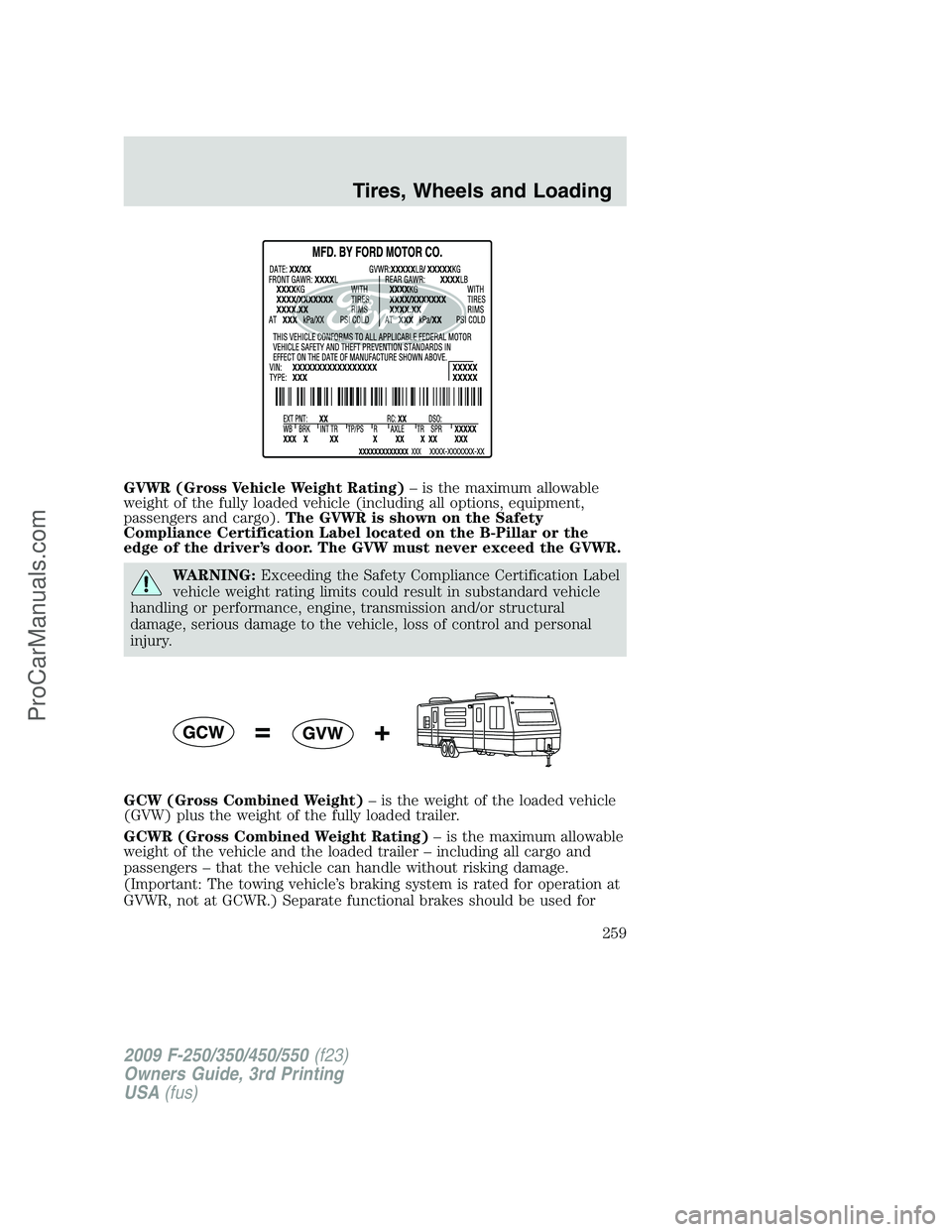
GVWR (Gross Vehicle Weight Rating)– is the maximum allowable
weight of the fully loaded vehicle (including all options, equipment,
passengers and cargo).The GVWR is shown on the Safety
Compliance Certification Label located on the B-Pillar or the
edge of the driver’s door. The GVW must never exceed the GVWR.
WARNING:Exceeding the Safety Compliance Certification Label
vehicle weight rating limits could result in substandard vehicle
handling or performance, engine, transmission and/or structural
damage, serious damage to the vehicle, loss of control and personal
injury.
GCW (Gross Combined Weight)– is the weight of the loaded vehicle
(GVW) plus the weight of the fully loaded trailer.
GCWR (Gross Combined Weight Rating)– is the maximum allowable
weight of the vehicle and the loaded trailer – including all cargo and
passengers – that the vehicle can handle without risking damage.
(Important: The towing vehicle’s braking system is rated for operation at
GVWR, not at GCWR.) Separate functional brakes should be used for
2009 F-250/350/450/550(f23)
Owners Guide, 3rd Printing
USA(fus)
Tires, Wheels and Loading
259
ProCarManuals.com
Page 263 of 419

the chart/table in the following text). This calculation will give you the
maximum trailer weight possible for your vehicle.
The weight of all additional cargo and passengers must be subtracted
from the maximum trailer weight calculated above.
Further trailer/hitch restrictions and limitations exist depending on the
type of trailer and hitch used. These additional maximum trailer weight
and tongue load limitations are listed in the chart/table that follows the
listing of GCWRs.
Towing a trailer places an additional load on your vehicle’s engine,
transmission, axle, brakes, tires and suspension. Inspect these
components carefully prior to and after any towing operation. Refer to
Transmission fluid temperature gaugein theInstrument Cluster
chapter for the transmission fluid temperature information.
Note:Do not exceed the GCWR listed for your vehicle on the following
chart/table, or the GVWR, GAWR or tire ratings specified on the Tire
Label or Safety Compliance Certification Label.
WARNING:Towing trailers beyond the maximum recommended
trailer weight which exceeds the limit of the vehicle’s GCWR,
GVWR, GAWR or tire ratings could result in engine damage,
transmission damage, structural damage, loss of vehicle control, vehicle
rollover and personal injury.
Maximum GCWR - lb. (kg.)
Engine Rear axle
ratioManual
transmissionAutomatic
transmission
F–250 Pick-up
5.4L 3.73 15000 (6804) 16000 (7257)
4.10 17000 (7711) 18000 (8165)
6.8L 4.10 20000 (9072) 21000 (9525)
4.30 22000 (9979) 22500 (10206)
F–350 Single Rear Wheel (SRW) Pick-up
5.4L 3.73 15000 (6804) 16000 (7257)
4.10 17000 (7711) 18000 (8165)
6.8L 4.10 20000 (9072) 21000 (9525)
4.30 22000 (9979) 23000 (10433)
2009 F-250/350/450/550(f23)
Owners Guide, 3rd Printing
USA(fus)
Tires, Wheels and Loading
263
ProCarManuals.com
Page 267 of 419
2. Measure the height of a reference point on the front and rear bumpers
at the center of the vehicle.
3. Attach the trailer to the vehicle and adjust the hitch equalizers so that
the front bumper height is within
1�2inch (13 mm) of the reference
point. After proper adjustment, the rear bumper should be no higher
than in Step 2.
WARNING:Do not adjust a weight distributing hitch to any
position where the rear bumper of the vehicle is higher than it
was before attaching the trailer. Doing so will defeat the function of
the weight distributing hitch, which may cause unpredictable handling,
and could result in serious personal injury.
Safety chains
Always connect the trailer’s safety chains to the frame or hook retainers
of the vehicle hitch. To connect the trailer’s safety chains, cross the
chains under the trailer tongue and allow slack for turning corners.
If you use a rental trailer, follow the instructions that the rental agency
gives to you.
Do not attach safety chains to the bumper.
Trailer brakes
Electric brakes and manual, automatic or surge-type trailer brakes are
safe if installed properly and adjusted to the manufacturer’s
specifications. The trailer brakes must meet local and Federal
regulations.
WARNING:If you own a trailer with a hydraulic brake system,
do not connect the trailer’s hydraulic brake system directly to
your vehicle’s brake system. The vehicle’s brake system is only
designed to carry the appropriate amount of brake fluid for the vehicle
alone. Connecting a hydraulic trailer braking system could adversely
affect your vehicle’s braking performance.
The braking system of the tow vehicle is rated for operation at the
GVWR not GCWR.
Integrated trailer brake controller (if equipped)
Your vehicle may be equipped with a fully integrated electronic Trailer
Brake Controller (TBC). When used properly, the TBC helps ensure
2009 F-250/350/450/550(f23)
Owners Guide, 3rd Printing
USA(fus)
Tires, Wheels and Loading
267
ProCarManuals.com