Page 298 of 419
The 4WD system:
•provides 4x4 High engagement and disengagement while the vehicle is
moving.
•is operated by a rotary control located on the instrument panel that
allows you select 2WD, 4x4 High or 4x4 Low operation.
•uses auto-manual hub locks that can be engaged and disengaged
automatically based on the 4x4 mode selected.
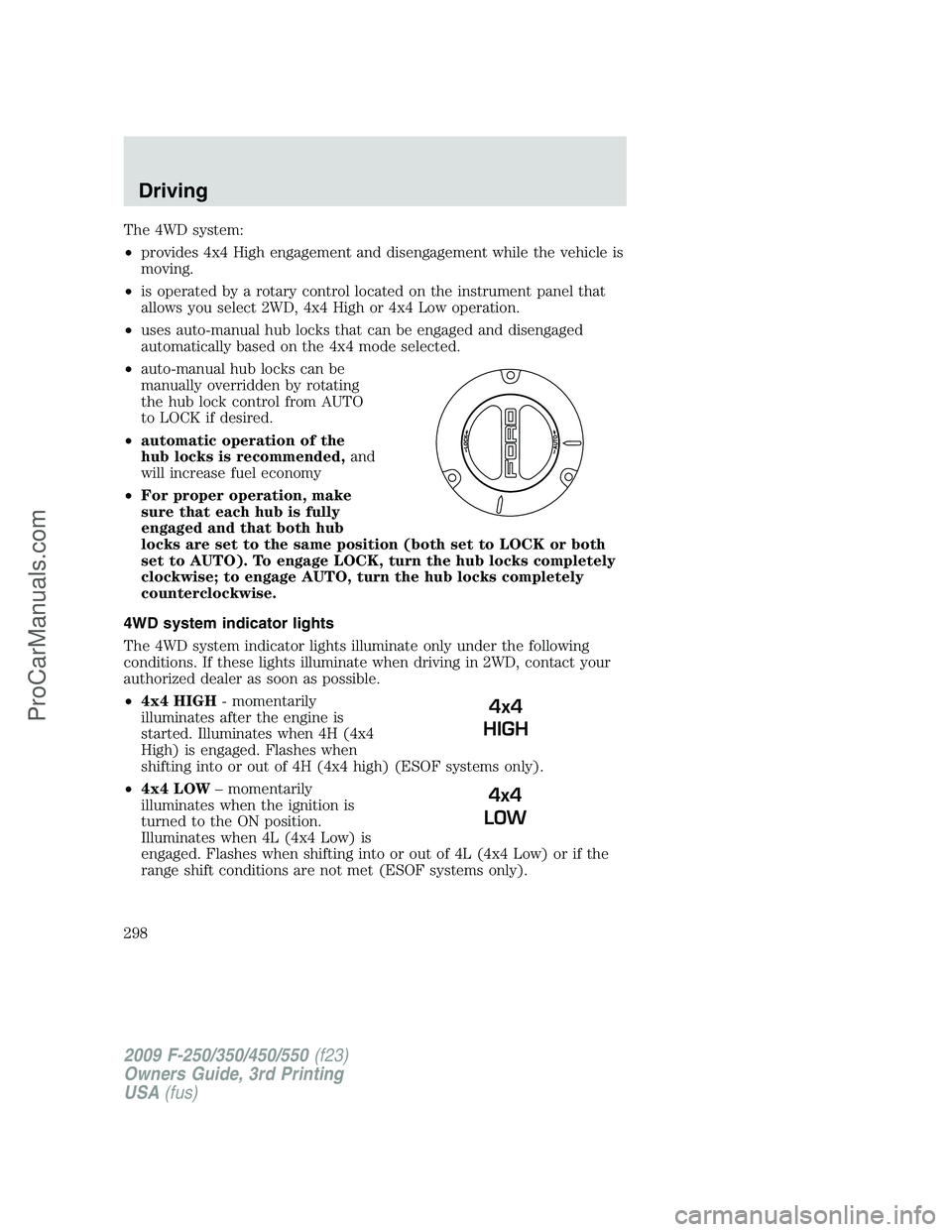
•auto-manual hub locks can be
manually overridden by rotating
the hub lock control from AUTO
to LOCK if desired.
•automatic operation of the
hub locks is recommended,and
will increase fuel economy
•For proper operation, make
sure that each hub is fully
engaged and that both hub
locks are set to the same position (both set to LOCK or both
set to AUTO). To engage LOCK, turn the hub locks completely
clockwise; to engage AUTO, turn the hub locks completely
counterclockwise.
4WD system indicator lights
The 4WD system indicator lights illuminate only under the following
conditions. If these lights illuminate when driving in 2WD, contact your
authorized dealer as soon as possible.
•4x4 HIGH- momentarily
illuminates after the engine is
started. Illuminates when 4H (4x4
High) is engaged. Flashes when
shifting into or out of 4H (4x4 high) (ESOF systems only).
•4x4 LOW– momentarily
illuminates when the ignition is
turned to the ON position.
Illuminates when 4L (4x4 Low) is
engaged. Flashes when shifting into or out of 4L (4x4 Low) or if the
range shift conditions are not met (ESOF systems only).
4x4
HIGH
4x4
LOW
2009 F-250/350/450/550(f23)
Owners Guide, 3rd Printing
USA(fus)
Driving
298
ProCarManuals.com
Page 332 of 419
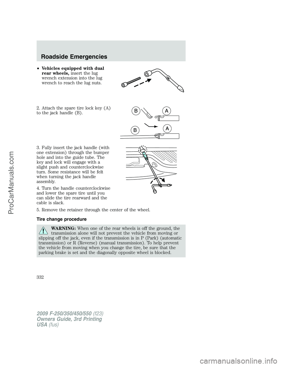
•Vehicles equipped with dual
rear wheels,insert the lug
wrench extension into the lug
wrench to reach the lug nuts.
2. Attach the spare tire lock key (A)
to the jack handle (B).
3. Fully insert the jack handle (with
one extension) through the bumper
hole and into the guide tube. The
key and lock will engage with a
slight push and counterclockwise
turn. Some resistance will be felt
when turning the jack handle
assembly.
4. Turn the handle counterclockwise
and lower the spare tire until you
can slide the tire rearward and the
cable is slack.
5. Remove the retainer through the center of the wheel.
Tire change procedure
WARNING:When one of the rear wheels is off the ground, the
transmission alone will not prevent the vehicle from moving or
slipping off the jack, even if the transmission is in P (Park) (automatic
transmission) or R (Reverse) (manual transmission). To help prevent
the vehicle from moving when you change the tire, be sure that the
parking brake is set and the diagonally opposite wheel is blocked.
2009 F-250/350/450/550(f23)
Owners Guide, 3rd Printing
USA(fus)
Roadside Emergencies
332
ProCarManuals.com
Page 333 of 419
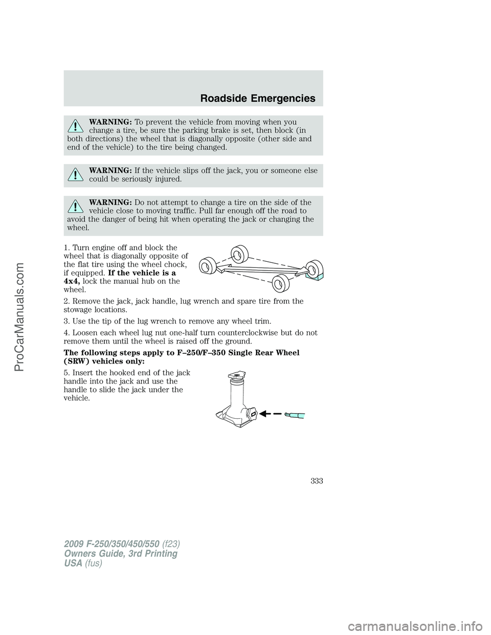
WARNING:To prevent the vehicle from moving when you
change a tire, be sure the parking brake is set, then block (in
both directions) the wheel that is diagonally opposite (other side and
end of the vehicle) to the tire being changed.
WARNING:If the vehicle slips off the jack, you or someone else
could be seriously injured.
WARNING:Do not attempt to change a tire on the side of the
vehicle close to moving traffic. Pull far enough off the road to
avoid the danger of being hit when operating the jack or changing the
wheel.
1. Turn engine off and block the
wheel that is diagonally opposite of
the flat tire using the wheel chock,
if equipped.If the vehicle is a
4x4,lock the manual hub on the
wheel.
2. Remove the jack, jack handle, lug wrench and spare tire from the
stowage locations.
3. Use the tip of the lug wrench to remove any wheel trim.
4. Loosen each wheel lug nut one-half turn counterclockwise but do not
remove them until the wheel is raised off the ground.
The following steps apply to F–250/F–350 Single Rear Wheel
(SRW) vehicles only:
5. Insert the hooked end of the jack
handle into the jack and use the
handle to slide the jack under the
vehicle.
2009 F-250/350/450/550(f23)
Owners Guide, 3rd Printing
USA(fus)
Roadside Emergencies
333
ProCarManuals.com
Page 335 of 419

•Rear
Never use the front or rear
differential as a jacking point.
WARNING:To lessen the
risk of personal injury, do
not put any part of your body
under the vehicle while changing a
tire. Do not start the engine when
your vehicle is on the jack. The
jack is only meant for changing
the tire.
7. Turn the jack handle clockwise
until the wheel is completely off the
ground and high enough to install
the spare tire.
8. Remove the lug nuts with the lug
wrench.
9. Replace the flat tire with the
spare tire, making sure the valve
stem is facing outward for all front wheels and single rear wheel vehicles.
If replacing an inboard rear tire on dual rear wheel vehicles, the valve
stem must be facing outward. If replacing the outboard wheel, the valve
stem must be facing inward. Reinstall the lug nuts until the wheel is
snug against the hub. Do not fully tighten the lug nuts until the wheel
has been lowered.
2009 F-250/350/450/550(f23)
Owners Guide, 3rd Printing
USA(fus)
Roadside Emergencies
335
ProCarManuals.com
Page 336 of 419
10. Lower the wheel by turning the jack handle counterclockwise.
Go to step 19.
The following steps apply to F–350 Dual Rear Wheel (DRW) and
F–450/F–550 vehicles only:
11. Slide the notched end of the
jack handle over the release valve
and use the handle to slide the jack
under the vehicle. Make sure the
valve is closed by turning it
clockwise.
12. Position the jack according to
the following guides:
•Front (4x2): F–350 DRW
Note:Place jack directly under
I-beam.
•Front driver side (4x4): F–350
DRW
Note:Make sure the jack fits onto
the flat area on the outboard side of
the differential housing.
2009 F-250/350/450/550(f23)
Owners Guide, 3rd Printing
USA(fus)
Roadside Emergencies
336
ProCarManuals.com
Page 338 of 419
13. Insert the jack handle into the
pump linkage.
14. Use an up-and-down motion
with the jack handle to raise the
wheel completely off the ground.
Hydraulic jacks are equipped
with a pressure release valve
that prevents lifting loads which
exceed the jack’s rated capacity.
15. Remove the lug nuts with the lug wrench.
16. Replace the flat tire with the spare tire, making sure the valve stem
is facing outward on all front an inboard rear wheels. If replacing the
outboard wheel, the valve stem must be facing inward. Reinstall the lug
nuts until the wheel is snug against the hub. Do not fully tighten the lug
nuts until the wheel has been lowered.
17. Lower the wheel by slowly turning the release valve
counterclockwise. Opening the release valve slowly will provide a more
controlled rate of descent.
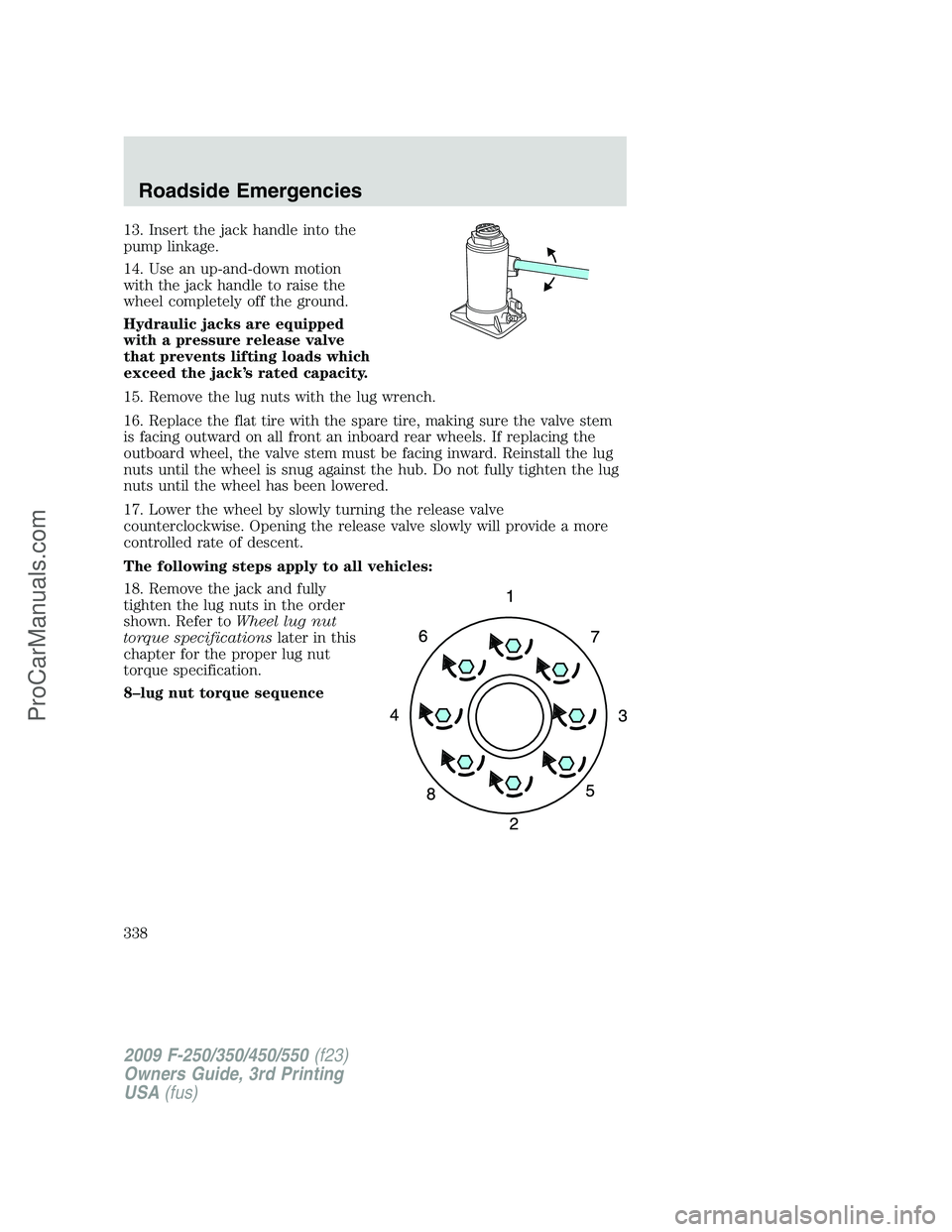
The following steps apply to all vehicles:
18. Remove the jack and fully
tighten the lug nuts in the order
shown. Refer toWheel lug nut
torque specificationslater in this
chapter for the proper lug nut
torque specification.
8–lug nut torque sequence
2009 F-250/350/450/550(f23)
Owners Guide, 3rd Printing
USA(fus)
Roadside Emergencies
338
ProCarManuals.com
Page 341 of 419
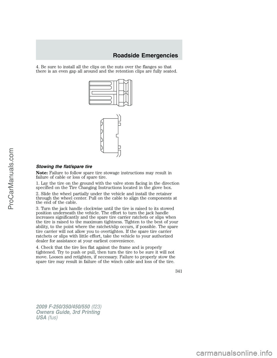
4. Be sure to install all the clips on the nuts over the flanges so that
there is an even gap all around and the retention clips are fully seated.
Stowing the flat/spare tire
Note:Failure to follow spare tire stowage instructions may result in
failure of cable or loss of spare tire.
1. Lay the tire on the ground with the valve stem facing in the direction
specified on the Tire Changing Instructions located in the glove box.
2. Slide the wheel partially under the vehicle and install the retainer
through the wheel center. Pull on the cable to align the components at
the end of the cable.
3. Turn the jack handle clockwise until the tire is raised to its stowed
position underneath the vehicle. The effort to turn the jack handle
increases significantly and the spare tire carrier ratchets or slips when
the tire is raised to the maximum tightness. Tighten to the best of your
ability, to the point where the ratchet/slip occurs, if possible. The spare
tire carrier will not allow you to overtighten. If the spare tire carrier
ratchets or slips with little effort, take the vehicle to your authorized
dealer for assistance at your earliest convenience.
4. Check that the tire lies flat against the frame and is properly
tightened. Try to push or pull, then turn the tire to be sure it will not
move. Loosen and retighten, if necessary. Failure to properly stow the
spare tire may result in failure of the winch cable and loss of the tire.
2009 F-250/350/450/550(f23)
Owners Guide, 3rd Printing
USA(fus)
Roadside Emergencies
341
ProCarManuals.com
Page 374 of 419
4. Install the dipstick and ensure it is fully seated.
5. Fully install the engine oil filler cap by turning the filler cap clockwise
1/4 of a turn until three clicks are heard or until the cap is fully seated.
To avoid possible oil loss, DO NOT operate the vehicle with the
engine oil level dipstick and/or the engine oil filler cap removed.
Engine oil and filter recommendations
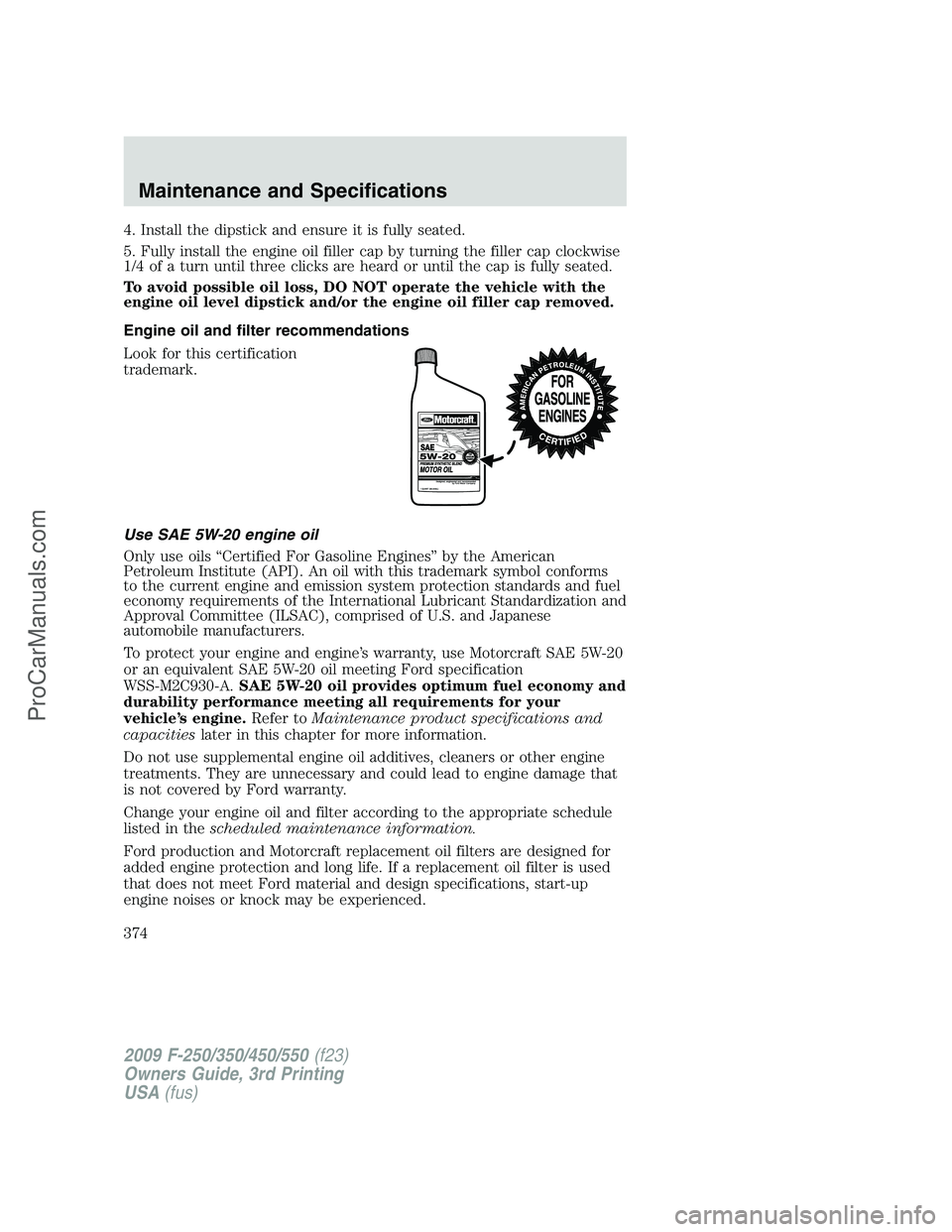
Look for this certification
trademark.
Use SAE 5W-20 engine oil
Only use oils “Certified For Gasoline Engines” by the American
Petroleum Institute (API). An oil with this trademark symbol conforms
to the current engine and emission system protection standards and fuel
economy requirements of the International Lubricant Standardization and
Approval Committee (ILSAC), comprised of U.S. and Japanese
automobile manufacturers.
To protect your engine and engine’s warranty, use Motorcraft SAE 5W-20
or an equivalent SAE 5W-20 oil meeting Ford specification
WSS-M2C930-A.SAE 5W-20 oil provides optimum fuel economy and
durability performance meeting all requirements for your
vehicle’s engine.Refer toMaintenance product specifications and
capacitieslater in this chapter for more information.
Do not use supplemental engine oil additives, cleaners or other engine
treatments. They are unnecessary and could lead to engine damage that
is not covered by Ford warranty.
Change your engine oil and filter according to the appropriate schedule
listed in thescheduled maintenance information.
Ford production and Motorcraft replacement oil filters are designed for
added engine protection and long life. If a replacement oil filter is used
that does not meet Ford material and design specifications, start-up
engine noises or knock may be experienced.
2009 F-250/350/450/550(f23)
Owners Guide, 3rd Printing
USA(fus)
Maintenance and Specifications
374
ProCarManuals.com