2009 FORD CROWN VICTORIA suspension
[x] Cancel search: suspensionPage 164 of 271
to transport the cement to your home? If you and your friend each
weigh 220 lb. (99 kg), the calculation would be: 1,400 - (2 x 220) -
(12 x 100) = 1,400 - 440 - 1,200 = - 240 lb. No, you do not have
enough cargo capacity to carry that much weight. In metric units, the
calculation would be: 635 kg - (2 x 99 kg) - (12 x 45 kg) = 635 - 198 -
540 = -103 kg. You will need to reduce the load weight by at least
240 lb. (104 kg). If you remove 3-100 lb. (45 kg) cement bags, then
the load calculation would be:
1,400 - (2 x 220) - (9 x 100) = 1,400 - 440 - 900 = 60 lb. Now you
have the load capacity to transport the cement and your friend home.
In metric units, the calculation would be: 635 kg - (2 x 99 kg) - (9 x
45 kg) = 635 - 198 - 405 = 32 kg.
The above calculations also assume that the loads are positioned in your
vehicle in a manner that does not overload the Front or the Rear Gross
Axle Weight Rating specified for your vehicle on the Safety Compliance
Certification Label found on the edge of the driver’s door.
TRAILER TOWING
Note:Long wheel based vehicles are NOT rated for towing.
Your vehicle is classified as a light duty towing vehicle. Do not tow a
trailer until your vehicle has been driven at least 1,000 miles (1,600 km).
Towing a trailer places an additional load on your vehicle’s engine,
transmission, brakes, tires and suspension. Inspect these components
carefully after towing.
Your loaded trailer should weigh no more than 1,500 lb. (680 kg).Do
not exceed the GVWR specified on the Safety Compliance
Certification Label.
WARNING:Towing trailers beyond the maximum recommended
gross trailer weight exceeds the limit of the vehicle and could
result in engine damage, transmission damage, structural damage, loss
of vehicle control, vehicle rollover and personal injury.
The GCW of your vehicle and trailer should not exceed 6,600 lb.
(2,993 kg).
Preparing to tow
Use the proper equipment for towing a trailer and make sure it is
properly attached to your vehicle. Contact your authorized dealer or a
reliable trailer dealer as soon as possible if you require assistance.
2009 Crown Victoria(cro)
Owners Guide, 2nd Printing
USA(fus)
Tires, Wheels and Loading
164
Page 178 of 271
STEERING
To help prevent damage to the power steering system, never hold the
steering wheel at its furthest turning points (until it stops) for more than
a few seconds when the engine is running.
It is also important to maintain a proper power steering fluid level in the
power steering fluid reservoir:
•Do not operate the vehicle with a low power steering pump fluid level.
SeePower steering fluidin theMaintenance and Specifications
chapter.
•Some noise is normal during operation. If the noise is excessive, check
for low power steering pump fluid level before seeking service by your
authorized dealer.
•Heavy or uneven steering efforts may be caused by low power steering
pump fluid level. Check for low power steering pump fluid level before
seeking service by your authorized dealer.
•Do not fill the power steering pump reservoir above the maximum
level, as this may result in leaks from the reservoir. SeePower
steering fluidin theMaintenance and Specificationschapter.
If the power steering system breaks down (or if the engine is off), you
can steer the vehicle manually, but it takes more effort.
If the steering wanders or pulls, check for:
•an improperly inflated tire
•uneven tire wear
•loose or worn suspension components
•loose or worn steering components
•improper steering alignment
AIR SUSPENSION SYSTEM (IF EQUIPPED)
The air suspension system is designed to improve ride, handling and
general vehicle performance during:
•Certain road conditions
•Steering maneuvers
•Braking
•Accelerations
This system keeps the rear of your vehicle at a constant level by
automatically adding air or releasing air from the springs.
2009 Crown Victoria(cro)
Owners Guide, 2nd Printing
USA(fus)
Driving
178
Page 179 of 271
If you exceed the load limit, the rear air suspension may not operate.
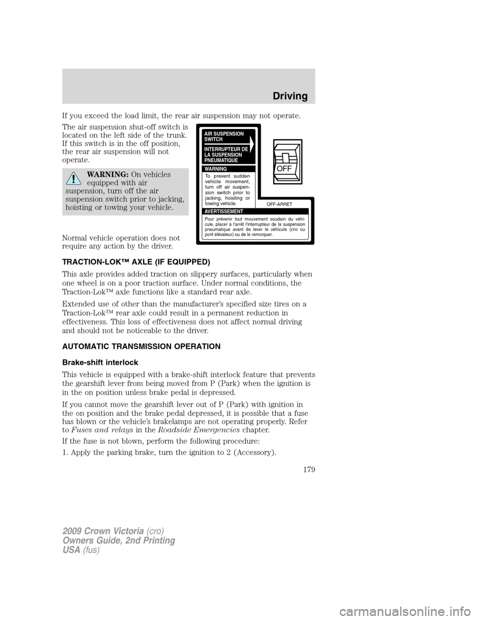
The air suspension shut-off switch is
located on the left side of the trunk.
If this switch is in the off position,
the rear air suspension will not
operate.
WARNING:On vehicles
equipped with air
suspension, turn off the air
suspension switch prior to jacking,
hoisting or towing your vehicle.
Normal vehicle operation does not
require any action by the driver.
TRACTION-LOK™ AXLE (IF EQUIPPED)
This axle provides added traction on slippery surfaces, particularly when
one wheel is on a poor traction surface. Under normal conditions, the
Traction-Lok™ axle functions like a standard rear axle.
Extended use of other than the manufacturer’s specified size tires on a
Traction-Lok™ rear axle could result in a permanent reduction in
effectiveness. This loss of effectiveness does not affect normal driving
and should not be noticeable to the driver.
AUTOMATIC TRANSMISSION OPERATION
Brake-shift interlock
This vehicle is equipped with a brake-shift interlock feature that prevents
the gearshift lever from being moved from P (Park) when the ignition is
in the on position unless brake pedal is depressed.
If you cannot move the gearshift lever out of P (Park) with ignition in
the on position and the brake pedal depressed, it is possible that a fuse
has blown or the vehicle’s brakelamps are not operating properly. Refer
toFuses and relaysin theRoadside Emergencieschapter.
If the fuse is not blown, perform the following procedure:
1. Apply the parking brake, turn the ignition to 2 (Accessory).
AIR SUSPENSION
SWITCH
INTERRUPTEUR DE
LA SUSPENSION
PNEUMATIQUE
WARNING
AVERTISSEMENTOFF-ARRET
To prevent sudden
vehicle movement,
turn off air suspen-
sion switch prior to
jacking, hoisting or
towing vehicle.
Pour prévenir tout mouvement soudain du véhi-
cule, placer à l'arrêt l'interrupteur de la suspension
pneumatique avant de lever le véhicule (cric ou
pont élévateur) ou de le remorquer.
OFF
2009 Crown Victoria(cro)
Owners Guide, 2nd Printing
USA(fus)
Driving
179
Page 189 of 271
Fuse/Relay
LocationFuse Amp
RatingProtected Circuits
1 10A Ignition (START) - Starter relay
coil, DTRS
2 7.5A Power mirrors, Mirror switch,
Keypad switch, Decklid switch,
DDM, Cluster
3 5A Ignition (START) - Audio mute,
Police PDB (Police vehicles only)
4 10A LCM (switch illumination),
Autolamp sensor
5 7.5A Ignition (ON/ACC) - LCM
6 7.5A LCM
7 10A Ignition (ON/ACC) - Wiper
module
8 10A Electronic Automatic Temperature
Control (EATC) module (vehicles
equipped with EATC only)
9 7.5A Ignition (ON/ACC) - Door lock
switch illumination, Heated seat
switch illumination, Radio,
Antenna, Electrochromatic mirror,
Window relay coil (non-Police
vehicles only), Window and
decklid relay coil and Police
ON/ACC relay coil (Police vehicles
only)
10 15A Hazards (non-Police vehicles
only)
20A Hazards (Police vehicles only)
11 15A Ignition (ON) - Turn signals
12 15A Audio
13 10A Ignition (ON) - Rear Air
Suspension Module (RASM),
Cluster
2009 Crown Victoria(cro)
Owners Guide, 2nd Printing
USA(fus)
Roadside Emergencies
189
Page 192 of 271
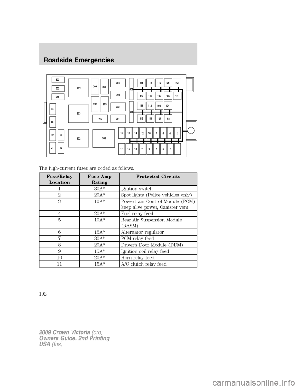
The high-current fuses are coded as follows.
Fuse/Relay
LocationFuse Amp
RatingProtected Circuits
1 30A* Ignition switch
2 20A* Spot lights (Police vehicles only)
3 10A* Powertrain Control Module (PCM)
keep alive power, Canister vent
4 20A* Fuel relay feed
5 10A* Rear Air Suspension Module
(RASM)
6 15A* Alternator regulator
7 30A* PCM relay feed
8 20A* Driver’s Door Module (DDM)
9 15A* Ignition coil relay feed
10 20A* Horn relay feed
11 15A* A/C clutch relay feed
503
502
501
24
23
20
19 22
21302303304
301 207201 202203 204
209
206
208
205602118
114
110
106
102
117
113
109
105
101
116
112
108
104
115
111
107
103
18
16
14
1210
8
6
4
2
17
15
13
119
7
5
3
1 601
2009 Crown Victoria(cro)
Owners Guide, 2nd Printing
USA(fus)
Roadside Emergencies
192
Page 194 of 271
Fuse/Relay
LocationFuse Amp
RatingProtected Circuits
108 20A** Police accessory battery feed 3
(Police vehicles only), Cigar
lighter (Non-police vehicles only)
109 20A** ABS module (Valves)
110 30A** Wiper module
111 50A** Police PDB or Police accessory
battery feed (Police vehicles only)
112 30A** Air suspension compressor
(non-Police vehicles only)
40A** Police PDB relay feed (Police
vehicles only)
113 50A** Police light bar or Police
right-hand kick panel accessory
battery feed (Police vehicles only)
114 50A** Police PDB or Police accessory
battery feed (Police vehicles only)
115 50A** Rear power point or Police
right-hand kick panel accessory
battery feed (Police vehicles only)
116 50A** Police accessory battery feed
(Police vehicles only)
117 50A** Police PDB or Police accessory
battery feed (Police vehicles only)
118 50A** Rear power point or Police
right-hand kick panel accessory
battery feed (Police vehicles only)
201
12ISO relay A/C clutch
202 — Not used
203
12ISO relay Ignition coil
204
12ISO relay PCM
205 — Not used
206
12ISO relay Fuel
2009 Crown Victoria(cro)
Owners Guide, 2nd Printing
USA(fus)
Roadside Emergencies
194
Page 199 of 271
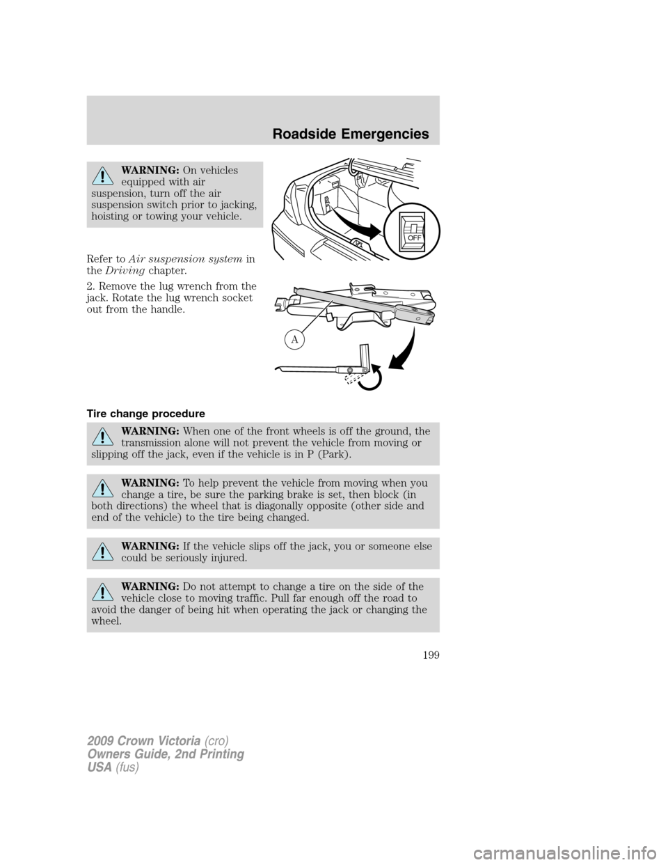
WARNING:On vehicles
equipped with air
suspension, turn off the air
suspension switch prior to jacking,
hoisting or towing your vehicle.
Refer toAir suspension systemin
theDrivingchapter.
2. Remove the lug wrench from the
jack. Rotate the lug wrench socket
out from the handle.
Tire change procedure
WARNING:When one of the front wheels is off the ground, the
transmission alone will not prevent the vehicle from moving or
slipping off the jack, even if the vehicle is in P (Park).
WARNING:To help prevent the vehicle from moving when you
change a tire, be sure the parking brake is set, then block (in
both directions) the wheel that is diagonally opposite (other side and
end of the vehicle) to the tire being changed.
WARNING:If the vehicle slips off the jack, you or someone else
could be seriously injured.
WARNING:Do not attempt to change a tire on the side of the
vehicle close to moving traffic. Pull far enough off the road to
avoid the danger of being hit when operating the jack or changing the
wheel.
OFF
A
2009 Crown Victoria(cro)
Owners Guide, 2nd Printing
USA(fus)
Roadside Emergencies
199
Page 201 of 271
WARNING:To lessen risk
of personal injury, do not
put any part of your body under
the vehicle while changing a tire.
Do not start the engine when your
vehicle is on the jack. The jack is
ONLY meant for changing the tire.
•Never use the rear differential
as a jacking point.
4. Remove the metal lug nuts with the lug wrench.
5. Replace the flat tire/wheel assembly with the spare tire/wheel
assembly, making sure the valve stem is facing outward. Reinstall lug
nuts until the wheel is snug against the hub. Do not fully tighten the lug
nuts until the wheel has been lowered.
6. Lower the vehicle by turning the jack handle counterclockwise.
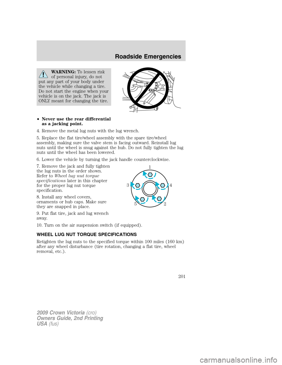
7. Remove the jack and fully tighten
the lug nuts in the order shown.
Refer toWheel lug nut torque
specificationslater in this chapter
for the proper lug nut torque
specification.
8. Install any wheel covers,
ornaments or hub caps. Make sure
they are snapped in place.
9. Put flat tire, jack and lug wrench
away.
10. Turn on the air suspension switch (if equipped).
WHEEL LUG NUT TORQUE SPECIFICATIONS
Retighten the lug nuts to the specified torque within 100 miles (160 km)
after any wheel disturbance (tire rotation, changing a flat tire, wheel
removal, etc.).
1
4 3
2 5
2009 Crown Victoria(cro)
Owners Guide, 2nd Printing
USA(fus)
Roadside Emergencies
201