2009 FIAT QUBO seats
[x] Cancel search: seatsPage 5 of 202

4
SAFETY
STARTING
AND DRIVING
WARNING
LIGHTS AND
MESSAGES
IN AN
EMERGENCY
MAINTENANCE
AND CARE
TECHNICAL
SPECIFICATIONS
INDEX
DASHBOARD
AND CONTROLSDASHBOARD........................................................................ 5
INSTRUMENT PANEL ......................................................... 6
SYMBOLS ............................................................................... 7
THE FIAT CODE SYSTEM ................................................. 7
THE KEYS .............................................................................. 8
ALARM ................................................................................... 11
IGNITION DEVICE ............................................................. 13
INSTRUMENTS .................................................................... 14
DIGITAL DISPLAY ............................................................... 16
MULTIFUNCTIONAL DISPLAY ...................................... 21
TRIP COMPUTER ................................................................ 30
SEATS ...................................................................................... 33
HEAD RESTRAINTS............................................................. 36
STEERING WHEEL .............................................................. 37
REARVIEW MIRRORS......................................................... 37
HEATING AND CLIMATE CONTROL SYSTEM ........ 39
HEATING AND VENTILATION ...................................... 41
MANUAL CLIMATE CONTROL SYSTEM .................... 44
EXTERNAL LIGHTS ............................................................ 47WINDOW WASHING....................................................... 49
CEILING LIGHTS.................................................................. 51
CONTROLS ........................................................................... 54
INTERIOR FITTINGS........................................................... 56
DOORS .................................................................................. 59
WINDOW WINDERS ....................................................... 63
BOOT ...................................................................................... 64
BONNET................................................................................. 68
ROOF RACK/SKI RACK .................................................... 69
HEADLIGHTS........................................................................ 70
ABS SYSTEM ......................................................................... 71
ESP SYSTEM .......................................................................... 72
TRACTION PLUS SYSTEM ............................................... 75
EOBD SYSTEM ..................................................................... 76
PARKING SENSORS ........................................................... 77
SOUND SYSTEM.................................................................. 79
ELECTRICAL/ELECTRONIC DEVICES
INSTALLATION.................................................................... 80
AT THE FILLING STATION.............................................. 80
ENVIRONMENTAL PROTECTION................................. 82
D D
A A
S S
H H
B B
O O
A A
R R
D D
A A
N N
D D
C C
O O
N N
T T
R R
O O
L L
S S
001-035 QUBO GB 1ed:001-035 Fiorino GB 1ed 3-12-2009 15:58 Pagina 4
Page 34 of 202

33
SAFETY
STARTING
AND DRIVING
WARNING
LIGHTS AND
MESSAGES
IN AN
EMERGENCY
MAINTENANCE
AND CARE
TECHNICAL
SPECIFICATIONS
INDEX
DASHBOARD
AND CONTROLS
fig. 19F0T0153m
SEATS
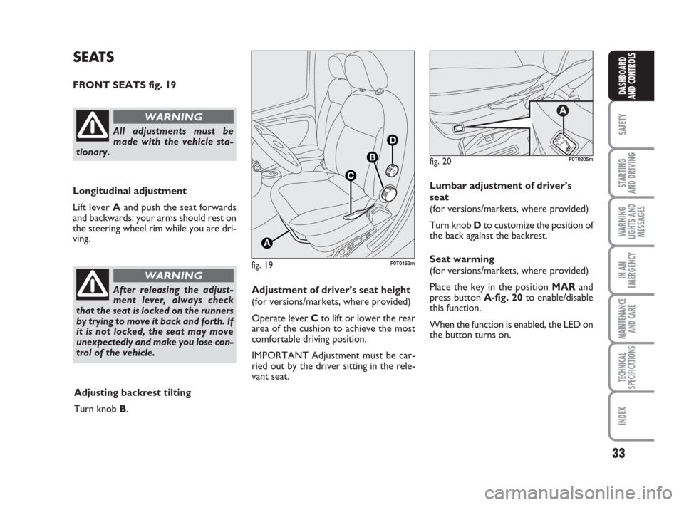
FRONT SEATS fig. 19
Longitudinal adjustment
Lift lever Aand push the seat forwards
and backwards: your arms should rest on
the steering wheel rim while you are dri-
ving.
All adjustments must be
made with the vehicle sta-
tionary.
WARNING
After releasing the adjust-
ment lever, always check
that the seat is locked on the runners
by trying to move it back and forth. If
it is not locked, the seat may move
unexpectedly and make you lose con-
trol of the vehicle.
WARNING
Adjustment of driver’s seat height
(for versions/markets, where provided)
Operate lever Cto lift or lower the rear
area of the cushion to achieve the most
comfortable driving position.
IMPORTANT Adjustment must be car-
ried out by the driver sitting in the rele-
vant seat.
Adjusting backrest tilting
Turn knob B.Lumbar adjustment of driver’s
seat
(for versions/markets, where provided)
Turn knob Dto customize the position of
the back against the backrest.
Seat warming
(for versions/markets, where provided)
Place the key in the position MARand
press button A-fig. 20to enable/disable
this function.
When the function is enabled, the LED on
the button turns on.
fig. 20
A
F0T0205m
001-035 QUBO GB 1ed:001-035 Fiorino GB 1ed 3-12-2009 15:59 Pagina 33
Page 35 of 202

34
SAFETY
STARTING
AND DRIVING
WARNING
LIGHTS AND
MESSAGES
IN AN
EMERGENCY
MAINTENANCE
AND CARE
TECHNICAL
SPECIFICATIONS
INDEX
DASHBOARD
AND CONTROLS
RECESSING FOLDABLE
PASSENGER’S SEAT
(for versions/markets, where provided)
Some versions have the passenger’s seat
which folds into a recessed compartment.
IMPORTANT Only move the seat if there
are no passengers in the rear seats.
Folding the seat
To fold the seat proceed as follows:
❒open the door on the passenger’s side;
❒pull the two levers A-fig. 21on the
sides of the seat and tip it forward fol-
lowing the indications of the arrow;
❒then, push the backrest B-fig. 22down:
the seat is now folded all the way down
in the “table” position;
❒pull the lever C-fig. 23and push the
backrest down as much as possible: the
seat is now completely folded.
fig. 21F0T0274m
fig. 22F0T0163m
fig. 23F0T0164m
001-035 QUBO GB 1ed:001-035 Fiorino GB 1ed 3-12-2009 15:59 Pagina 34
Page 36 of 202

35
SAFETY
STARTING
AND DRIVING
WARNING
LIGHTS AND
MESSAGES
IN AN
EMERGENCY
MAINTENANCE
AND CARE
TECHNICAL
SPECIFICATIONS
INDEX
DASHBOARD
AND CONTROLS
fig. 24F0T0165mfig. 25F0T0237m
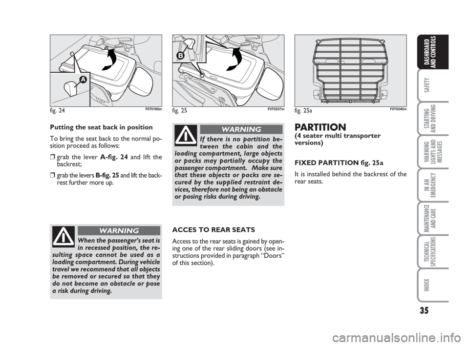
Putting the seat back in position
To bring the seat back to the normal po-
sition proceed as follows:
❒grab the lever A-fig. 24and lift the
backrest;
❒grab the levers B-fig. 25and lift the back-
rest further more up.
When the passenger’s seat is
in recessed position, the re-
sulting space cannot be used as a
loading compartment. During vehicle
travel we recommend that all objects
be removed or secured so that they
do not become an obstacle or pose
a risk during driving.
WARNING
If there is no partition be-
tween the cabin and the
loading compartment, large objects
or packs may partially occupy the
passenger compartment. Make sure
that these objects or packs are se-
cured by the supplied restraint de-
vices, therefore not being an obstacle
or posing risks during driving.
WARNING
ACCES TO REAR SEATS
Access to the rear seats is gained by open-
ing one of the rear sliding doors (see in-
structions provided in paragraph “Doors”
of this section).
fig. 25aF0T0340m
PARTITION(4 seater multi transporter
versions)
FIXED PARTITION fig. 25a
It is installed behind the backrest of the
rear seats.
001-035 QUBO GB 1ed:001-035 Fiorino GB 1ed 3-12-2009 15:59 Pagina 35
Page 65 of 202

64
SAFETY
STARTING
AND DRIVING
WARNING
LIGHTS AND
MESSAGES
IN AN
EMERGENCY
MAINTENANCE
AND CARE
TECHNICAL
SPECIFICATIONS
INDEX
DASHBOARD
AND CONTROLS
BOOT
BOOT OPENING
FROM OUTSIDE
The tailgate (when unlocked) can only be
opened from outside using the powered
handle A-fig. 71located beneath the
shackle.
If doors are unlocked the boot can be
opened at any time.
To open it, one of the front doors shall be
opened or doors shall be unlocked using
the remote control or the key without re-
mote control.
fig. 71
A
F0T0250m
Never exceed the maximum
allowed load in the boot (see
section “Technical Specifications”).
Make sure that the objects are well
arranged in the boot so that they will
not be projected forwards following
sudden braking.
WARNING
If you travel in areas with
few filling stations and you
want to transport fuel in a spare tank,
respect applicable laws and exclu-
sively use a type-approved suitably
secured tank. However, the risks in
case of collision increase.
WARNING
fig. 72
A
F0T0285m
EMERGENCY OPENING
FROM INSIDE
In case of emergency the boot can be
opened from inside the vehicle as de-
scribed below.
❒Open the sliding side door and fold the
rear seats over completely;
❒working inside the luggage compart-
ment, press lever A-fig. 72and open
the tailgate.
036-082 QUBO GB 1ed:_ 3-12-2009 11:55 Pagina 64
Page 66 of 202

65
SAFETY
STARTING
AND DRIVING
WARNING
LIGHTS AND
MESSAGES
IN AN
EMERGENCY
MAINTENANCE
AND CARE
TECHNICAL
SPECIFICATIONS
INDEX
DASHBOARD
AND CONTROLS
REMOVING THE REAR
WINDOW SHELF
The rear window shelf fig. 73consists of
two parts. To remove it proceed as fol-
lows:
❒open the luggage compartment tailage,
lift up the front section A-fig. 74re-
leasing the pin A-fig. 75from the hous-
ing B-fig. 76;
❒lift the rear section B-fig. 74releasing
the pins Band C-fig. 75from the hous-
ings Dand E-fig. 76;If the seat is completely folded, remove
the rear window shelf as described above
and position it between the backrests of
the front seats and the tipped rear seat.
The rear window shelf is fit back into place
by carrying out the operations described
above in reverse order.
fig. 73F0T0061mfig. 74
A
A
F0T0062m
fig. 75
AAA
F0T0063m
Under no circumstances
should the rear seat be used
with the backrest tipped for carrying
cargos or luggage. The cargo may
crash against the backrest of the front
seats, thus causing serious injury to
passengers.
WARNING
fig. 76
D
E
B
F0T0287m
036-082 QUBO GB 1ed:_ 3-12-2009 11:55 Pagina 65
Page 67 of 202

66
SAFETY
STARTING
AND DRIVING
WARNING
LIGHTS AND
MESSAGES
IN AN
EMERGENCY
MAINTENANCE
AND CARE
TECHNICAL
SPECIFICATIONS
INDEX
DASHBOARD
AND CONTROLS
EXPANDING THE BOOT
Proceed as follows:
❒open the luggage compartment tailgate
and remove the rear parcel shelf (see
description in previous paragraph);
❒lower the rear seat head restraints all
the way down;❒move the seat belt sideways and check
that it is stretched and presents no
twisting;
❒raise lever A-fig. 77retaining the back-
rest and fold it forwards to create an
even load compartment. The raising of
the lever is shown by a “red band” B;Versions with one-piece rear seat
To extend the luggage compartment fur-
ther, pull the tab A-fig. 78behind the rear
seat backrest and fold the seat and back-
rest forwards fig. 79.
Versions with split rear seat
To extend the luggage compartment fur-
ther, pull the tabs Aand B-fig. 80behind
the rear seat backrests and fold the seats
and backrests forwards fig. 81.
NoteThe one-piece and split seats have
circlips on the rear edge of the cushion for
attaching the seat to the front seat head
restraint rods when it is folded over.
fig. 78F0T0065m
fig. 79F0T0066mfig. 77
A
B
F0T0288m
fig. 80
AB
F0T0289m
fig. 81F0T0290m
036-082 QUBO GB 1ed:_ 3-12-2009 11:55 Pagina 66
Page 71 of 202

70
SAFETY
STARTING
AND DRIVING
WARNING
LIGHTS AND
MESSAGES
IN AN
EMERGENCY
MAINTENANCE
AND CARE
TECHNICAL
SPECIFICATIONS
INDEX
DASHBOARD
AND CONTROLS
HEADLIGHTS
DIRECTING THE BEAM
Correct direction of the headlights is es-
sential for the comfort and safety of the
driver and the other road users. To en-
sure the best visibility conditions during
travel with the headlights on the vehicle
must have beams aimed correctly. Con-
tact the Fiat Dealership to have the head-
lights checked and properly adjusted.
HEADLIGHT AIMING DEVICE
This device works with the key at MAR
and the dipped beam headlights on.
The vehicle slants backwards when it is
loaded, raising the beam. The beams must
therefore be directed again in this case.FOG LIGHT AIMING DEVICE
(for versions/markets, where provided)
Contact the Fiat Dealership to have the
fog lights checked and properly adjusted.
REGULATING THE BEAMS
ABROAD
Dipped beams factory adjustment depends
on the country where the vehicle is pur-
chased. In countries driving on the left, the
beams are aimed by affixing a purposeful-
ly studied adhesive film in order not to
dazzle the vehicles travelling in the oppo-
site direction. This adhesive film is pro-
vided in Lineaccessori Fiat and is available
at the Fiat Dealership. Headlight aiming device regulation
To adjust, press buttons Òand
fig. 92
on the control panel.
The display located on the instrument pan-
el provides a visual indication of the posi-
tions during adjustment operations.
Position 0 - one or two passengers on
front seats.
Position 1 - five passengers.
Position 2 - five passengers + loaded
boot.
Position 3 - driver + maximum admitted
cargo in the boot.
IMPORTANT Check beam aiming when-
ever the weight of the load carried
changes.
fig. 92F0T0037m
036-082 QUBO GB 1ed:_ 3-12-2009 11:55 Pagina 70