2009 FIAT PANDA rear wheel
[x] Cancel search: rear wheelPage 4 of 226

3KNOW YOUR
VEHICLESAFETY
CORRECT USE
OF THE CAR
WARNING LIGHTS
AND MESSAGES
IN
AN EMERGENCY
CAR
MAINTENANCE
TECHNICAL
SPECIFICATIONS
INDEX
KNOW YOUR VEHICLE
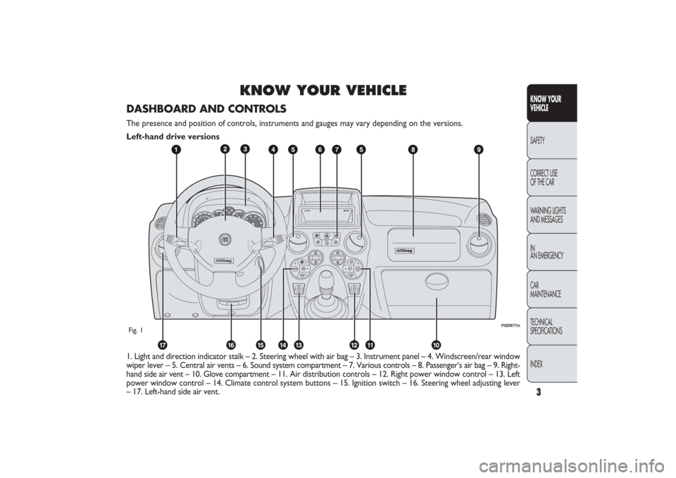
1. Light and direction indicator stalk – 2. Steering wheel with air bag – 3. Instrument panel – 4. Windscreen/rear window
wiper lever – 5. Central air vents – 6. Sound system compartment – 7. Various controls – 8. Passenger’s air bag – 9. Right-
hand side air vent – 10. Glove compartment – 11. Air distribution controls – 12. Right power window control – 13. Left
power window control – 14. Climate control system buttons – 15. Ignition switch – 16. Steering wheel adjusting lever
– 17. Left-hand side air vent.
F0Z0677m
Fig. 1DASHBOARD AND CONTROLSThe presence and position of controls, instruments and gauges may vary depending on the versions.
Left-hand drive versions
001-030 PANDA EN 7-10-2009 13:39 Pagina 3
Page 5 of 226

4
KNOW YOUR
VEHICLE
SAFETY
CORRECT USE
OF THE CAR
WARNING LIGHTS
AND MESSAGES
IN
AN EMERGENCY
CAR
MAINTENANCE
TECHNICAL
SPECIFICATIONS
INDEX
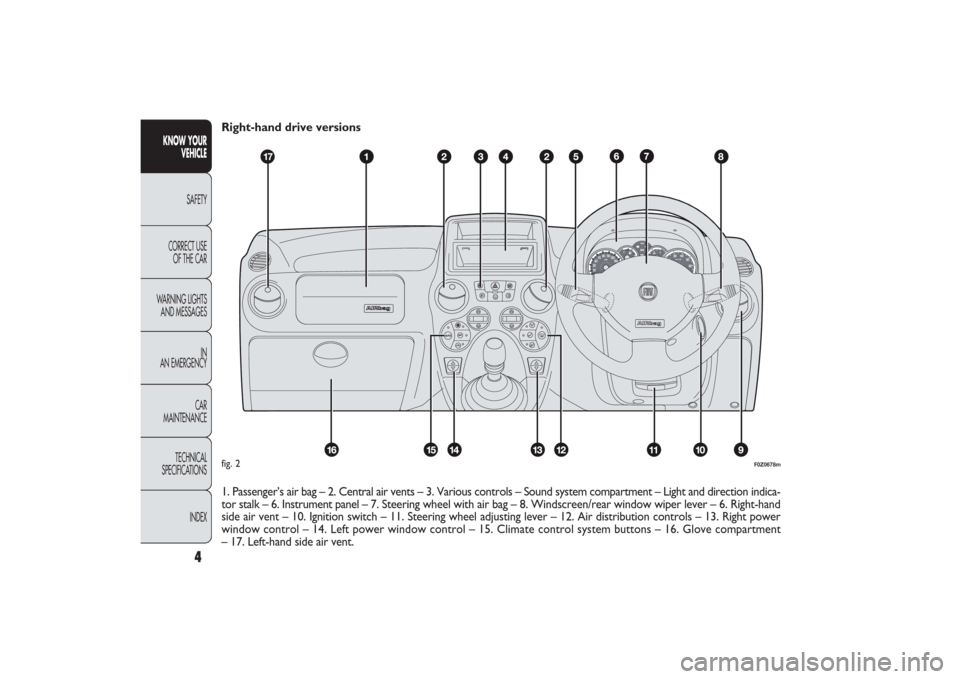
Right-hand drive versions
1. Passenger’s air bag – 2. Central air vents – 3. Various controls – Sound system compartment – Light and direction indica-
tor stalk – 6. Instrument panel – 7. Steering wheel with air bag – 8. Windscreen/rear window wiper lever – 6. Right-hand
side air vent – 10. Ignition switch – 11. Steering wheel adjusting lever – 12. Air distribution controls – 13. Right power
window control – 14. Left power window control – 15. Climate control system buttons – 16. Glove compartment
– 17. Left-hand side air vent.
CH
F
E
F0Z0678m
fig. 2
001-030 PANDA EN 7-10-2009 13:39 Pagina 4
Page 35 of 226

F0Z0034m
fig. 35
F0Z0061m
fig. 36
STEERING WHEELThe steering wheel can be adjusted in height
(for versions/markets where provided).
Release the lever A-fig. 36 pulling it towards the steering
wheel, then adjust it in the most suitable position
and lock it pushing the lever A fully forwards. REAR fig. 35
Depending on the versions, head restraints can be fixed
(for 5-seat versions) or adjustable. To use adjustable head
restraints, raise the head restraint from position 2 (posi-
tion of non use) to position 1 (completely raised).
To bring them back to the original “position of non use”,
press the button B and push the head restraint down.
To take them out, press both buttons B and C, raise them
completely.
The particular head restraint shape deliberately interferes
with the correct passenger’s back leaning on the back-
rest in order to force him/her to lift the head restraint
and use it correctly.
IMPORTANT If the rear seats are used, always set the
head restraints in the “completely raised” position.
34
KNOW YOUR
VEHICLE
SAFETY
CORRECT USE
OF THE CAR
WARNING LIGHTS
AND MESSAGES
IN
AN EMERGENCY
CAR
MAINTENANCE
TECHNICAL
SPECIFICATIONS
INDEX
Any adjustments must be carried out on-
ly with the car stationary and engine off.
WARNING
031-064 PANDA EN 7-10-2009 13:43 Pagina 34
Page 51 of 226

,
F0Z0127m
fig. 50
WINDOW WASHINGThe right stalk fig. 50 controls windscreen wiper/washer
and rear window wiper/washer operation.
WINDSCREEN WASHER/WIPER
The device can only work when the ignition key is at MAR.
The stalk has five different positions (four speed levels):
A windscreen wiper off.
B intermittent operation.
C continuous slow operation.
D continuous fast operation.
E fast temporary operation (spring-return position).
The temporary fast function lasts as long as you manually
keep the stalk in that position. The stalk returns to
position A when it is released, automatically stopping
the windscreen wipers.
50
KNOW YOUR
VEHICLE
SAFETY
CORRECT USE
OF THE CAR
WARNING LIGHTS
AND MESSAGES
IN
AN EMERGENCY
CAR
MAINTENANCE
TECHNICAL
SPECIFICATIONS
INDEX
Windscreen wiper slowing down according
to car speed
(for versions/markets where provided)
On some versions, when decelerating until stopping the
car, will the windscreen wiper will slow down automati-
cally. Speed will be resumed automatically when the car
speed exceeds 10 km/h. The windscreen speed can be
changed manually at any time.
“Smart washing” function
Pull the stalk towards the steering wheel (spring-return
position) to operate the windscreen washer.
Keep the stalk pulled, with just one movement, to operate
the washer jet and the windscreen wiper; the latter auto-
matically turns on if you keep the stalk pulled for more than
half a second. The windscreen wiper stops operating a few
strokes after releasing the stalk; a further “cleaning stroke”,
after a few seconds, completes the wiping operation.
Never use the windscreen wipers to remove
layers of snow or ice from the windscreen.
In these conditions, the windscreen wipers
may be submitted to excessive effort resulting in
motor protection cutting in and wiper operation in-
hibition for a few seconds. If the operation is not
restored, contact a Fiat Dealership.
031-064 PANDA EN 7-10-2009 13:43 Pagina 50
Page 75 of 226

When the ABS cuts in and you feel the
brake pedal pulsating, do not raise foot,
but keep it pressed; in doing so you will stop in the
shortest amount of space possible depending on
the current road conditions.
WARNING
If the ABS system cuts in, it means that the
grip between the tyre and the road surface
is close to its limit: you must slow down to match
the speed to the road grip available.
WARNING
The ABS make the best use of the avail-
able grip but cannot increase it. You
should always drive carefully on slippery surfaces
and avoid any unnecessary risks.
WARNING
ABS SYSTEM (for versions/markets, where provided)
This system, which is an integral part of the braking sys-
tem, prevents one or more wheels from locking and slip-
ping in all road surface conditions, irrespective of the
intensity of the braking action, ensuring that the vehicle can
be controlled even during emergency braking.
The EBD system (Electronic Braking Force Distribution)
completes the system allowing the brake force to be dis-
tributed between the front and rear wheels.
IMPORTANT To get the maximum efficiency of the brak-
ing system, a bedding-in period of about 500 km is need-
ed: during this period it is better to avoid sharp, repeat-
ed and prolonged braking.
SYSTEM INTERVENTION
The driver can feel the ABS system has come into action
because the brake pedal pulsates slightly and the system gets
noisier: it means that the car speed should be altered to suit
the type of road surface.
74
KNOW YOUR
VEHICLE
SAFETY
CORRECT USE
OF THE CAR
WARNING LIGHTS
AND MESSAGES
IN
AN EMERGENCY
CAR
MAINTENANCE
TECHNICAL
SPECIFICATIONS
INDEX
065-090 PANDA EN 7-10-2009 13:45 Pagina 74
Page 76 of 226

If only the
x
warning light on the instru-
ment panel lights up – together with
a message in the reconfigurable multifunction dis-
play (for versions/markets, where provided) – stop
the car immediately and contact the nearest
Fiat Dealership. Leakage of hydraulic fluid from
the braking system will compromise the operation
of the braking system, whether it is of the con-
ventional type or with ABS.WARNING
FAILURE WARNING
ABS failure fig. 86
It is indicated by the
>
warning light on the instrument
panel - together with the dedicated message in the re-
configurable multifunction display (for versions/markets,
where provided) - coming on (see “Warning lights
and messages” chapter).
In this case, the braking system will still be effective, al-
though without the extra capacity offered by the ABS sys-
tem. Drive carefully to the nearest Fiat Dealership to have
the system checked.
EBD failure fig. 87
It is indicated by the
>
and
x
warning lights on the in-
strument panel - together with the dedicated message
in the multifunction display (for versions/markets, where
provided) - coming on (see “Warning lights and messages”
chapter).In this case, the rear wheels may suddenly lock and the ve-
hicle may swerve when braking sharply. Drive carefully
to the nearest Fiat Dealership to have the system checked.
fig. 87
F0Z0159m
fig. 86
F0Z0158m
75KNOW YOUR
VEHICLESAFETY
CORRECT USE
OF THE CAR
WARNING LIGHTS
AND MESSAGES
IN
AN EMERGENCY
CAR
MAINTENANCE
TECHNICAL
SPECIFICATIONS
INDEX
065-090 PANDA EN 7-10-2009 13:45 Pagina 75
Page 105 of 226

104
KNOW YOUR
VEHICLE
SAFETY
CORRECT USE
OF THE CAR
WARNING LIGHTS
AND MESSAGES
IN AN EMERGENCY
CAR
MAINTENANCE
TECHNICAL
SPECIFICATIONS
INDEX
AIR BAGThe car is fitted with front air bags (for versions/markets
where provided) for the driver and the passenger and front
side bags (side bag – window bag).
FRONT AIR BAGS
The front driver/passenger air bags have been designed to
protect the occupants in the event of head-on crashes of
medium-high severity, by placing the cushion between the
occupant and the steering wheel or dashboard.
Front air bags are designed to protect car’s passengers in
head-on crashes and therefore non-activation in other
types of collisions (side collisions, rear shunts, roll-overs,
etc.) is not a system malfunction.
An electronic control unit will make the bag inflate in the
event of a front crash.
The bag will inflate instantaneously placing itself between
the front passengers’ body and the structures which could
cause injury. It will deflate immediately afterwards.
Driver and passenger front airbags are not a replacement
of but complementary to the seat belts, which should al-
ways be worn, as specified by law in Europe and most non-
European countries.
In the event of an impact, those not wearing a seat belt will
move forward and come into contact with the bag which
is still inflating. The protection offered by the air bag cush-
ion is reduced in such a case.Front air bags may not be activated in the following situ-
ations:
❒
in collisions against highly deformable objects not af-
fecting the car front surface (e.g. bumper collision against
guard rail, etc.);
❒
car wedging under other vehicles or protective barri-
ers (e.g. trucks or guard rails);
they could not provide any additional protection compared
with seat belts, so their activation would be improper.
Therefore, failure to come into action in the above cir-
cumstances does not mean that the system is not work-
ing properly.
Do not apply stickers or other objects to
the steering wheel, to the passenger’s side
air bag cover side or on the side roof lining. Nev-
er put objects (e.g. mobile phones) on the pas-
senger’s side dashboard since they could interfere
with proper air bag inflation and also cause seri-
ous injury to the passengers.
WARNING
091-110 PANDA EN 7-10-2009 13:46 Pagina 104
Page 120 of 226

119KNOW
YOUR VEHICLE
SAFETYCORRECT USE
OF THE CARWARNING LIGHTS
AND MESSAGES
IN
AN EMERGENCY
CAR
MAINTENANCE
TECHNICAL
SPECIFICATIONS
INDEX
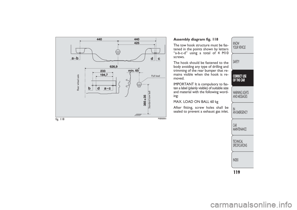
Assembly diagram fig. 118
The tow hook structure must be fas-
tened in the points shown by letters
“a-b-c-d” using a total of 4 M10
screws.
The hook should be fastened to the
body avoiding any type of drilling and
trimming of the rear bumper that re-
mains visible when the hook is re-
moved.
IMPORTANT It is compulsory to fas-
ten a label (plainly visible) of suitable size
and material with the following word-
ing:
MAX. LOAD ON BALL 60 kg
After fitting, screw holes shall be
sealed to prevent a exhaust gas inlet.
fig. 118
F0Z0225m
Rear wheel axle
Standard tow ball
Full load
111-122 PANDA EN 7-10-2009 15:01 Pagina 119