2009 FIAT DUCATO load
[x] Cancel search: loadPage 89 of 282

88
SAFETY
DEVICES
CORRECT USE
OF THE
VEHICLE
WARNING
LIGHTS AND
MESSAGES
IN AN
EMERGENCY
VEHICLE
MAINTENANCE
TECHNICAL
SPECIFICATIONS
INDEX
DASHBOARD
AND CONTROLS
fig. 97F0N0056m
fig. 98F0N0057m
SUN VISORS fig. 97
These are positioned to the sides of the
rear-view mirror. They can swing to the
sides and up or down.
CURRENT OUTLET
(where provided)
It is located on the central panel, near the
cigar lighter fig. 98.
To use it open cap A.WRITING/READING DESK
(where provided)
In the middle of the dashboard, above the
sound system compartment, is fitted a
writing desk A-fig. 99that, on certain ver-
sions can be used as a reading desk by lift-
ing its rear part and then resting it on the
dashboard as shown in the figure.
On versions fitted with passenger's air bag,
the writing/reading desk is fix.STOWING SPACE ABOVE THE
CAB fig. 100 (where provided)
It is set above the driver's cab and it has
been designed to stow light items.
Max. admissible:
– localised load ...................................10 kg
– load distributed on the whole
shelf surface .....................................20 kg
fig. 99F0N0058mfig. 100F0N0190m
Never use the writing desk
in vertical position when
travelling.
WARNING
Page 91 of 282

90
SAFETY
DEVICES
CORRECT USE
OF THE
VEHICLE
WARNING
LIGHTS AND
MESSAGES
IN AN
EMERGENCY
VEHICLE
MAINTENANCE
TECHNICAL
SPECIFICATIONS
INDEX
DASHBOARD
AND CONTROLS
The display is provided with buttons
(On/Off, brightness, background bright-
ness). To use it, press the release button
and set the display to open position.
The rearview display is adjusted and ori-
ented like mirror and when it is not used
it shall be stowed into the top oddment
compartment.
ACTIVATION
The system activates with ignition key fit-
ted when engaging reverse or pressing the
relevant button. With reverse engaged
and vehicle moving, the system will work
up to a max. speed of about 15km/h and
it will deactivate if 18km/h speed is ex-
ceeded. Displayed image will stay on for
approx. 5 seconds after disengaging re-
verse. GENERAL DIRECTIONS
Visible range
The visible range varies according to ve-
hicle conditions (including full load con-
dition), vehicle characteristics and weath-
er conditions (daylight, rain, snow and fog);
with poor light or in full load conditions
the range of visibility may be reduced.
The camera covers a range of approx. 3
m length and approx. 5.5 m max. width
fig. 105.Instructions for use
To clean the camera use a soft cloth when
the protecting glass is dirty or frozen (out-
side). Never use other tools for cleaning
it to prevent scratching the glass.
To clean the display use also a dry soft
cloth. Dust can be removed using proper
brushes provided for the purpose. Nev-
er use detergents.
The display glass may break if blown. In
this event do not touch the leaking fluid.
Rinse immediately with water and soap in
case of accidental contact.
fig. 104F0N0214mfig. 105F0N0215m
Page 94 of 282

93
SAFETY
DEVICES
CORRECT USE
OF THE
VEHICLE
WARNING
LIGHTS AND
MESSAGES
IN AN
EMERGENCY
VEHICLE
MAINTENANCE
TECHNICAL
SPECIFICATIONS
INDEX
DASHBOARD
AND CONTROLS
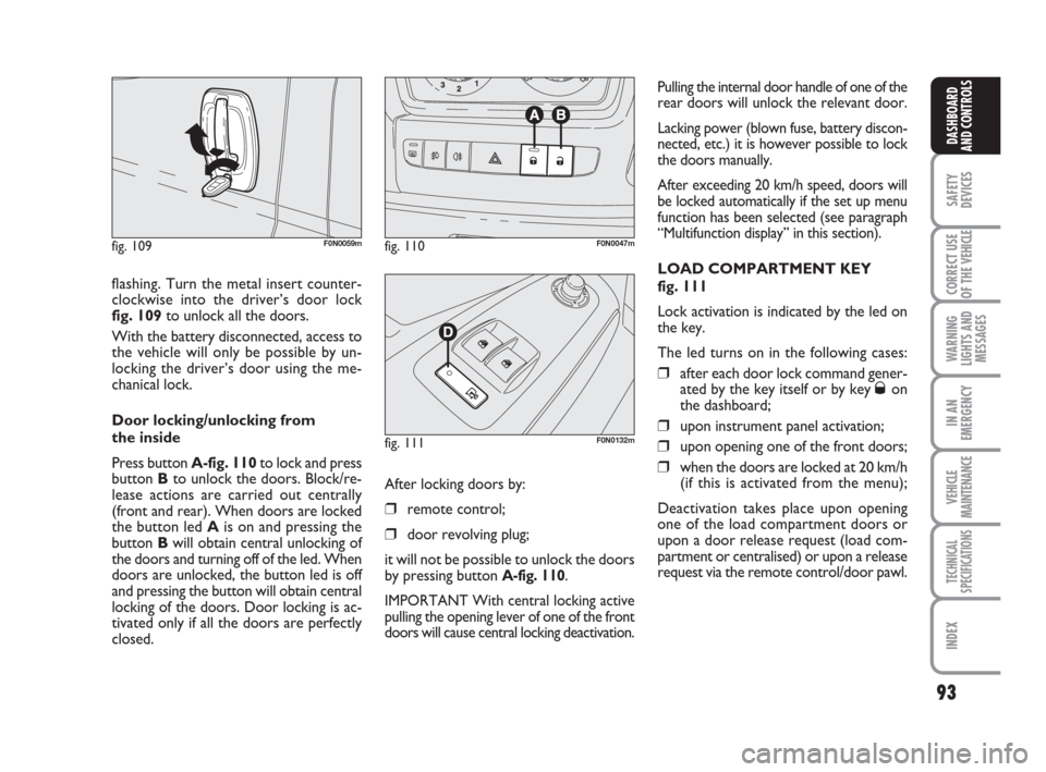
flashing. Turn the metal insert counter-
clockwise into the driver’s door lock
fig. 109to unlock all the doors.
With the battery disconnected, access to
the vehicle will only be possible by un-
locking the driver’s door using the me-
chanical lock.
Door locking/unlocking from
the inside
Press button A-fig. 110to lock and press
button Bto unlock the doors. Block/re-
lease actions are carried out centrally
(front and rear). When doors are locked
the button led Ais on and pressing the
button Bwill obtain central unlocking of
the doors and turning off of the led. When
doors are unlocked, the button led is off
and pressing the button will obtain central
locking of the doors. Door locking is ac-
tivated only if all the doors are perfectly
closed.
fig. 109F0N0059mfig. 110F0N0047m
fig. 111F0N0132m
Pulling the internal door handle of one of the
rear doors will unlock the relevant door.
Lacking power (blown fuse, battery discon-
nected, etc.) it is however possible to lock
the doors manually.
After exceeding 20 km/h speed, doors will
be locked automatically if the set up menu
function has been selected (see paragraph
“Multifunction display” in this section).
LOAD COMPARTMENT KEY
fig. 111
Lock activation is indicated by the led on
the key.
The led turns on in the following cases:
❒after each door lock command gener-
ated by the key itself or by key Øon
the dashboard;
❒upon instrument panel activation;
❒upon opening one of the front doors;
❒when the doors are locked at 20 km/h
(if this is activated from the menu);
Deactivation takes place upon opening
one of the load compartment doors or
upon a door release request (load com-
partment or centralised) or upon a release
request via the remote control/door pawl. After locking doors by:
❒remote control;
❒door revolving plug;
it will not be possible to unlock the doors
by pressing button
A-fig. 110.
IMPORTANT With central locking active
pulling the opening lever of one of the front
doors will cause central locking deactivation.
Page 96 of 282

95
SAFETY
DEVICES
CORRECT USE
OF THE
VEHICLE
WARNING
LIGHTS AND
MESSAGES
IN AN
EMERGENCY
VEHICLE
MAINTENANCE
TECHNICAL
SPECIFICATIONS
INDEX
DASHBOARD
AND CONTROLS
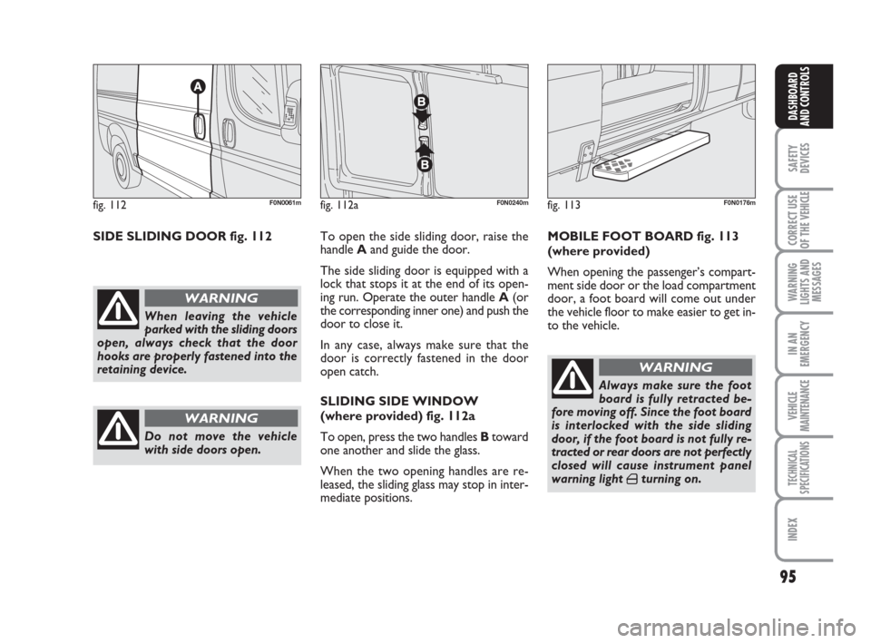
SIDE SLIDING DOOR fig. 112To open the side sliding door, raise the
handle Aand guide the door.
The side sliding door is equipped with a
lock that stops it at the end of its open-
ing run. Operate the outer handle A(or
the corresponding inner one) and push the
door to close it.
In any case, always make sure that the
door is correctly fastened in the door
open catch.
SLIDING SIDE WINDOW
(where provided) fig. 112a
To open, press the two handles Btoward
one another and slide the glass.
When the two opening handles are re-
leased, the sliding glass may stop in inter-
mediate positions.MOBILE FOOT BOARD fig. 113
(where provided)
When opening the passenger’s compart-
ment side door or the load compartment
door, a foot board will come out under
the vehicle floor to make easier to get in-
to the vehicle.
fig. 112F0N0061m
When leaving the vehicle
parked with the sliding doors
open, always check that the door
hooks are properly fastened into the
retaining device.
WARNING
Do not move the vehicle
with side doors open.
WARNING
Always make sure the foot
board is fully retracted be-
fore moving off. Since the foot board
is interlocked with the side sliding
door, if the foot board is not fully re-
tracted or rear doors are not perfectly
closed will cause instrument panel
warning light
´turning on.
WARNING
fig. 113F0N0176mfig. 112aF0N0240m
Page 98 of 282

97
SAFETY
DEVICES
CORRECT USE
OF THE
VEHICLE
WARNING
LIGHTS AND
MESSAGES
IN AN
EMERGENCY
VEHICLE
MAINTENANCE
TECHNICAL
SPECIFICATIONS
INDEX
DASHBOARD
AND CONTROLS
The spring catch system is
designed to ensure the best
comfort in use. An accidental knock
or gust of wind could release the
springs and make doors close.
WARNING
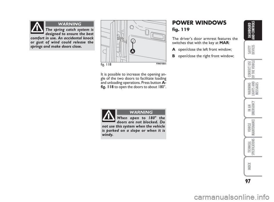
It is possible to increase the opening an-
gle of the two doors to facilitate loading
and unloading operations. Press button A-
fig. 118to open the doors to about 180°.
When open to 180° the
doors are not blocked. Do
not use this system when the vehicle
is parked on a slope or when it is
windy.
WARNING
fig. 118F0N0188m
POWER WINDOWS
fig. 119
The driver’s door armrest features the
switches that with the key at MAR:
Aopen/close the left front window;
Bopen/close the right front window;
Page 101 of 282

Distribute the load evenly
and when driving, bear in
mind the increased sensitivity of the
vehicle to side wind.
100
SAFETY
DEVICES
CORRECT USE
OF THE
VEHICLE
WARNING
LIGHTS AND
MESSAGES
IN AN
EMERGENCY
VEHICLE
MAINTENANCE
TECHNICAL
SPECIFICATIONS
INDEX
DASHBOARD
AND CONTROLS
ROOF RACK/SKI RACK
To fit roof racks/ski racks, with presetting
for versions H1 and H2, use the proper
pins set at roof edges fig. 124.
Long wheelbase vehicles are fitted with 8
pins; short or medium wheelbase vehicles
are fitted with 6 pins; extra-long wheel-
base vehicles are fitted with 10 pins.
After travelling a few kilo-
metres, check that the cou-
pling fastening screws are tight.
WARNING
Strictly comply with current
law regulations concerning
max. overall dimensions.
Never exceed the permitted
weight (see section “Techni-
cal specifications”).
IMPORTANT Strictly follow the installa-
tion instructions contained in the kit. In-
stallation hall be carried out by skilled per-
sonnel.
fig. 124F0N0138m
WARNING
Page 102 of 282

101
SAFETY
DEVICES
CORRECT USE
OF THE
VEHICLE
WARNING
LIGHTS AND
MESSAGES
IN AN
EMERGENCY
VEHICLE
MAINTENANCE
TECHNICAL
SPECIFICATIONS
INDEX
DASHBOARD
AND CONTROLS
HEADLIGHTS
ADJUSTING THE HEADLIGHT
BEAM
Proper adjustment of the headlight beams
is of vital importance for your safety and
comfort and also for the other road users.
To ensure you and other drivers have the
best visibility conditions when travelling
with the headlights on, the headlights must
be set properly. Contact Fiat Dealership
to have the headlights properly adjusted.
fig. 125F0N0067m
HEADLIGHT AIMING DEVICE
It works with ignition key at MARand
dipped beams on. When the vehicle is
loaded, it slopes backwards. This means
that the headlight beam rises. In this case,
it is necessary to return it to the correct
position.To adjust the headlight slant
fig. 125
Press buttons Òand set on the con-
trol panel.
The display located on the instrument pan-
el, provides the visual indication of the po-
sitions during the adjustment operation.
IMPORTANT Check beam aiming every
time the load carried changes.
ADJUSTING THE FRONT FOG
LIGHTS (where provided)
Contact Fiat Dealership to have the head-
lights properly adjusted.
HEADLIGHT ADJUSTMENT
ABROAD
The dipped beam headlights are adjusted
for circulation in the country in which the
vehicle is marketed. In countries with op-
posite circulation, to avoid glaring on-
coming vehicles, it is necessary to cover
the areas of the headlight using a special
sticker tape provided for the purpose.
Page 106 of 282

105
SAFETY
DEVICES
CORRECT USE
OF THE
VEHICLE
WARNING
LIGHTS AND
MESSAGES
IN AN
EMERGENCY
VEHICLE
MAINTENANCE
TECHNICAL
SPECIFICATIONS
INDEX
DASHBOARD
AND CONTROLS
MSR system
(engine braking torque control)
It is an integral part of the ASR system that
in case of sudden gear shifting, cuts in pro-
viding torque to the engine thus prevent-
ing excessive driving wheel drive that, spe-
cially in poor grip conditions, can lead to
loss of stability.
Switching the systemon/off fig. 126
The ASR system switches on automatically
each time the engine is started.
When travelling, the ASR can be switched
off and on again by pressing switch Alo-
cated on the dashboard fig. 126. When the ASR is switched off this is
shown by the lighting up of the led on the
switch and by relevant message on the
multifunction display, where provided.
Versions equipped with ASR system on-
ly, at deactivation (ASR OFF) the warn-
ing light Vwill always stay on.
If the ASR is switched off when travelling,
it will turn on again automatically the next
time the engine is started.
When travelling on snowy roads with
snow chains, it may be helpful to turn the
ASR off: in fact, in these conditions, slip-
ping of the driving wheels when moving off
makes it possible to obtain better drive.
For correct operation of the
ESP and ASR systems, the
tyres must absolutely be of the same
brand and type on all wheels, in per-
fect conditions and, above all, of
type, brand and size specified.
WARNING
fig. 126F0N0077m
ASR SYSTEM (Antislip Regulator)
The ASR function controls vehicle drive
and cuts in automatically every time one
or both driving wheels slip.
According to slipping conditions, two dif-
ferent control systems are activated:
❒if slipping involves both driving wheels,
the ASR function intervenes reducing
the power transmitted by the engine;
❒if the slipping involves only one dri-
ving wheel, the ASR system cuts in au-
tomatically braking the wheel that is
slipping.
The action of the ASR is particularly help-
ful in the following circumstances:
❒slipping of the inner wheel due to the
effect of dynamic load changes or ex-
cessive acceleration;
❒too much power transmitted to the
wheels also in relation to the condi-
tions of the road surface;
❒acceleration on slippery, snowy or
frozen surfaces;
❒in the case of loss of grip on a wet sur-
face (aquaplaning).