2009 DODGE RAM 3500 DIESEL warning light
[x] Cancel search: warning lightPage 372 of 532
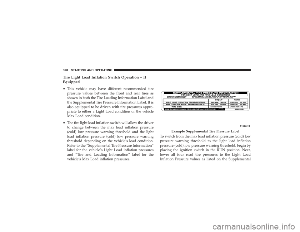
Tire Light Load Inflation Switch Operation – If
Equipped
•
This vehicle may have different recommended tire
pressure values between the front and rear tires as
shown in both the Tire Loading Information Label and
the Supplemental Tire Pressure Information Label. It is
also equipped to be driven with tire pressures appro-
priate to either a Light Load condition or the vehicle
Max Load condition.
•
The tire light load inflation switch will allow the driver
to change between the max load inflation pressure
(cold) low pressure warning threshold and the light
load inflation pressure (cold) low pressure warning
threshold depending on the vehicle’s load condition.
Refer to the “Supplemental Tire Pressure Information”
label for the vehicle’s Light Load inflation pressures
and “Tire and Loading Information” label for the
vehicle’s Max Load inflation pressures.To switch from the max load inflation pressure (cold) low
pressure warning threshold to the light load inflation
pressure (cold) low pressure warning threshold, begin by
placing the ignition switch in the RUN position. Next,
lower all four road tire pressures to the Light Load
Inflation Pressure values as listed on the Supplemental
Example Supplemental Tire Pressure Label
370 STARTING AND OPERATING
Page 373 of 532
Tire Pressure Information label. The Supplemental Tire
Pressure Information label is located on the rear face of
the driver door. Use an accurate tire gauge to check the
tire pressures when lowering all four tire pressures. After
all four tire pressures have been lowered to the Light
Load inflation pressures, press the tire light load inflation
switch. If the tire light load inflation switch’s amber
colored LED turns ON, the TPMS is using the light load
inflation pressure (cold) low pressure warning thresh-
olds.
If the tire light load inflation switch amber colored LED
flashes on and off for 10 seconds, after all four tire
pressures have been lowered to the Light Load inflation
pressures, the pressure in any one of the four tires may
not be at the light load inflation pressure (cold) values as
indicated for the Light Load condition as defined on the
Supplemental Tire Pressure Information label located onthe rear face of the driver door. Using an accurate tire
pressure gauge, re-check the tire pressures for the light
load inflation pressure (cold) value.
WARNING!
It is the driver ’s responsibility to change to the max
load inflation pressure (cold) low pressure warning
threshold condition when not driving in the light
load condition as defined as two occupants (150 lbs
[68 kg] each) plus 200 pounds (91 kg) of cargo. The
vehicle “Light Load Definition” is found in the
Supplemental Tire Pressure Information label lo-
cated on the rear face of the driver door. Failure to do
so may cause you to lose control resulting in an
accident, causing serious or fatal injury.
To switch back to the max load inflation pressure (cold)
low pressure warning threshold, press the tire light load
inflation switch. It is not necessary to first fill the tires to
STARTING AND OPERATING 371
5
Page 374 of 532

the max load inflation pressure (cold) values to switch
the TPMS system to the max load inflation pressure
(cold) low pressure warning threshold. If after pressing
the tire light load inflation switch, and tire pressures are
below the max load inflation pressure (cold) low pressure
warning thresholds, the TPMS low pressure warning
telltale light (located in the instrument cluster) will turn
ON and a chime will sound. The tire pressures are now
required to be inflated to the max load inflation pressure
(cold) values described on the Tire and Loading Informa-
tion label. The Tire and Loading Information label is
located on the drivers side B-pillar. If the tire light load
inflation switch LED turns OFF, the TPMS has been reset
and the TPMS is using the max load inflation pressure
(cold) low pressure warning thresholds.Tire Pressure Monitor System ComponentsThe Tire Pressure Monitor System (TPMS) uses wireless
technology with wheel rim mounted electronic sensors tomonitor tire pressure levels. Sensors, mounted to each
wheel as part of the valve stem, transmit tire pressure
readings to the Receiver Module.
NOTE:
It is particularly important, for you to check the
tire pressure in all of your tires regularly and to maintain
the proper pressure.
The Tire Pressure Monitoring System (TPMS) consists of
the following components:
•
Receiver Module
•
Four Wheel Sensors
•
Two Trigger Modules (mounted in the front wheel-
wells)
•
Tire Light Load Inflation Switch (located in the instru-
ment panel)
•
Tire Pressure Monitoring Telltale Light
372 STARTING AND OPERATING
Page 375 of 532

Tire Pressure Monitoring Low Pressure Warnings
The “Tire Pressure Monitoring Telltale Light” will
illuminate in the instrument cluster, and an au-
dible chime will be activated when one or more of
the four active road tire pressures are low. Should this
occur, you should stop as soon as possible, check the
inflation pressure of each tire on your vehicle and inflate
each tire to the vehicle’s recommended cold placard
pressure value. The system will automatically update
and the “Tire Pressure Monitoring Telltale Light” will
extinguish once the updated tire pressures have been
received. The vehicle may need to be driven for up to
20 minutes above 15 mph (25 km/h) to receive this
information.
Check TPMS WarningsThe “Tire Pressure Monitoring Telltale Light” (located in
the instrument cluster) will flash on and off for 75 sec-
onds and will remain on solid when a system fault is
detected. The system fault will also sound a chime. If the ignition key is cycled, this sequence will repeat, provid-
ing the system fault still exists. A system fault can occur
by any of the following scenarios:
1. Signal interference due to electronic devices or driving
next to facilities emitting the same Radio Frequencies as
the TPM sensors.
2. Installing aftermarket window tinting that affects ra-
dio wave signals.
3. Accumulation of snow or ice around the wheels or
wheel housings.
4. Using tire chains on the vehicle.
5. Using wheels/tires not equipped with TPM sensors.
6. Loss of communication with the trigger modules or
tire pressure monitoring sensors.
NOTE: Your vehicle is equipped with a non-matching
full size spare wheel and tire assembly.
STARTING AND OPERATING 373
5
Page 376 of 532

1. This spare tire does not have a tire pressure monitor-
ing sensor. Therefore, the TPMS will not monitor the tire
pressure in the spare tire.
2. If you install the full size spare tire in place of a road
tire that has a pressure below the low-pressure warning
limit, upon the next ignition key cycle, a chime will
sound and the “TPM Telltale Light” will still turn ON
due to the low tire.
3. However, after driving the vehicle for up to 20 min-
utes above 15 mph (25 km/h), the “TPM Telltale Light”
will flash on and off for 75 seconds and then remain on
solid.
4. For each subsequent ignition key cycle, a chime will
sound and the “TPM Telltale Light” will flash on and off
for 75 seconds and then remain on solid.5. Once you repair or replace the original road tire, and
reinstall it on the vehicle in place of the full size spare tire,
the TPMS will update automatically and the “TPM
Telltale Light” will turn OFF, as long as no tire pressure is
below the low-pressure warning limit in any of the four
active road tires. The vehicle may need to be driven for
up to 20 minutes above 15 mph (25 km/h) in order for the
TPMS to receive this information.
General InformationThis device complies with part 15 of the FCC rules and
RSS 210 of Industry Canada. Operation is subject to the
following conditions:•
This device may not cause harmful interference.
•
This device must accept any interference received,
including interference that may cause undesired
operation.
374 STARTING AND OPERATING
Page 381 of 532
Carbon Monoxide Warnings
WARNING!
Carbon monoxide (CO) in exhaust gases is deadly.
Follow the precautions below to prevent carbon
monoxide poisoning:•
Do not inhale exhaust gases. They contain carbon
monoxide, a colorless and odorless gas which can kill.
Never run the engine in a closed area, such as a
garage, and never sit in a parked vehicle with the
engine running for an extended period. If the vehicle is
stopped in an open area with the engine running for
more than a short period, adjust the ventilation system
to force fresh, outside air into the vehicle.
•
Guard against carbon monoxide with proper mainte-
nance. Have the exhaust system inspected every timethe vehicle is raised. Have any abnormal conditions
repaired promptly. Until repaired, drive with all side
windows fully open.
ADDING FUELThe fuel tank filler tube has a restricting door about 2 in
(50 mm) inside the opening. If using a portable fuel
container, it should have a flexible nozzle long enough to
force open the restricting door.
CAUTION!
•
Damage to the fuel system or emissions control
system could result from using an improper fuel
tank filler tube cap (gas cap). A poorly fitting cap
could let impurities into the fuel system. Also, a
poorly-fitted aftermarket cap can cause the MIL
(Malfunction Indicator Light) to illuminate due to
fuel vapors escaping from the system.
(Continued)
STARTING AND OPERATING 379
5
Page 382 of 532
CAUTION! (Continued)
•
A poorly fitting gas cap may cause the MIL to turn
on.
•
To avoid fuel spillage and overfilling, do not “top
off” the fuel tank after filling.
NOTE: When the fuel nozzle “clicks” or shuts off the
fuel tank is full.
WARNING!
•
Never have any smoking materials lit in or near
the vehicle when the gas cap is removed or the
tank filled.
•
Never add fuel to the vehicle when the engine is
running. This is in violation of most state and
federal fire regulations and will cause the MIL to
turn on. NOTE:
Tighten the gas cap 1/4 turn until you hear one
click. This is an indication that the cap is properly
tightened.
If the gas cap is not tightened properly, the Malfunction
Indicator Light will come on, Be sure the gas cap is
tightened every time the vehicle is refueled.
WARNING!
A fire may result if gasoline is pumped into a
portable container that is inside of a vehicle. You
could be burned. Always place gas containers on the
ground while filling.
380 STARTING AND OPERATING
Page 395 of 532
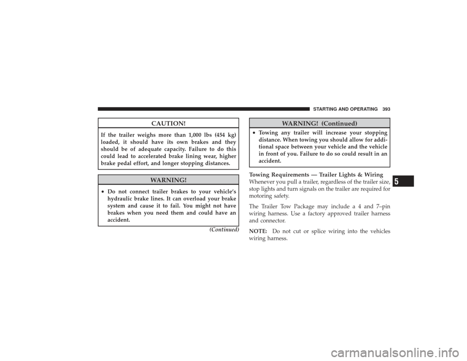
CAUTION!
If the trailer weighs more than 1,000 lbs (454 kg)
loaded, it should have its own brakes and they
should be of adequate capacity. Failure to do this
could lead to accelerated brake lining wear, higher
brake pedal effort, and longer stopping distances.
WARNING!
•
Do not connect trailer brakes to your vehicle’s
hydraulic brake lines. It can overload your brake
system and cause it to fail. You might not have
brakes when you need them and could have an
accident.(Continued)
WARNING! (Continued)
•
Towing any trailer will increase your stopping
distance. When towing you should allow for addi-
tional space between your vehicle and the vehicle
in front of you. Failure to do so could result in an
accident.
Towing Requirements — Trailer Lights & WiringWhenever you pull a trailer, regardless of the trailer size,
stop lights and turn signals on the trailer are required for
motoring safety.
The Trailer Tow Package may include a 4 and 7–pin
wiring harness. Use a factory approved trailer harness
and connector.
NOTE:Do not cut or splice wiring into the vehicles
wiring harness.
STARTING AND OPERATING 393
5