Page 402 of 532

CAUTION!
•
Do not use a bumper-mounted clamp-on tow bar
on your vehicle. The bumper face bar will be
damaged.
•
Do not disconnect the rear driveshaft because
fluid will leak from the transfer case and damage
the internal parts.
Recreational Towing Procedure — Electronic Shift
Transfer Case — If EquippedUse the following procedure to prepare your vehicle for
recreational towing:
CAUTION!
It is necessary to follow these steps to be certain that
the transfer case is fully in NEUTRAL before recre-
ational towing, to prevent damage to internal parts.1. Bring the vehicle to a complete stop.
2. Shut OFF the engine.
3. Turn the ignition key to the ON position, but do not
start the engine.
4. Depress the brake pedal.
5. Shift the transmission into NEUTRAL.
6. Using the point of a ballpoint pen or similar object,
depress the recessed transfer case NEUTRAL button for
four seconds.
7. After shift is completed and the NEUTRAL light
comes on, release the NEUTRAL button.
8. Start the engine.
9. Shift the transmission into REVERSE.
10. Release the brake pedal for five seconds and ensure
that there is no vehicle movement.400 STARTING AND OPERATING
Page 405 of 532

•
The ignition key must be ON for a transfer case shift to
take place and for the position indicator lights to be
operable. If the key is not ON, the shift will not take
place and no position indicator lights will be on or
flashing.
•
Flashing Neutral position indicator light indicates that
shift requirements have not been met.
WARNING!
You or others could be injured if you leave the
vehicle unattended with the transfer case in the
NEUTRAL position without first fully engaging the
parking brake. The transfer case NEUTRAL position
disengages both the front and rear driveshafts from
the powertrain and will allow the vehicle to move
despite the transmission position. The parking brake
should always be applied when the driver is not in
the vehicle.
CAUTION!
•
Do not use a bumper-mounted clamp-on tow bar
on your vehicle. The bumper face bar will be
damaged.
•
Do not disconnect the rear driveshaft because
fluid will leak from the transfer case and fluid loss
will damage internal parts.
EQUIPMENT IDENTIFICATION PLATEThe equipment Identification Plate is located on the hood
inner surface.
The following information about your vehicle is dis-
played on this plate: Model, Wheelbase, Vehicle Identifi-
cation Number, Truck Order Number, and code numbers
with descriptions of all production and special equip-
ment on the truck as shipped from the factory.
NOTE:Always refer to the Equipment Identification
Plate When Ordering Parts.
STARTING AND OPERATING 403
5
Page 428 of 532

▫Cooling System .................... 441
▫ Brake System ...................... 447
▫ Rear Axle And 4X4 Front Driving Axle Fluid
Level ............................. 448
▫ Transfer Case ...................... 449
▫ Automatic Transmission .............. 449
▫ Appearance Care And Protection From
Corrosion .......................... 452
� Fuses ............................. 458
▫ Integrated Power Module ............. 458
� Vehicle Storage ...................... 463
� Replacement Light Bulbs ............... 464
� Bulb Replacement .................... 465
▫ Headlight (Halogen)/Front Park And Turn
Lights ............................ 465 ▫
Fog Lights ........................ 468
▫ Tail, Stop, Turn And Backup Lights ...... 469
▫ Center High-Mounted Stoplight (CHMSL)
With Cargo Light .................... 472
▫ Cab Top Clearance Lights — If Equipped . . 473
▫ Tailgate ID Lights (Dual Rear Wheels) —
If Equipped ........................ 475
▫ Rear Light Bar ID Marker
(Dual Rear Wheel) — If Equipped ........ 476
▫ Side Marker Lights (Dual Rear Wheels) . . . 477
� Fluids And Capacities ................. 478
� Fluids, Lubricants And Genuine Parts ...... 479
▫ Engine ........................... 479
▫ Chassis .......................... 480
426 MAINTAINING YOUR VEHICLE
Page 429 of 532
ENGINE COMPARTMENT— 5.7L1 — Air Cleaner Filter7 — Power Steering Fluid Reservoir
2 — Automatic Transmission Dipstick 8 — Engine Oil Dipstick
3 — Engine Oil Fill 9 — Washer Fluid Reservoir
4 — Brake Fluid Reservoir 10 — Engine Coolant Reservoir
5 — Battery 11 — Coolant Pressure Cap
6 — Integrated Power Module MAINTAINING YOUR VEHICLE 427
7
Page 449 of 532

•
Do not change the thermostat for Summer or Winter
operation. If replacement is ever necessary, install
ONLY the correct type thermostat. Other designs may
result in unsatisfactory coolant performance, poor gas
mileage, and increased emissions.
Brake System
Master Cylinder — Brake Fluid Level CheckThe fluid level of the master cylinder should be checked
when performing under the hood service, or immedi-
ately if the brake system warning lamp indicates system
failure.
The brake master cylinder has a translucent plastic
reservoir. On the outboard side of the reservoir, there is a
“FULL” mark and an “ADD” mark. The fluid level must
be kept within these two marks. Do not add fluid above
the “FULL” mark, because leakage may occur at the cap.With disc brakes the fluid level can be expected to fall as
the brake linings wear. However, an unexpected drop in
fluid level may be caused by a leak and a system check
should be conducted.
Refer to “Fluids, Lubricants, and Genuine Parts” in this
section for the correct fluid type.
WARNING!
•
Use of a brake fluid that may have a lower initial
boiling point, or is unidentified as to specification,
may result in sudden brake failure during hard
prolonged braking. You could have an accident.
•
Overfilling the brake fluid reservoir can result in
spilling brake fluid on hot engine parts and the
brake fluid catching fire.
(Continued)
MAINTAINING YOUR VEHICLE 447
7
Page 450 of 532

•
Use only brake fluid that has been in a tightly-
closed container to avoid contamination from for-
eign matter or moisture.
CAUTION!
Do not allow a petroleum-base fluid to con")
WARNING! (Continued)
•
Use only brake fluid that has been in a tightly-
closed container to avoid contamination from for-
eign matter or moisture.
CAUTION!
Do not allow a petroleum-base fluid to contaminate
the brake fluid. Seal damage may result.Rear Axle And 4x4 Front Driving Axle Fluid LevelFor normal service, periodic fluid level checks are not
required. When the vehicle is serviced for other reasons
the exterior surfaces of the axle assembly should be
inspected. If gear oil leakage is suspected inspect the
fluid level. Refer to “Fluids, Lubricants, and Genuine
Parts” in this section for the correct fluid type.This inspection should be made with the vehicle in a level
position. The fluid level should be even with the bottom
of the fill hole for the manufacturer’s C205F HD front
axles. The fluid level should be 5/8 in (16 mm) below the
fill hole on 9 1/4 in manufacturer’s rear axles.
For all 2500/3500 Model axles, the fluid level should be
1/4” ± 1/4 in (6.4 mm ± 6.4 mm) below the fill hole on
the 9.25 in front and 3/4 in ± 1/4 in (19 mm ± 6.4 mm) on
10.5 in rear axles. The 11.5 in rear axle level should be
1/4 in ± 1/4 in (6.4 mm ± 6.4 mm) below the fill hole.
Drain and RefillRefer to the “Maintenance Schedule” in Section 8 for the
proper maintenance intervals.Lubricant SelectionRefer to “Fluids, Lubricants, and Genuine Parts” in this
section for the correct fluid type.
448 MAINTAINING YOUR VEHICLE
Page 453 of 532

3. Fully apply the parking brake and press the brake
pedal.
4. Place the shift lever momentarily into each gear posi-
tion ending with the lever in PARK.
5. Remove the dipstick, wipe it clean and reinsert it until
seated.
6. Remove the dipstick again and note the fluid level on
both sides. The fluid level should be between the “HOT”
(upper) reference holes on the dipstick at normal operat-
ing temperature. Verify that solid coating of oil is seen on
both sides of the dipstick. If the fluid is low, add as
required into the dipstick tube.Do not overfill.After
adding any quantity of oil through the oil fill tube, wait
a minimum of two minutes for the oil to fully drain into
the transmission before rechecking the fluid level.
NOTE: If it is necessary to check the transmission below
the operating temperature, the fluid level should be between the two “COLD” (lower) holes on the dipstick
with the fluid at approximately 70°F (21°C) (room tem-
perature). If the fluid level is correctly established at
room temperature, it should be between the “HOT”
(upper) reference holes when the transmission reaches
180°F (82°C). Remember it is best to check the level at the
normal operating temperature.
CAUTION!
Be aware that if the fluid temperature is below 50°F
(10°C) it may not register on the dipstick. Do not add
fluid until the temperature is elevated enough to
produce an accurate reading.
7. Check for leaks. Release parking brake.
To prevent dirt and water from entering the transmission
after checking or replenishing fluid, make certain that the
dipstick cap is properly reseated. It is normal for the
MAINTAINING YOUR VEHICLE 451
7
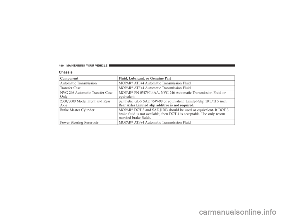
Page 482 of 532
ChassisComponentFluid, Lubricant, or Genuine Part
Automatic Transmission MOPAR�ATF+4 Automatic Transmission Fluid
Transfer Case MOPAR�ATF+4 Automatic Transmission Fluid
NVG 246 Automatic Transfer Case
Only MOPAR�
PN 05179014AA, NVG 246 Automatic Transmission Fluid or
equivalent
2500/3500 Model Front and Rear
Axle Synthetic, GL-5 SAE, 75W-90 or equivalent. Limited-Slip 10.5/11.5 inch
Rear Axles
Limited slip additive is not required.
Brake Master Cylinder MOPAR�DOT 3 and SAE J1703 should be used or equivalent. If DOT 3
brake fluid is not available, then DOT 4 is acceptable. Use only recom-
mended brake fluids.
Power Steering Reservoir MOPAR�ATF+4 Automatic Transmission Fluid480 MAINTAINING YOUR VEHICLE