Page 247 of 532

Summer OperationAir conditioned vehicles must be protected with a high
quality antifreeze coolant during summer to provide
proper corrosion protection and to raise the boiling point
of the coolant for protection against overheating. A 50 %
concentration is recommended. For proper coolant type,
refer to “Recommended Fluids and Genuine Parts” in
Section 7.
When using the air conditioner in extremely heavy traffic
in hot weather, especially when towing a trailer, addi-
tional engine cooling may be required. If this situation is
encountered, operate the transmission in a lower gear to
increase engine RPM, coolant flow and fan speed. When
stopped in heavy traffic, it may be necessary to shift into
NEUTRAL and depress the accelerator slightly for fast
idle operation to increase coolant flow and fan speed.NOTE:
On models equipped with Diesel engines, the
idle speed will automatically increase to 1000 rpm at
elevated coolant temperatures to improve engine cooling.
Your air conditioning system is also equipped with an
automatic recirculation system. When the system senses
a heavy load or high heat conditions, it may use partial
Recirculation A/C mode to provide additional comfort.
Winter OperationWhen operating the system during the Winter months,
make sure the air intake, located directly in front of the
windshield, is free of ice, slush, snow, or other obstructions.
UNDERSTANDING YOUR INSTRUMENT PANEL 245
4
Page 248 of 532
Operating Tips Chart246 UNDERSTANDING YOUR INSTRUMENT PANEL
Page 257 of 532

WARNING!
It is dangerous to move the shift lever out of PARK or
NEUTRAL if the engine speed is higher than idle
speed. If your foot is not firmly on the brake pedal,
the vehicle could accelerate quickly forward or in
reverse. You could lose control of the vehicle and hit
someone or something. Only shift into gear when the
engine is idling normally and when your right foot is
firmly on the brake pedal.Automatic Transmission with OverdriveThe gear shift lever display located in the instrument
panel cluster indicates the transmission gear range (the
selector is illuminated for night driving). The shift lever is
mounted on the right side of the steering column. You
must depress the brake pedal to pull the shift lever out of
PARK position (Brake Interlock System). To drive, move
the shift lever from PARK or NEUTRAL to the desiredDRIVE position. Pull the shift lever toward you when
shifting into REVERSE, SECOND, FIRST or PARK, or
when shifting out of PARK.
Gear RangesDO NOT race the engine when shifting from PARK or
NEUTRAL position into another gear range.
PARK
This gear position supplements the parking brake by
locking the transmission. The engine can be started in
this range. Never use PARK while the vehicle is in
motion. Apply the parking brake when leaving the
vehicle in this range. Always apply parking brake first,
then place the shift lever into the PARK position. On
four-wheel drive vehicles be sure that the transfer case is
in a drive position!
STARTING AND OPERATING 255
5
Page 266 of 532

•
Shifting into or out of 4L is possible with the vehicle
completely stopped, however difficulty may occur due
to the mating clutch teeth not being properly aligned.
Several attempts may be required for clutch teeth
alignment and shift completion to occur. The preferred
method is with the vehicle rolling 2 to 3 mph (3 to
5 km/h). Avoid attempting to engage or disengage 4L
with the vehicle moving faster than 2 to 3 mph (3 to
5 km/h).
•
Do not attempt to shift into or from 4L while the
transmission is in gear.
Transfer Case Position Indicator LightThe “Transfer Case Position Indicator Light” in the
instrument cluster is used to alert the driver that the front
axle is fully engaged and all four wheels are driving.
Electronically Shifted Transfer Case Operating
Information/Precautions (Five Position Switch) —
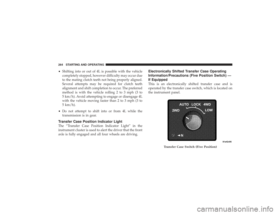
If EquippedThis is an electronically shifted transfer case and is
operated by the transfer case switch, which is located on
the instrument panel.
Transfer Case Switch (Five Position)
264 STARTING AND OPERATING
Page 274 of 532

Electronically Shifted Transfer Case Operating
Information/Precautions (Four Position Switch) —
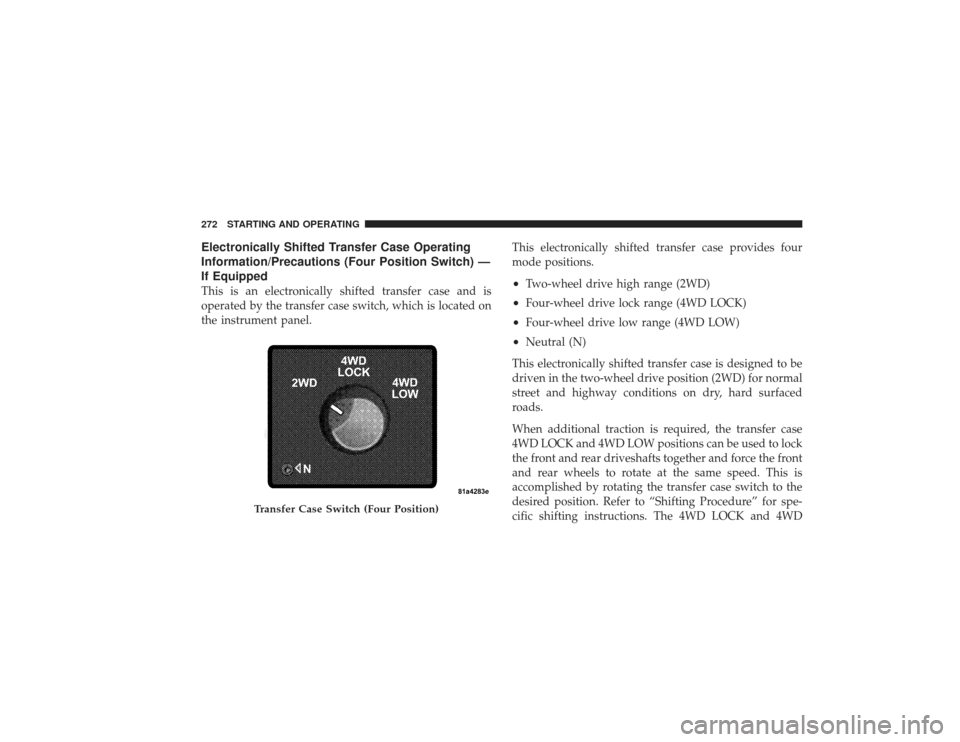
If EquippedThis is an electronically shifted transfer case and is
operated by the transfer case switch, which is located on
the instrument panel.This electronically shifted transfer case provides four
mode positions.
•
Two-wheel drive high range (2WD)
•
Four-wheel drive lock range (4WD LOCK)
•
Four-wheel drive low range (4WD LOW)
•
Neutral (N)
This electronically shifted transfer case is designed to be
driven in the two-wheel drive position (2WD) for normal
street and highway conditions on dry, hard surfaced
roads.
When additional traction is required, the transfer case
4WD LOCK and 4WD LOW positions can be used to lock
the front and rear driveshafts together and force the front
and rear wheels to rotate at the same speed. This is
accomplished by rotating the transfer case switch to the
desired position. Refer to “Shifting Procedure” for spe-
cific shifting instructions. The 4WD LOCK and 4WD
Transfer Case Switch (Four Position)
272 STARTING AND OPERATING
Page 284 of 532
STABILIZER/SWAY BAR SYSTEM — POWER
WAGON ONLYYour vehicle is equipped with an electronic disconnecting
stabilizer/sway bar. This system allows greater front
suspension travel in off-road situations.
Due to the use of taller springs, this vehicle has an
increased ride height of approximately 1.9 in (48.3 mm)
in the front and 1.5 in (38.1 mm) in the rear. A major
advantage to increasing ride height is the positive effect
it has on approach/departure and break over angles.
This system is controlled by the electronic control sway
bar switch located on the instrument panel.The switch has two positions; On-Road and Off-Road.
The system is normally in the On-Road mode, indicated
by a solid green light. The stabilizer/sway bar should
remain in the On-Road mode during normal driving
conditions.
1 — On Road
2 — Off Road
282 STARTING AND OPERATING
Page 331 of 532
WARNING!
Fluid level should be checked on a level surface and
with the engine off to prevent injury from moving
parts and to ensure accurate fluid level reading. Do
not overfill. Use only manufacturer’s recommended
power steering fluid.
If necessary, add fluid to restore to the proper indicated
level. With a clean cloth, wipe any spilled fluid from all
surfaces. Refer to “Fluids, Lubricants, and Genuine
Parts” in Section 7 for the correct fluid type.PARKING BRAKEThe foot-operated parking brake is positioned below the
lower left corner of the instrument panel. To release the
parking brake, pull the parking brake release handle. NOTE:
The “Brake Warning Light” will come on and
flash to indicate that the parking brake is applied. You
must be sure that the parking brake is fully applied
before leaving the vehicle.
Be sure the parking brake is firmly set when parked and
the shift lever is in the PARK position. When parking on
Parking Brake
STARTING AND OPERATING 329
5
Page 374 of 532

the max load inflation pressure (cold) values to switch
the TPMS system to the max load inflation pressure
(cold) low pressure warning threshold. If after pressing
the tire light load inflation switch, and tire pressures are
below the max load inflation pressure (cold) low pressure
warning thresholds, the TPMS low pressure warning
telltale light (located in the instrument cluster) will turn
ON and a chime will sound. The tire pressures are now
required to be inflated to the max load inflation pressure
(cold) values described on the Tire and Loading Informa-
tion label. The Tire and Loading Information label is
located on the drivers side B-pillar. If the tire light load
inflation switch LED turns OFF, the TPMS has been reset
and the TPMS is using the max load inflation pressure
(cold) low pressure warning thresholds.Tire Pressure Monitor System ComponentsThe Tire Pressure Monitor System (TPMS) uses wireless
technology with wheel rim mounted electronic sensors tomonitor tire pressure levels. Sensors, mounted to each
wheel as part of the valve stem, transmit tire pressure
readings to the Receiver Module.
NOTE:
It is particularly important, for you to check the
tire pressure in all of your tires regularly and to maintain
the proper pressure.
The Tire Pressure Monitoring System (TPMS) consists of
the following components:
•
Receiver Module
•
Four Wheel Sensors
•
Two Trigger Modules (mounted in the front wheel-
wells)
•
Tire Light Load Inflation Switch (located in the instru-
ment panel)
•
Tire Pressure Monitoring Telltale Light
372 STARTING AND OPERATING