2009 DODGE RAM 3500 DIESEL wheel
[x] Cancel search: wheelPage 363 of 532

TIRE CHAINSUse “Class U” chains on 2500/3500 model trucks, or
other traction aids that meet SAE Type “U” specifica-
tions.
NOTE:Chains must be the proper size for the vehicle,
as recommended by the chain manufacturer.
CAUTION!
To avoid damage to your vehicle, tires or chains,
observe the following precautions:•
Because of limited chain clearance between tires
and other suspension components, it is important
that only chains in good condition are used. Bro-
ken chains can cause serious vehicle damage. Stop
the vehicle immediately if noise occurs that could
suggest chain breakage. Remove the damaged
parts of the chain before further use.
(Continued)
CAUTION! (Continued)
•
Install chains as tightly as possible and then
retighten after driving about 0.5 mile (0.8 km).
•
Do not exceed 45 mph (72 km/h).
•
Drive cautiously and avoid severe turns and large
bumps, especially with a loaded vehicle.
•
Do not install tire chains on front wheels of 4x2
vehicles.
•
Do not drive for a prolonged period on dry pave-
ment.
•
Observe the tire chain manufacturer’s instructions
on method of installation, operating speed, and
conditions for usage. Always use the lower sug-
gested operating speed of the chain manufacturer
if different than the speed recommended by the
manufacturer.
STARTING AND OPERATING 361
5
Page 364 of 532

These cautions apply to all chain traction devices, includ-
ing link and cable (radial) chains.
Tire chain use is permitted only on the rear tires of 4X2
model trucks.
NOTE:•
The use of class “U” chains is permitted on the front
and rear of 4X4, 2500 model trucks with LT245/
70R17E tires.
•
The use of class “U” chains is permitted on the front
and rear of 4X4, 3500 model trucks with Dual Rear
Wheels and LT235/80R17E tires.
•
On 4X2 2500/3500 model trucks, class “U” snow
chains are permitted on the rear wheels only of
vehicles equipped with LT245/70R17, LT265/70R17,
and LT235/80R17 size tires.
•
On 4x4 2500/3500 SRW (Single Rear Wheel) model
trucks, class “U” snow chains are permitted on the rear
wheels only of vehicles equipped with LT265/70R17E.
CAUTION!
Do not use tire chains on 4x4 model trucks equipped
with P265/70R17, LT275/70R17, P275/60R20, tires.
There may not be adequate clearance for the chains
and you are risking structural or body damage to
your vehicle. Do not use tire chains on the 4X2 front
wheels of 2500/3500 SRW (Single Rear Wheels)
equipped with LT245/70R17, LT265/70R17 LT235/
80R17 tires, or 4X4 front wheels equipped with
LT265/70R17E. There may not be adequate clearance
for the chains and you are risking structural or body
damage to your vehicle.
362 STARTING AND OPERATING
Page 367 of 532

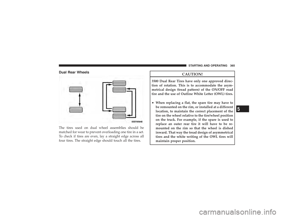
Dual Rear WheelsThe tires used on dual wheel assemblies should be
matched for wear to prevent overloading one tire in a set.
To check if tires are even, lay a straight edge across all
four tires. The straight edge should touch all the tires.
CAUTION!
3500 Dual Rear Tires have only one approved direc-
tion of rotation. This is to accommodate the asym-
metrical design (tread pattern) of the ON/OFF road
tire and the use of Outline White Letter (OWL) tires.•
When replacing a flat, the spare tire may have to
be remounted on the rim, or installed at a different
location, to maintain the correct placement of the
tire on the wheel relative to the tire/wheel position
on the truck. For example, if the spare is used to
replace an outer rear tire it will have to be re-
mounted on the rim so that the wheel is dished
inward. That way the tread design of asymmetrical
tires and the white writing of the OWL tires will
maintain proper position.
STARTING AND OPERATING 365
5
Page 370 of 532

CAUTION!
•
The TPMS has been optimized for the original
equipment tires and wheels. TPMS pressures have
been established for the tire size equipped on your
vehicle. Undesirable system operation or sensor
damage may result when using replacement
equipment that is not of the same size, type, and/or
style. After-market wheels can cause sensor dam-
age. Do not use aftermarket tire sealants or balance
beads if your vehicle is equipped with a TPMS, as
damage to the sensors may result.
•
After inspecting or adjusting the tire pressure
always reinstall the valve stem cap. This will
prevent moisture and dirt from entering the valve
stem, which could damage the Tire Pressure Moni-
toring Sensor.NOTE:
•
The TPMS is not intended to replace normal tire care
and maintenance, nor to provide warning of a tire
failure or condition.
•
The TPMS should not be used as a tire pressure gauge
while adjusting your tire pressure.
•
Driving on a significantly under-inflated tire causes
the tire to overheat and can lead to tire failure.
Under-inflation also reduces fuel efficiency and tire
tread life, and may affect the vehicle’s handling and
stopping ability.
•
The TPMS is not a substitute for proper tire mainte-
nance, and it is the driver ’s responsibility to maintain
correct tire pressure, even if under-inflation has not
reached the level to trigger illumination of the “Tire
Pressure Monitoring Telltale Light.”
•
Seasonal temperature changes will affect tire pressure,
and the TPM system will monitor the actual tire
pressure in the tire.
368 STARTING AND OPERATING
Page 374 of 532

the max load inflation pressure (cold) values to switch
the TPMS system to the max load inflation pressure
(cold) low pressure warning threshold. If after pressing
the tire light load inflation switch, and tire pressures are
below the max load inflation pressure (cold) low pressure
warning thresholds, the TPMS low pressure warning
telltale light (located in the instrument cluster) will turn
ON and a chime will sound. The tire pressures are now
required to be inflated to the max load inflation pressure
(cold) values described on the Tire and Loading Informa-
tion label. The Tire and Loading Information label is
located on the drivers side B-pillar. If the tire light load
inflation switch LED turns OFF, the TPMS has been reset
and the TPMS is using the max load inflation pressure
(cold) low pressure warning thresholds.Tire Pressure Monitor System ComponentsThe Tire Pressure Monitor System (TPMS) uses wireless
technology with wheel rim mounted electronic sensors tomonitor tire pressure levels. Sensors, mounted to each
wheel as part of the valve stem, transmit tire pressure
readings to the Receiver Module.
NOTE:
It is particularly important, for you to check the
tire pressure in all of your tires regularly and to maintain
the proper pressure.
The Tire Pressure Monitoring System (TPMS) consists of
the following components:
•
Receiver Module
•
Four Wheel Sensors
•
Two Trigger Modules (mounted in the front wheel-
wells)
•
Tire Light Load Inflation Switch (located in the instru-
ment panel)
•
Tire Pressure Monitoring Telltale Light
372 STARTING AND OPERATING
Page 375 of 532

Tire Pressure Monitoring Low Pressure Warnings
The “Tire Pressure Monitoring Telltale Light” will
illuminate in the instrument cluster, and an au-
dible chime will be activated when one or more of
the four active road tire pressures are low. Should this
occur, you should stop as soon as possible, check the
inflation pressure of each tire on your vehicle and inflate
each tire to the vehicle’s recommended cold placard
pressure value. The system will automatically update
and the “Tire Pressure Monitoring Telltale Light” will
extinguish once the updated tire pressures have been
received. The vehicle may need to be driven for up to
20 minutes above 15 mph (25 km/h) to receive this
information.
Check TPMS WarningsThe “Tire Pressure Monitoring Telltale Light” (located in
the instrument cluster) will flash on and off for 75 sec-
onds and will remain on solid when a system fault is
detected. The system fault will also sound a chime. If the ignition key is cycled, this sequence will repeat, provid-
ing the system fault still exists. A system fault can occur
by any of the following scenarios:
1. Signal interference due to electronic devices or driving
next to facilities emitting the same Radio Frequencies as
the TPM sensors.
2. Installing aftermarket window tinting that affects ra-
dio wave signals.
3. Accumulation of snow or ice around the wheels or
wheel housings.
4. Using tire chains on the vehicle.
5. Using wheels/tires not equipped with TPM sensors.
6. Loss of communication with the trigger modules or
tire pressure monitoring sensors.
NOTE: Your vehicle is equipped with a non-matching
full size spare wheel and tire assembly.
STARTING AND OPERATING 373
5
Page 384 of 532

Gross Axle Weight Rating (GAWR)The GAWR is the maximum permissible load on the front
and rear axles. The load must be distributed in the cargo
area so that the GAWR of each axle is not exceeded.
Each axle GAWR is determined by the components in the
system with the lowest load carrying capacity (axle,
springs, tires or wheels). Heavier axles or suspension
components sometimes specified by purchasers for in-
creased durability does not necessarily increase the vehi-
cle’s GVWR.Tire SizeThe tire size on the Label represents the actual tire size on
your vehicle. Replacement tires must be equal to the load
capacity of this tire size.Rim SizeThis is the rim size that is appropriate for the tire size
listed.
Inflation PressureThis is the cold tire inflation pressure for your vehicle for
all loading conditions up to full GAWR.Curb WeightThe curb weight of a vehicle is defined as the total weight
of the vehicle with all fluids, including vehicle fuel, at full
capacity conditions, and with no occupants or cargo
loaded into the vehicle. The front and rear curb weight
values are determined by weighing your vehicle on a
commercial scale before any occupants or cargo are
added.LoadingThe actual total weight and the weight of the front and
rear of your vehicle at the ground can best be determined
by weighing it when it is loaded and ready for operation.
The entire vehicle should first be weighed on a commer-
cial scale to insure that the GVWR has not been exceeded.
The weight on the front and rear of the vehicle should
382 STARTING AND OPERATING
Page 390 of 532

Fifth-Wheel HitchA special high platform with a coupling that mounts over
the rear axle of the tow vehicle in the truck bed. Connects
a vehicle and fifth-wheel trailer with a coupling king pin.Gooseneck HitchThe gooseneck hitch employs a pivoted coupling arm
which attaches to a ball mounted in the bed of a pickup
truck. The coupling arm connects to the hitch mounted
over the rear axle in the truck bed.Trailer Hitch ClassificationThe rear bumper is intended to tow trailers up to
2,000 lbs (907 kg) without added equipment or alter-
ations to the standard equipment. Your vehicle may be
factory equipped for safe towing of trailers weighing
over 2,000 lbs (907 kg) with the optional Trailer Tow Prep
Package. See your dealer for package content.
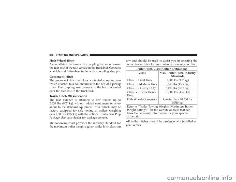
The following chart provides the industry standard for
the maximum trailer weight a given trailer hitch class cantow and should be used to assist you in selecting the
correct trailer hitch for your intended towing condition.
Trailer Hitch Classification Definitions
Class Max. Trailer Hitch Industry Standards
Class I - Light Duty 2,000 lbs (907 kg)
Class II - Medium Duty 3,500 lbs (1587 kg)
Class III - Heavy Duty 5,000 lbs (2268 kg)
Class IV - Extra Heavy
Duty 10,000 lbs (4540 kg)
Fifth Wheel/Gooseneck Greater than 10,000 lbs (4540 kg)
Refer to “Trailer Towing Weights (Maximum Trailer
Weight Ratings)” for the website address that con-
tains the necessary information for your specific
drivetrain.
All trailer hitches should be professionally installed on
your vehicle.
388 STARTING AND OPERATING