Page 201 of 532

CAUTION!
The TPMS has been optimized for the original
equipment tires and wheels. TPMS pressures and
warning have been established for the tire size
equipped on your vehicle. Undesirable system opera-
tion or sensor damage may result when using re-
placement equipment that is not of the same size,
type, and/or style. Aftermarket wheels can cause
sensor damage. Do not use tire sealant from a can, or
balance beads if your vehicle is equipped with a
TPMS, as damage to the sensors may result.
26. Electronic Stability Program (ESP) Indicator Light/
Traction Control System (TCS) Indicator Light — If
Equipped If this indicator light flashes during accelera-
tion, apply as little throttle as possible. While
driving, ease up on the accelerator. Adapt your speed and driving to the prevailing road conditions, and
do not switch off the Electronic Stability Program (ESP),
or Traction Control System (TCS).
27. Transmission Temperature Indicator (Automatic
Transmissions Only)
This light indicates that there is excessive trans-
mission fluid temperature that might occur
with severe usage such as trailer towing. It may
also occur when operating the vehicle in a high
torque converter slip condition, such as 4-wheel-drive
operation (e.g., snow plowing, off- road operation). If this
light comes on, stop the vehicle and run the engine at idle
or faster, with the transmission in NEUTRAL until the
light goes off.
28. Odometer/Trip Odometer Button
Press this button to toggle between the odometer and the
trip odometer display. Holding the button in resets the
trip odometer reading when in trip mode.
UNDERSTANDING YOUR INSTRUMENT PANEL 199
4
Page 202 of 532
29. Fuel Gauge
Shows level of fuel in tank when ignition switch is in the
ON position.
30. Low Fuel LightWhen the fuel level drops to 1/16 tank, the fuel
symbol will light and a single chime will sound.
NOTE: If your vehicle is equipped with an overhead
console module (CMTC), it is possible for DTE to display
“LO FUEL” before the low fuel warning light turns on in
the instrument cluster. This could occur because the low
fuel warning is set to a specified fuel tank volume and
DTE is an estimated distance calculation based on vehicle
fuel economy and remaining fuel tank volume.
Vehicle fuel tank volumes are as follows:•
26 gal (98 L) - 1500 short box models
•
34 gal (128 L) - 1500/2500/3500 short box models
•
35 gal (132 L) - 1500/2500/3500 long box models 31. CRUISE Indicator
This indicator lights when the electronic speed
control system is turned on.
32. Engine Temperature Warning Light This light warns of an overheated engine condi-
tion. As temperatures rise and the gauge ap-
proaches H, this indicator will illuminate and a
single chime will sound after reaching a set threshold.
Further overheating will cause the temperature gauge to
pass H, the indicator will continuously flash and a
continuous chime will occur until the engine is allowed
to cool.
If the light turns on while driving, safely pull over and
stop the vehicle. If the A/C system is on, turn it off. Also,
shift the transmission into NEUTRAL and idle the ve-
hicle. If the temperature reading does not return to
normal, turn the engine off immediately and call for
service. Refer to “If Your Engine Overheats” in Section 6
for more information.
200 UNDERSTANDING YOUR INSTRUMENT PANEL
Page 203 of 532
33. Charging System LightThis light shows the status of the electrical charg-
ing system. The light should come on when the
ignition switch is first turned ON and remain on briefly
as a bulb check. If the light stays on or comes on while
driving, turn off some of the vehicle’s non-essential
electrical devices or increase engine speed (if at idle). If
the charging system light remains on, it means that the
vehicle is experiencing a problem with the charging
system. Obtain SERVICE IMMEDIATELY. See an autho-
rized dealer.
34. Oil Pressure Warning Light This light indicates low engine oil pressure. The
light should turn on momentarily when the engine
is started. If the light turns on while driving, stop the
vehicle and shut off the engine as soon as possible. A
chime will sound for four minutes when this light turns
on. Do not operate the vehicle until the cause is corrected.
This light does not indicate how much oil is in the engine.
The engine oil level must be checked under the hood.
ELECTRONIC DIGITAL CLOCKThe clock and radio each use the display panel built into
the radio. A digital readout shows the frequency and/or
time in hours and minutes (depending on your radio
model) whenever the ignition switch is in the ON or ACC
position.
When the ignition switch is in the OFF position, or when
the radio frequency is being displayed, time keeping is
accurately maintained.
On the RAQ radio the time button alternates the location
of the time and frequency on the display. On the REF only
one of the two, time or frequency, is displayed at a time.
UNDERSTANDING YOUR INSTRUMENT PANEL 201
4
Page 227 of 532
the worldwide standard for time. This makes the sys-
tem’s clock very accurate once the appropriate time zone
and daylight savings information is set.
1. At theMain Menu screen, highlight “Clock Setup”
and press ENTER ORpress and hold the TIME button on
the unit’s faceplate for three seconds. The Clock Setup
screen appears. 2. To show the GPS clock, select “Displayed Clock: GPS
Clock” and press ENTER.
3. To adjust the time zone, Select “Time Zone” and press
ENTER. Select the appropriate time zone and press
ENTER.
4. To turn daylight savings on or off, select “Daylight
Savings” and press ENTER. Select “On” or “Off” and
press ENTER.
5. Select DONE to exit from the clock setting mode. Press
ENTER to save your changes. If you press CANCEL or
NAV then your changes will not be saved.
UNDERSTANDING YOUR INSTRUMENT PANEL 225
4
Page 228 of 532
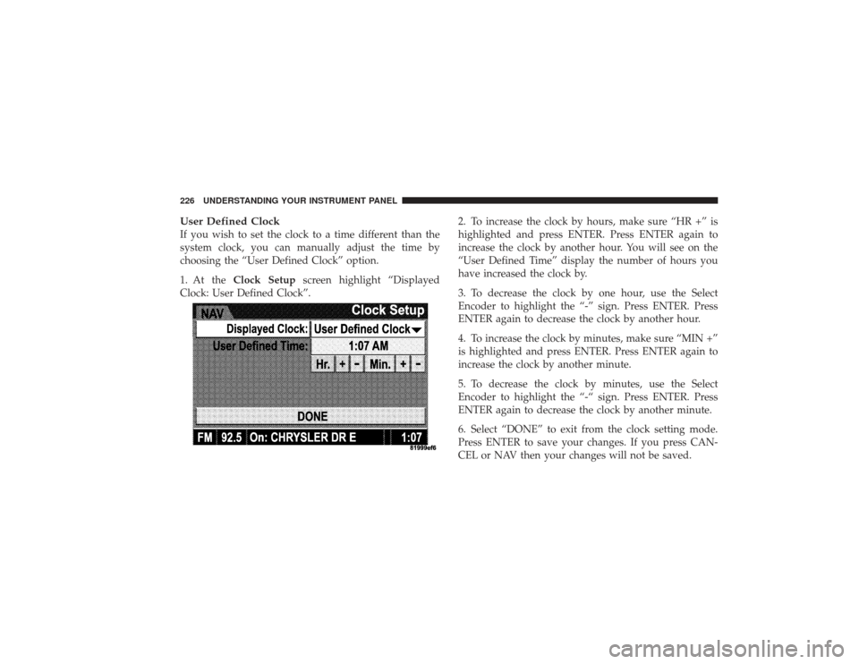
User Defined ClockIf you wish to set the clock to a time different than the
system clock, you can manually adjust the time by
choosing the “User Defined Clock” option.
1. At theClock Setup screen highlight “Displayed
Clock: User Defined Clock”. 2. To increase the clock by hours, make sure “HR +” is
highlighted and press ENTER. Press ENTER again to
increase the clock by another hour. You will see on the
“User Defined Time” display the number of hours you
have increased the clock by.
3. To decrease the clock by one hour, use the Select
Encoder to highlight the “-” sign. Press ENTER. Press
ENTER again to decrease the clock by another hour.
4. To increase the clock by minutes, make sure “MIN +”
is highlighted and press ENTER. Press ENTER again to
increase the clock by another minute.
5. To decrease the clock by minutes, use the Select
Encoder to highlight the “-“ sign. Press ENTER. Press
ENTER again to decrease the clock by another minute.
6. Select “DONE” to exit from the clock setting mode.
Press ENTER to save your changes. If you press CAN-
CEL or NAV then your changes will not be saved.226 UNDERSTANDING YOUR INSTRUMENT PANEL
Page 235 of 532
3. Do not apply paper or tape to the disc; avoid scratch-
ing the disc.
4. Do not use solvents such as benzene, thinner, cleaners,
or anti-static sprays.
5. Store the disc in its case after playing.
6. Do not expose the disc to direct sunlight.
7. Do not store the disc where temperatures may become
too high.
NOTE:If you experience difficulty in playing a particu-
lar disc, it may be damaged (i.e., scratched, reflective
coating removed, a hair, moisture or dew on the disc)
oversized, or have protection encoding. Try a known
good disc before considering disc player service.
RADIO OPERATION AND CELLULAR PHONESUnder certain conditions, the operation of a cellular
phone in your vehicle can cause erratic or noisy perfor-
mance from your radio. This condition may be lessened
or eliminated by relocating the cellular phone antenna.
This condition is not harmful to the radio. If your radio
performance does not satisfactorily “clear” by the repo-
sitioning of the antenna, it is recommended that the radio
volume be turned down or off during cellular phone
operation.
UNDERSTANDING YOUR INSTRUMENT PANEL 233
4
Page 239 of 532
Air Conditioning and Heating — If EquippedAir Conditioning Operation
To turn on the Air Conditioning, set the fan
control at any speed and press the snowflake
button located at the right of the control panel.
Conditioned air will be directed through the
outlets selected by the mode control. A light in the
snowflake button shows that the air conditioning is on.
Press the button a second time to turn the air condition-
ing off.
Slight changes in engine speed or power may be noticed
when the air conditioning compressor is on. This is a
normal occurrence as the compressor will cycle on and
off to maintain comfort and increase fuel economy.
Air Conditioning And Heating
UNDERSTANDING YOUR INSTRUMENT PANEL 237
4
Page 242 of 532
edges of the instrument panel. The demisters also pro-
vide extra air ducts for circulation. They are in operation
whenever the Floor, Mix or Defrost modes are in use. To
remove frost from the side windows, it is best to use the
full defrost mode.
NOTE:When you turn off the engine you may hear a
hissing sound from under the hood for a short period of
time. This is a normal condition that occurs if the air
conditioning system has been on. It is not an indication of
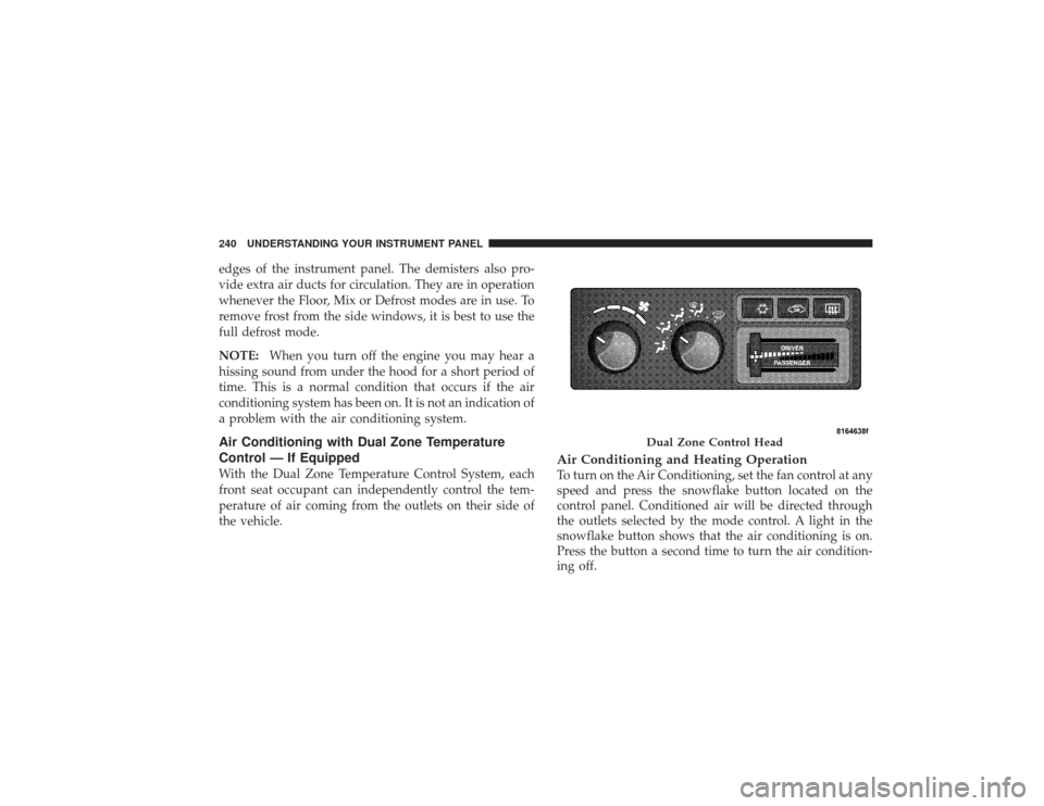
a problem with the air conditioning system.Air Conditioning with Dual Zone Temperature
Control — If EquippedWith the Dual Zone Temperature Control System, each
front seat occupant can independently control the tem-
perature of air coming from the outlets on their side of
the vehicle.
Air Conditioning and Heating OperationTo turn on the Air Conditioning, set the fan control at any
speed and press the snowflake button located on the
control panel. Conditioned air will be directed through
the outlets selected by the mode control. A light in the
snowflake button shows that the air conditioning is on.
Press the button a second time to turn the air condition-
ing off.
Dual Zone Control Head
240 UNDERSTANDING YOUR INSTRUMENT PANEL