Page 144 of 469

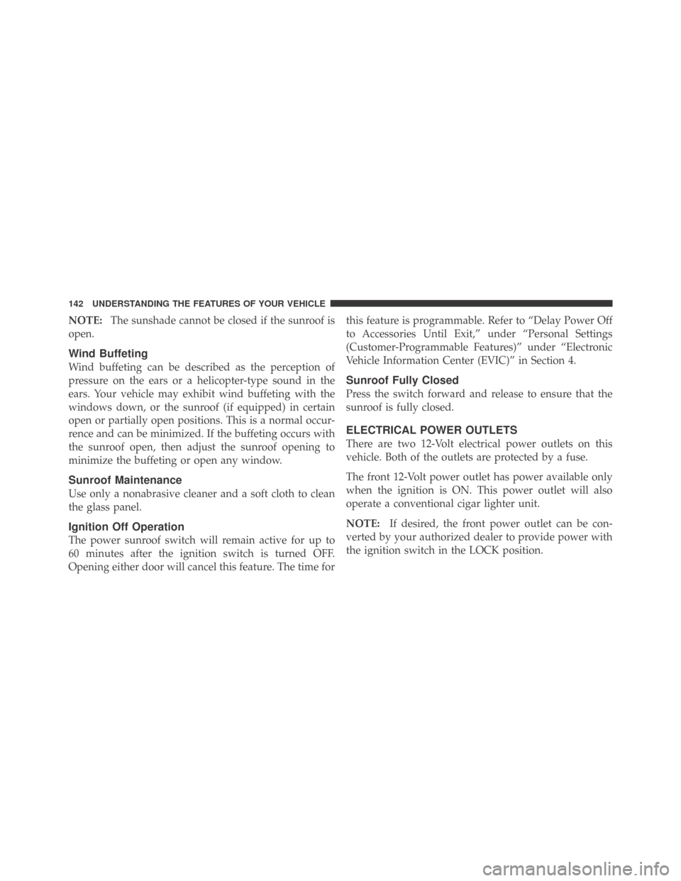
NOTE:The sunshade cannot be closed if the sunroof is
open.
Wind Buffeting
Wind buffeting can be described as the perception of
pressure on the ears or a helicopter-type sound in the
ears. Your vehicle may exhibit wind buffeting with the
windows down, or the sunroof (if equipped) in certain
open or partially open positions. This is a normal occur-
rence and can be minimized. If the buffeting occurs with
the sunroof open, then adjust the sunroof opening to
minimize the buffeting or open any window.
Sunroof Maintenance
Use only a nonabrasive cleaner and a soft cloth to clean
the glass panel.
Ignition Off Operation
The power sunroof switch will remain active for up to
60 minutes after the ignition switch is turned OFF.
Opening either door will cancel this feature. The time forthis feature is programmable. Refer to “Delay Power Off
to Accessories Until Exit,” under “Personal Settings
(Customer-Programmable Features)” under “Electronic
Vehicle Information Center (EVIC)” in Section 4.
Sunroof Fully Closed
Press the switch forward and release to ensure that the
sunroof is fully closed.
ELECTRICAL POWER OUTLETS
There are two 12-Volt electrical power outlets on this
vehicle. Both of the outlets are protected by a fuse.
The front 12-Volt power outlet has power available only
when the ignition is ON. This power outlet will also
operate a conventional cigar lighter unit.
NOTE:If desired, the front power outlet can be con-
verted by your authorized dealer to provide power with
the ignition switch in the LOCK position.
142 UNDERSTANDING THE FEATURES OF YOUR VEHICLE
Page 163 of 469

19. Odometer / Electronic Vehicle Information Center
(EVIC) Display Area
The odometer shows the total distance the vehicle has
been driven. The trip odometer shows individual trip
mileage. Refer to “Trip Odometer Button” for additional
information.
NOTE:U.S. Federal regulations require upon transfer of
vehicle ownership, the seller certify the mileage the
vehicle has been driven. Therefore, if the odometer
reading is changed because of repair or replacement, be
sure to keep a record of the reading before and after the
service so that the correct mileage can be determined.
Vehicle Warning Messages
When the appropriate conditions exist, the following
warning messages will display in the odometer:
ECO......................Fuel Saver Indicator
Check gascap........Loose Fuel Filler Cap MessageLo tirE...................... LowTirePressure
Change Oil................ OilChange Required
noFUSE..........................Fuse Fault
On vehicles equipped with a Premium Instrument Clus-
ter, this display shows the Electronic Vehicle Information
Center (EVIC) messages when the appropriate conditions
exist. Refer to Electronic Vehicle Information Center
(EVIC) in this section for more information.
ECO (Fuel Saver Indicator) — If Equipped
The ECO indicator will illuminate when you are driving
in a fuel efficient manner and can be used to modify
driving habits in order to increase fuel economy. The
ECO display will toggle on and off depending on driving
habits and vehicle usage.
Check gascap
If the vehicle diagnostic system determines that the fuel
filler cap is loose, improperly installed, or damaged, a
“Check gascap” message will display in the odometer
4
UNDERSTANDING YOUR INSTRUMENT PANEL 161
Page 366 of 469

▫Exhaust System..................... 381
▫Cooling System..................... 384
▫Brake System....................... 389
▫Clutch Hydraulic System — Manual
Transmission (If Equipped)............. 392
▫Manual Transmission — If Equipped...... 392
▫Automatic Transmission — If Equipped.... 393
▫Rear Axle.......................... 394
▫Appearance Care And Protection From
Corrosion.......................... 395
�Fuses.............................. 400
▫Integrated Power Module (IPM).......... 400
▫Rear Power Distribution Center.......... 403
�Vehicle Storage....................... 407�Replacement Light Bulbs................ 408
�Bulb Replacement..................... 409
▫Low Beam Headlamp, High Beam
Headlamp, Park/Turn Lamp — Models With
Halogen Headlamps — If Equipped....... 409
▫Low Beam Headlamp, High Beam
Headlamp, And Park/Turn Lamp — Models
With High Intensity Discharge (HID)
Headlamps — If Equipped............. 409
▫Front/Rear Side Marker Lamp........... 409
▫Tail/Turn And Stop Lamp.............. 410
▫Center Tail/Backup Lamp.............. 412
▫Center High-Mounted Stop Lamp
(CHMSL).......................... 413
▫License Lamp....................... 413
364 MAINTAINING YOUR VEHICLE
Page 402 of 469
NOTE:The cupholder cannot be removed.
FUSES
Integrated Power Module (IPM)
The Integrated Power Module (IPM) is located in the
engine compartment. This module contains fuses and
relays.
Integrated Power Module
400 MAINTAINING YOUR VEHICLE
Page 403 of 469
CAUTION!
•When installing the integrated power module
cover, it is important to ensure the cover is prop-
erly positioned and fully latched. Failure to do so
may allow water to get into the integrated power
module and possibly result in an electrical system
failure.
•When replacing a blown fuse, it is important to
use only a fuse having the correct amperage rating.
The use of a fuse with a rating other than indicated
may result in a dangerous electrical system over-
load. If a properly rated fuse continues to blow, it
indicates a problem in the circuit that must be
corrected.
Cavity Car-
tridge
FuseMini-
FuseDescription
1 — 15 Amp
BlueWasher Motor
2 — 25 Amp
NeutralPowertrain Control
Module (PCM)
3 — 25 Amp
NeutralIgnition Run/Start
4 — 25 Amp
NeutralEGR Solenoid/
Alternator
5 ———
6 — 25 Amp
NeutralIgnition Coils/Injectors
7 ———
8 — 30 Amp
GreenStarter
9 ———
7
MAINTAINING YOUR VEHICLE 401
Page 404 of 469
Cavity Car-
tridge
FuseMini-
FuseDescription
10 30 Amp
Pink— Windshield Wiper
11 30 Amp
Pink— Anti-Lock Brake System
(ABS) Valves
12 40 Amp
Green— Radiator Fan Lo/High
13 50 Amp
Red— Anti-Lock Brake System
(ABS) Pump Motor
14———
15 50 Amp
Red— Radiator FanCavity Car-
tridge
FuseMini-
FuseDescription
16———
17———
18———
19———
20———
21———
22———
402 MAINTAINING YOUR VEHICLE
Page 405 of 469
Rear Power Distribution Center
There is also a power distribution center located in the
trunk under the spare tire access panel. This center
contains fuses and relays.
Access Panel
Rear Power Distribution Center
7
MAINTAINING YOUR VEHICLE 403
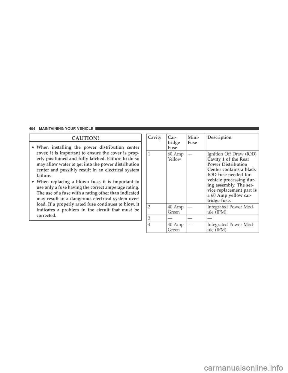
Page 406 of 469

CAUTION!
•When installing the power distribution center
cover, it is important to ensure the cover is prop-
erly positioned and fully latched. Failure to do so
may allow water to get into the power distribution
center and possibly result in an electrical system
failure.
•When replacing a blown fuse, it is important to
use only a fuse having the correct amperage rating.
The use of a fuse with a rating other than indicated
may result in a dangerous electrical system over-
load. If a properly rated fuse continues to blow, it
indicates a problem in the circuit that must be
corrected.
Cavity Car-
tridge
FuseMini-
FuseDescription
1 60 Amp
Yellow— Ignition Off Draw (IOD)
Cavity 1 of the Rear
Power Distribution
Center contains a black
IOD fuse needed for
vehicle processing dur-
ing assembly. The ser-
vice replacement part is
a 60 Amp yellow car-
tridge fuse.
2 40 Amp
Green— Integrated Power Mod-
ule (IPM)
3 ———
4 40 Amp
Green— Integrated Power Mod-
ule (IPM)
404 MAINTAINING YOUR VEHICLE