Page 372 of 469

5. Approximately 15 seconds later, one of two things will
happen:
a. The MIL will flash for about 10 seconds and then
return to being fully illuminated until you turn OFF
the ignition key or start the engine. This means that the
vehicle’s OBD II system isnot readyand you should
notproceed to the I/M station.
b. The MIL will not flash at all and will remain fully
illuminated until you turn OFF the ignition key or start
the engine. This means that the vehicle’s OBD II
system isready,and you can proceed to the I/M
station.
If the OBD II system isnot ready,you should see an
authorized dealer or repair facility. If this vehicle was
recently serviced or had a battery failure or replacement,
you may need to do nothing more than drive the vehicleas you normally would in order for the OBD II system to
update. A recheck with the above test routine may then
indicate that the system is now ready.
Regardless of whether the vehicle’s OBD II system is
ready or not ready, if the MIL is illuminated during
normal vehicle operation, you should have the vehicle
serviced before going to the I/M station. The I/M station
can fail the vehicle because the MIL is on with the engine
running.
REPLACEMENT PARTS
Use of genuine MOPAR�parts for normal/scheduled
maintenance and repairs is highly recommended to en-
sure the designed performance. Damage or failures
caused by the use of non-MOPAR�parts for maintenance
and repairs will not be covered by the manufacturer’s
warranty.
370 MAINTAINING YOUR VEHICLE
Page 385 of 469

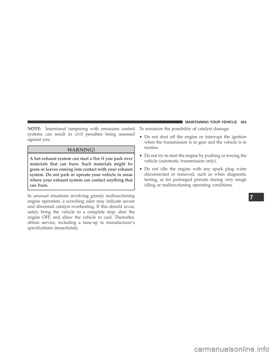
NOTE:Intentional tampering with emissions control
systems can result in civil penalties being assessed
against you.
WARNING!
A hot exhaust system can start a fire if you park over
materials that can burn. Such materials might be
grass or leaves coming into contact with your exhaust
system. Do not park or operate your vehicle in areas
where your exhaust system can contact anything that
can burn.
In unusual situations involving grossly malfunctioning
engine operation, a scorching odor may indicate severe
and abnormal catalyst overheating. If this should occur,
safely bring the vehicle to a complete stop, shut the
engine OFF, and allow the vehicle to cool. Thereafter,
obtain service, including a tune-up to manufacturer’s
specifications immediately.To minimize the possibility of catalyst damage:
•Do not shut off the engine or interrupt the ignition
when the transmission is in gear and the vehicle is in
motion.
•Do not try to start the engine by pushing or towing the
vehicle (automatic transmission only).
•Do not idle the engine with any spark plug wires
disconnected or removed, such as when diagnostic
testing, or for prolonged periods during very rough
idling or malfunctioning operating conditions.
7
MAINTAINING YOUR VEHICLE 383
Page 386 of 469

Cooling System
WARNING!
•When working near the radiator cooling fan, dis-
connect the fan motor lead or turn the ignition
switch to the LOCK position. The fan is tempera-
ture controlled and can start at any time the
ignition switch is in the ON position.
•You or others can be badly burned by hot coolant
or steam from your radiator. If you see or hear
steam coming from under the hood, do not open
the hood until the radiator has had time to cool.
Never try to open a cooling system pressure cap
when the radiator is hot.
Coolant Checks
Check engine coolant (antifreeze) protection every
12 months (before the onset of freezing weather, where
applicable). If coolant is dirty or rusty in appearance, thesystem should be drained, flushed, and refilled with
fresh coolant. Check the front of the radiator for any
accumulation of bugs, leaves, etc. If dirty, clean by gently
spraying water from a garden hose vertically down the
face of the condenser.
Check the coolant recovery bottle tubing for brittle rub-
ber, cracking, tears, cuts, and tightness of the connection
at the bottle and radiator. Inspect the entire system for
leaks.
With the engine at normal operating temperature (but
not running), check the cooling system pressure cap for
proper vacuum sealing by draining a small amount of
coolant from the radiator drain cock. If the cap is sealing
properly, the engine coolant (antifreeze) will begin to
drain from the coolant recovery bottle. DO NOT RE-
MOVE THE COOLANT PRESSURE CAP WHEN THE
COOLING SYSTEM IS HOT.
384 MAINTAINING YOUR VEHICLE
Page 403 of 469
CAUTION!
•When installing the integrated power module
cover, it is important to ensure the cover is prop-
erly positioned and fully latched. Failure to do so
may allow water to get into the integrated power
module and possibly result in an electrical system
failure.
•When replacing a blown fuse, it is important to
use only a fuse having the correct amperage rating.
The use of a fuse with a rating other than indicated
may result in a dangerous electrical system over-
load. If a properly rated fuse continues to blow, it
indicates a problem in the circuit that must be
corrected.
Cavity Car-
tridge
FuseMini-
FuseDescription
1 — 15 Amp
BlueWasher Motor
2 — 25 Amp
NeutralPowertrain Control
Module (PCM)
3 — 25 Amp
NeutralIgnition Run/Start
4 — 25 Amp
NeutralEGR Solenoid/
Alternator
5 ———
6 — 25 Amp
NeutralIgnition Coils/Injectors
7 ———
8 — 30 Amp
GreenStarter
9 ———
7
MAINTAINING YOUR VEHICLE 401
Page 406 of 469

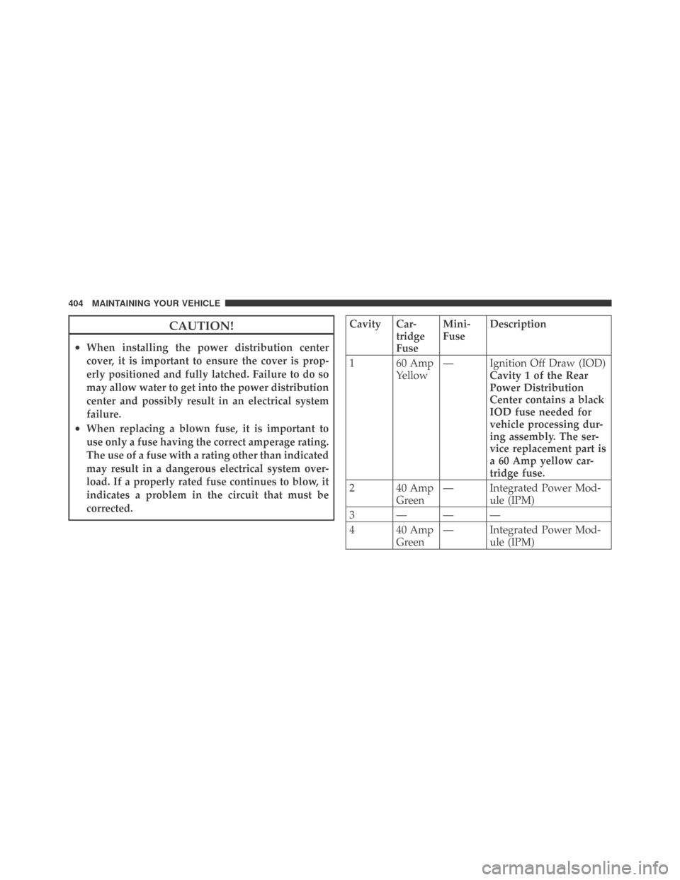
CAUTION!
•When installing the power distribution center
cover, it is important to ensure the cover is prop-
erly positioned and fully latched. Failure to do so
may allow water to get into the power distribution
center and possibly result in an electrical system
failure.
•When replacing a blown fuse, it is important to
use only a fuse having the correct amperage rating.
The use of a fuse with a rating other than indicated
may result in a dangerous electrical system over-
load. If a properly rated fuse continues to blow, it
indicates a problem in the circuit that must be
corrected.
Cavity Car-
tridge
FuseMini-
FuseDescription
1 60 Amp
Yellow— Ignition Off Draw (IOD)
Cavity 1 of the Rear
Power Distribution
Center contains a black
IOD fuse needed for
vehicle processing dur-
ing assembly. The ser-
vice replacement part is
a 60 Amp yellow car-
tridge fuse.
2 40 Amp
Green— Integrated Power Mod-
ule (IPM)
3 ———
4 40 Amp
Green— Integrated Power Mod-
ule (IPM)
404 MAINTAINING YOUR VEHICLE
Page 407 of 469
Cavity Car-
tridge
FuseMini-
FuseDescription
5 30 Amp
Pink— Heated Seats - if
equipped
6 — 20 Amp
YellowFuel Pump
7 — 15 Amp
BlueSub Amp - if equipped
8 — 15 Amp
BlueDiagnostic Link Connec-
tor (DLC)/Wireless Con-
trol Module (WCM)/
Wireless Ignition Node
(WIN)
9 — 20 Amp
YellowPower Outlet
10———
11*———
12*———Cavity Car-
tridge
FuseMini-
FuseDescription
13*———
14 — 10 Amp
RedAC Heater Control/
Cluster/Security Mod-
ule - if equipped
15———
16———
17 — 20 Amp
YellowCluster
18 — 20 Amp
YellowSelectable Power Outlet
19 — 10 Amp
RedStop Lights
20———
21———
22———
7
MAINTAINING YOUR VEHICLE 405
Page 408 of 469
Cavity Car-
tridge
FuseMini-
FuseDescription
23———
24———
25———
26———
27 — 10 Amp
RedOccupant Restraint Con-
troller (ORC)
28 — 10 Amp
RedIgnition Run
29 — 5 Amp
OrangeCluster/Electronic Sta-
bility Program (ESP)/
Powertrain Control
Module (PCM)/STOP
LIGHT Switch
30 — 10 Amp
RedDoor Modules/Power
Mirrors/Steering Con-
trol Module (SCM)Cavity Car-
tridge
FuseMini-
FuseDescription
31———
32———
33———
34———
35 — 5 Amp
OrangeAntenna Module - if
equipped/Power Mir-
rors
36 — 25 Amp
ClearHands-Free Phone - if
equipped/Radio/
Amplifier Feed
37 — 15 Amp
BlueTransmission
38 — 10 Amp
RedCargo Light/Vehicle In-
formation Module - if
equipped
406 MAINTAINING YOUR VEHICLE
Page 454 of 469

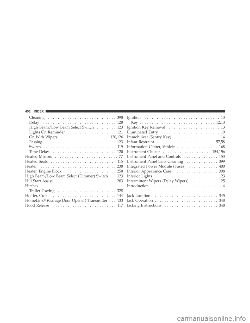
Cleaning............................ 398
Delay .............................. 120
High Beam/Low Beam Select Switch........ 123
Lights On Reminder.................... 121
On With Wipers....................120,126
Passing............................. 123
Switch .............................. 119
TimeDelay .......................... 120
Heated Mirrors.......................... 77
Heated Seats........................... 115
Heater............................... 230
Heater, Engine Block..................... 250
High Beam/Low Beam Select (Dimmer) Switch . . 123
Hill Start Assist......................... 283
Hitches
TrailerTowing ........................ 328
Holder,Cup ........................... 144
HomeLink�(Garage Door Opener) Transmitter . . . 133
Hood Release.......................... 117Ignition............................... 13
Key ............................... 12,13
Ignition Key Removal..................... 13
Illuminated Entry........................ 19
Immobilizer (Sentry Key)................... 14
Infant Restraint........................ 57,58
Information Center, Vehicle................. 168
Instrument Cluster....................154,156
Instrument Panel and Controls.............. 153
Instrument Panel Lens Cleaning............. 399
Integrated Power Module (Fuses)............ 400
Interior Appearance Care.................. 398
InteriorLights .......................... 123
Intermittent Wipers (Delay Wipers)........... 125
Introduction............................. 4
Jack Location........................... 345
Jack Operation.......................... 348
Jacking Instructions...................... 348
452 INDEX