Page 298 of 543
Press and hold the INFO button again for three seconds
to return to�elapsed time� display.
Operation Instructions - Auxiliary Mode
The auxiliary (AUX) jack is an audio input jack which
allows the user to plug in a portable device such as an
MP3 player or cassette player and utilize the vehicle’s
audio system to amplify the source and play through the
vehicle speakers.
Pressing the AUX button will change the mode to auxil-
iary device if the AUX jack is connected.
NOTE:The AUX device must be turned on and the
device’s volume set to the proper level. If the AUX audio
is not loud enough, turn the device’s volume up. If the
AUX audio sounds distorted, turn the device’s volume
down.
TIME Button (Auxiliary Mode)
Press this button to change the display to time of day. The
time of day will display for five seconds (when the
ignition is OFF).
Operating Instructions - uconnect™ phone (If
Equipped)
Refer to “uconnect™ phone” in Section 3.
Operating Instructions - uconnect™ studios
(Satellite Radio) (If Equipped)
Refer to “uconnect™ studios (Satellite Radio)” in this
section.
UNIVERSAL CONSUMER INTERFACE (UCI) — IF
EQUIPPED
NOTE: This section is for sales code RES and REQ/
REL/RET radios only with uconnect™. For sales code
RER, REN, REP, REW or REZ touch-screen radio UCI
296 UNDERSTANDING YOUR INSTRUMENT PANEL
Page 301 of 543

•Jump backward in the current track by pressing and
holding the <
button long enough will take you to the beginning
of the current track.
•Jump forward in the current track by pressing and
holding the FF>> button.
•A single press backward << RWor forward FF>> will
jump backward or forward respectively, for five
seconds.
•Use the << SEEKandSEEK >> buttons to jump to the
previous or next track. If the << SEEKbutton is
pressed during the first two seconds of the track, it will
jump to the previous track in the list; if you press this
button at any other time in the track, it will jump to the
beginning of the track. If you press the SEEK>>
button during play mode, it will jump to the next track
in the list.
•While a track is playing, press the INFObutton to see
the associated metadata (artist, track title, album, etc.)
for that track. Pressing the INFObutton again jumps
to the next screen of data for that track. Once you have
seen all screens, the last INFObutton press will take
you back to the play mode screen on the radio.
•Pressing the REPEATbutton will change the iPod�
mode to repeat the current playing track.
•Press the SCANbutton to use iPod� scan mode, which
will play the first five seconds of each track in the
current list and then forward to the next song. To stop
SCAN mode and start playing the desired track, when
it is playing the track, press the SCANbutton again.
During Scan mode, you can also press the << SEEK
and SEEK >> buttons to select the previous and next
tracks.
•RND button (available on sales code RES radio only):
Pressing this button toggles between Shuffle ON and
4
UNDERSTANDING YOUR INSTRUMENT PANEL 299
Page 308 of 543
•Display Sirius ID number — Press the AUDIO/
SELECT button to display the Sirius ID number. This
number is used to activate, deactivate, or change the
Sirius subscription.
SET Button – To Set the Pushbutton Memory
When you are receiving a channel that you wish to
commit to pushbutton memory, press the SET button.
The symbol SET 1 will now show in the display window.
Select the button (1-6) you wish to lock onto this channel
and press and release that button. If a button is not
selected within five seconds after pressing the SET but-
ton, the channel will continue to play but will not be
stored into pushbutton memory.
You may add a second channel to each pushbutton by
repeating the above procedure with this exception: Press
the SET button twice and SET 2 will show in the display
window. Each button can be set for SET 1 and SET 2. This
allows a total of 12 Satellite channels to be stored intopushbutton memory. The channels stored in SET 2
memory can be selected by pressing the pushbutton
twice.
Every time a preset button is used, a corresponding
button number will display.Buttons1-6
These buttons tune the radio to the channels that you
commit to pushbutton memory (12 Satellite stations).
Operating Instructions — uconnect
�phone (If
Equipped)
Refer to “uconnect� phone” in Section 3.
Operating Instructions — Video Entertainment
System (VES)™ (If Equipped)
Refer to separate “Video Entertainment System (VES)™
Guide.”
306 UNDERSTANDING YOUR INSTRUMENT PANEL
Page 396 of 543
WARNING!
•Never have any smoking materials lit in or near
the vehicle when the gas cap is removed or the
tank filled.
•Never add fuel when the engine is running. This is
in violation of most state and federal fire regula-
tions and will cause the “Malfunction Indicator
Light” to turn on.
NOTE:
•Tighten the fuel filler cap until you hear a “clicking”
sound. This is an indication that the fuel filler cap is
properly tightened.
•If the gas cap is not tightened properly, the “Malfunc-
tion Indicator Light” may come on. Be sure the gas cap
is tightened every time the vehicle is refueled.
WARNING!
A fire may result if gasoline is pumped into a
portable container that is inside of a vehicle. You
could be burned. Always place gas containers on the
ground while filling.
Loose Fuel Filler Cap Message
If the gASCAP message is displayed in the instrument
cluster, this signifies a leak or change in the evaporative
system is detected. Sometimes this is the result of a
loosely fitting (or possibly damaged) filler cap. Tighten
the fuel filler cap properly and press the odometer reset
button to turn the gASCAPmessage off.
Make sure that the fuel filler cap is tightened each time
the vehicle is refueled.
394 STARTING AND OPERATING
Page 430 of 543
of operation, and after each time a tire is changed, to
allow the wheel nuts to become properly set. All nuts
should first be firmly seated against the wheel. The nuts
should then be tightened to recommended torque.
Tighten the nuts to final torque in increments. Progress
around the bolt circle, tightening the nut opposite to the
nut just previously tightened until final torque is
achieved. Recommended torque is 95 ft lbs (130 N·m).
Secure The Spare Tire As Follows:
1. Assemble the winch handle extensions to form a “T”
and fit the winch “T” handle over the drive nut. Rotate
the nut to the left until the winch mechanism stops
turning freely. This will allow enough slack in the cable to
allow you to pull the wheel spacer out from under the
vehicle.
WARNING!
A loose compact spare tire/cover assembly, thrown
forward in a collision or hard stop could endanger
the occupants of the vehicle. Always stow the com-
pact spare tire with the cover assembly in the place
provided.
CAUTION!
The winch mechanism is designed for use with the
winch “T” handle only. Use of an air wrench or other
power tools is not recommended and can damage the
winch.
2. Assemble the winch handle extensions to form the
spare tire hook, and pull the wheel spacer from under the
vehicle.
428 WHAT TO DO IN EMERGENCIES
Page 448 of 543
Change Engine Oil
The oil change indicator system will remind you that it is
time to take your vehicle in for scheduled maintenance.
Refer to the “Maintenance Schedule” in Section 8 of this
manual for information on this system.
NOTE: Under no circumstances should oil change
intervals exceed 6,000 miles (10 000 km) or six months,
whichever occurs first.
Engine Oil Selection
For best performance and maximum protection under all
types of operating conditions, the manufacturer only
recommends engine oils that are API certified and meet
the requirements of Chrysler Material Standard MS-6395.
American Petroleum Institute (API) Engine Oil
Identification Symbol
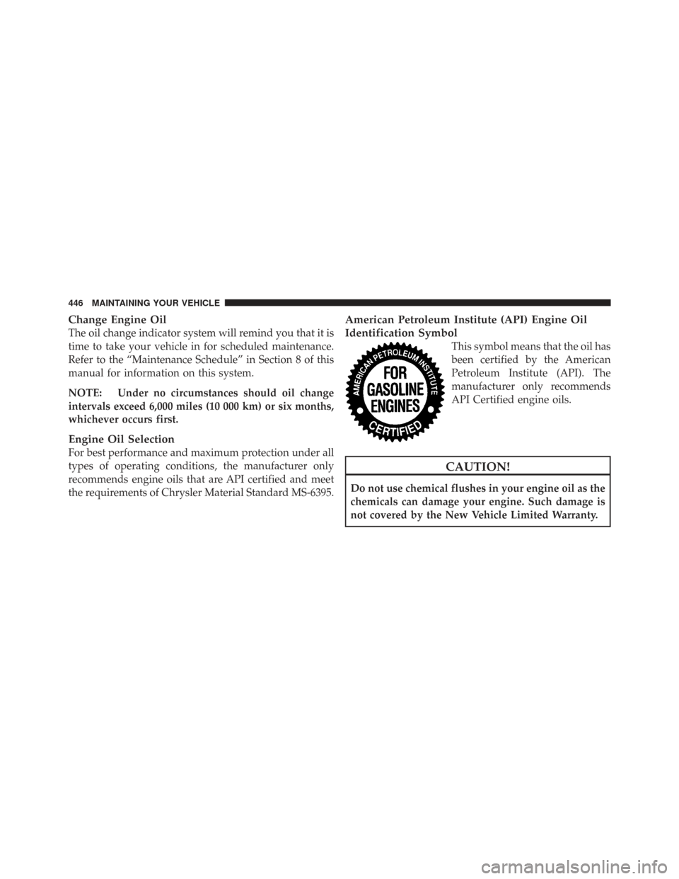
This symbol means that the oil has
been certified by the American
Petroleum Institute (API). The
manufacturer only recommends
API Certified engine oils.
CAUTION!
Do not use chemical flushes in your engine oil as the
chemicals can damage your engine. Such damage is
not covered by the New Vehicle Limited Warranty.
446 MAINTAINING YOUR VEHICLE
Page 451 of 543
used to assure most efficient service. MOPAR�engine air
cleaner filters are a high quality filter and are
recommended.
Exhaust System
The best protection against carbon monoxide entry into
the vehicle body is a properly maintained engine exhaust
system.
Whenever a change is noticed in the sound of the exhaust
system, when exhaust fumes can be detected inside the
vehicle, or when the underside or rear of the vehicle is
damaged, have a competent mechanic inspect the com-
plete exhaust system and adjacent body areas for broken,
damaged, deteriorated, or mispositioned parts. Open
seams or loose connections could permit exhaust fumes
to seep into the passenger compartment. In addition,
inspect the exhaust system each time the vehicle is raised
for lubrication or oil change. Replace as required.
WARNING!
Exhaust gases can injure or kill. They contain carbon
monoxide (CO) which is colorless and odorless.
Breathing it can make you unconscious and can
eventually poison you. To avoid breathing CO, refer
to “Exhaust Gas” in the Safety Tips section of this
manual.
CAUTION!
The catalytic converter requires the use of unleaded
fuel only. Leaded gasoline will destroy the effective-
ness of the catalyst as an emissions control device
and may seriously reduce engine performance and
cause serious damage to the engine.
7
MAINTAINING YOUR VEHICLE 449
Page 494 of 543
EMISSIONS CONTROL SYSTEM MAINTENANCE
The Scheduled Maintenance services listed inbold type
must be done at the times or mileages specified to ensure
the continued proper functioning of the emissions control
system. These and all other maintenance services in-
cluded in this manual, should be done to provide best
vehicle performance and reliability. More frequent main-
tenance may be needed for vehicles in severe operating
conditions, such as dusty areas and very short trip
driving.
Inspection and service should also be done anytime a
malfunction is suspected.
NOTE: Maintenance, replacement or repair of the emis-
sions control devices and systems on your vehicle may be
performed by any automotive repair establishment or
individual using any automotive part that has been
certified pursuant to U.S. EPA or in the State of Califor-
nia, California Air Resources Board regulations.
MAINTENANCE SCHEDULE
The oil change indicator system will remind you that it is
time to take your vehicle in for scheduled maintenance.
On Non-EVIC equipped vehicles, CHAngE OILwill
flash in the instrument cluster odometer and a single
chime will sound, indicating that an oil change is neces-
sary.
On Electronic Vehicle Information Center (EVIC)
equipped vehicles, Oil Change Required will be dis-
played in the EVIC and a single chime will sound,
indicating that an oil change is necessary.
Based on engine operation conditions, the oil change
indicator message will illuminate. This means that ser-
vice is required for your vehicle. Have your vehicle
serviced as soon as possible, within the next 500 miles
(805 km).
8
M A I
N T
E
N A
N CE
S
C
H E
D
U L
E
S492 MAINTENANCE SCHEDULES