Page 344 of 410
CavityCartridge
Fuse Mini-Fuse Description
15 50 Amp Red RAD Fan
Relay
Battery Feed
16 15 Amp Lt.
BlueIGN Run/
Acc Cigar
Ltr/Sunroof
17 10 Amp Red IOD Feed
CVT Mod/
Mod_Wcm
18 40 Amp
Green ASD Relay
Contact
Feed
19 20 Amp
YellowPWR Amp
1 & Amp 2
Feed
20 15 Amp Lt.
BlueIOD Feed
RadioCavity
Cartridge
Fuse Mini-Fuse Description
21 10 Amp Red IOD Feed
Intrus
Mod/Siren
22 10 Amp Red IGN RUN
Hvac/
Compass
Sensor
23 15 Amp Lt.
BlueENG ASD
Relay Feed
3
24 25 Amp
NaturalPWR
Sunroof
Feed
25 10 Amp Red Heated
Mirror
342 MAINTAINING YOUR VEHICLE
Page 345 of 410
CavityCartridge
Fuse Mini-Fuse Description
26 15 Amp Lt.
BlueENG ASD
Relay Feed
2
27 10 Amp Red IGN RUN
Only ORC
Feed
28 10 Amp Red IGN RUN
ORC/OCM
Feed
29 EMPTY
30 20 Amp
YellowHeated
Seats
31 10 Amp Red Headlamp
Washer
Relay
ControlCavityCartridge
Fuse Mini-Fuse Description
32 30 Amp
Pink ENG ASD
Control
Feed 1
33 10 Amp Red ABS MOD/
J1962
Conn/PCM
34 30 Amp
Pink ABS Valve
Feed
35 40 Amp
Green ABS Pump
Feed
36 30 Amp
Pink Headlamp
Washer
Relay
Contact
Feed
37 25 Amp
NaturalSpare
7
MAINTAINING YOUR VEHICLE 343
Page 346 of 410

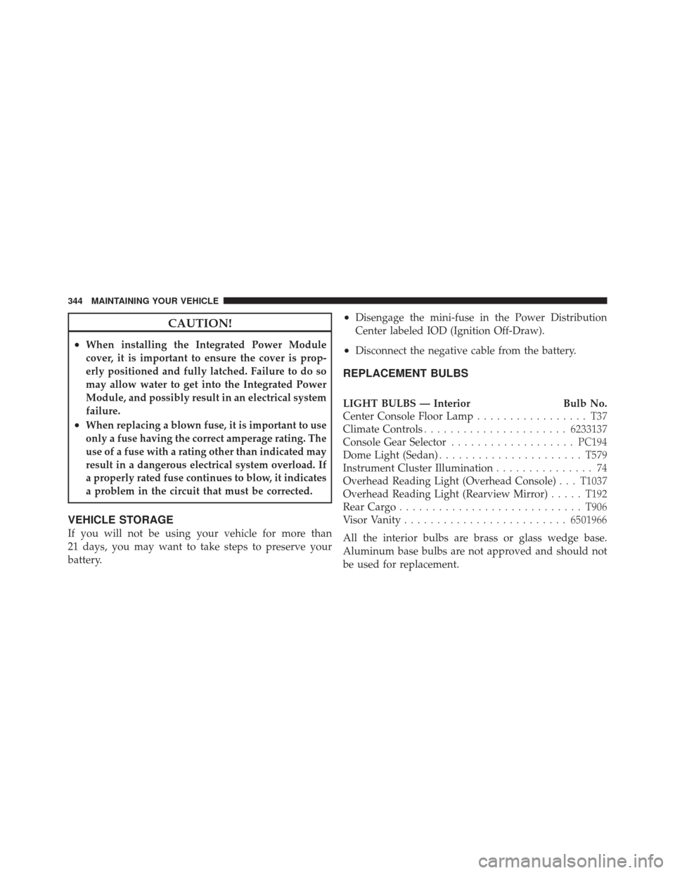
CAUTION!
•When installing the Integrated Power Module
cover, it is important to ensure the cover is prop-
erly positioned and fully latched. Failure to do so
may allow water to get into the Integrated Power
Module, and possibly result in an electrical system
failure.
•When replacing a blown fuse, it is important to use
only a fuse having the correct amperage rating. The
use of a fuse with a rating other than indicated may
result in a dangerous electrical system overload. If
a properly rated fuse continues to blow, it indicates
a problem in the circuit that must be corrected.
VEHICLE STORAGE
If you will not be using your vehicle for more than
21 days, you may want to take steps to preserve your
battery.
•Disengage the mini-fuse in the Power Distribution
Center labeled IOD (Ignition Off-Draw).
•Disconnect the negative cable from the battery.
REPLACEMENT BULBS
LIGHT BULBS — InteriorBulb No.
Center Console Floor Lamp ................. T37
Climate Controls ...................... 6233137
Console Gear Selector ................... PC194
Dome Light (Sedan) ...................... T579
Instrument Cluster Illumination ............... 74
Overhead Reading Light (Overhead Console) . . . T1037
Overhead Reading Light (Rearview Mirror) .....T192
Rear Cargo ............................ T906
Visor Vanity ......................... 6501966
All the interior bulbs are brass or glass wedge base.
Aluminum base bulbs are not approved and should not
be used for replacement.
344 MAINTAINING YOUR VEHICLE
Page 397 of 410

Cooling System....................... 323
Power Steering ........................ 241
Fluids ................................ 350
Fluids, Lubricants and Genuine Parts .......... 350
Fog Light Service ........................ 347
Fog Lights .......................... 128,172
Folding Front Passenger Seat ................ 113
Folding Rear Seat ........................ 116
Folding Rear Seat (Sedan) .................. 116
Freeing A Stuck Vehicle ................... 302
Fuel .............................. 270,350
Adding ............................. 274
Additives ............................ 272
Capacity ............................ 349
Clean Air ............................ 270
Ethanol ............................. 270
Filler Cap (Gas Cap) ................. 164,274
Filler Door (Gas Cap) ................... 164
Gasoline ............................ 270 Gauge
.............................. 164
Light ............................... 172
Materials Added ....................... 272
Methanol ............................ 270
Octane Rating ........................ 270
Requirements ......................... 270
Tank Capacity ........................ 349
Fuel System Caution ..................... 275
Fueling ............................... 274
Fuses ................................ 340
Garage Door Opener (HomeLink�) ........... 136
Gas Cap (Fuel Filler Cap) ............274,276,309
Gasoline, Clean Air ...................... 270
Gasoline (Fuel) ....................... 270,349
Gasoline, Reformulated ................... 270
Gauges Coolant Temperature ................... 164
Fuel ............................... 164
10
INDEX 395
Page 398 of 410

Odometer........................... 167
Tachometer .......................... 165
General Information ...............18,25,110,269
General Maintenance ..................... 312
Glass Cleaning .......................... 339
Gross Axle Weight Rating .................. 279
Gross Vehicle Weight Rating .............277,278
Hands-Free Phone (uconnect�) ............... 82
Hazard Driving Through Flowing, Rising,
or Shallow Standing Water ............... 237
Hazard Warning Flasher ................... 292
Head Restraints ......................... 114
Headlights Bulb Replacement ...................... 345
Cleaning ............................ 338
High Beam .......................... 129
High Beam/Low Beam Select Switch ........ 129Passing
............................. 130
Heated Seats ........................... 114
Hitches Trailer Towing ........................ 281
HomeLink� (Garage Door Opener) Transmitter . . . 136
Hood Release .......................... 123
Ignition ............................... 12
Key ................................ 12
Ignition Key Removal ..................... 12
Immobilizer (Sentry Key) .................15,19
Infant Restraint .......................... 62
Information Center, Vehicle ................. 178
Inside Rearview Mirror .................... 79
Instrument Cluster .................... 161,164
Instrument Panel and Controls .............. 160
Instrument Panel Cover ................337,339
Instrument Panel Lens Cleaning ............. 339
Integrated Power Module (Fuses) ............ 340
396 INDEX
Page 409 of 410

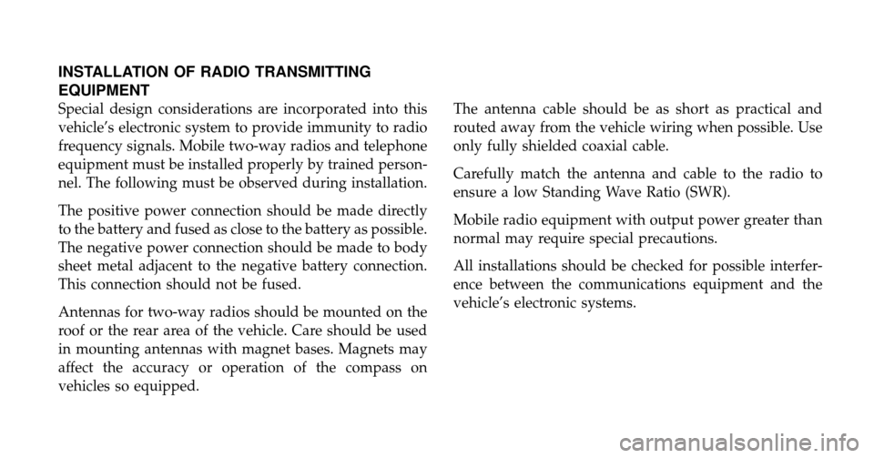
INSTALLATION OF RADIO TRANSMITTING
EQUIPMENT
Special design considerations are incorporated into this
vehicle’s electronic system to provide immunity to radio
frequency signals. Mobile two-way radios and telephone
equipment must be installed properly by trained person-
nel. The following must be observed during installation.
The positive power connection should be made directly
to the battery and fused as close to the battery as possible.
The negative power connection should be made to body
sheet metal adjacent to the negative battery connection.
This connection should not be fused.
Antennas for two-way radios should be mounted on the
roof or the rear area of the vehicle. Care should be used
in mounting antennas with magnet bases. Magnets may
affect the accuracy or operation of the compass on
vehicles so equipped.The antenna cable should be as short as practical and
routed away from the vehicle wiring when possible. Use
only fully shielded coaxial cable.
Carefully match the antenna and cable to the radio to
ensure a low Standing Wave Ratio (SWR).
Mobile radio equipment with output power greater than
normal may require special precautions.
All installations should be checked for possible interfer-
ence between the communications equipment and the
vehicle’s electronic systems.